Tension Crack
A Tension Crack can be included in the SWedge analysis, by selecting the Tension Crack check box in the Input Data dialog, and defining the Tension Crack orientation and location, as described below.
NOTE:
- A Tension Crack is optional in the SWedge analysis. By default, SWedge does NOT consider a Tension Crack in the analysis.
- By definition, a Tension Crack in SWedge has ZERO shear strength. It does NOT contribute to the forces resisting wedge movement. It simply truncates the size of the wedge.
- However, if Water Pressure is included in the analysis, the resultant force will be applied to the Tension Crack plane, if applicable.

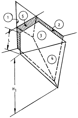
Definition of Tension Crack for SWedge analysis (plane # 5)
Tension Crack Orientation
The Tension Crack orientation is defined by entering the Dip and Dip Direction of the Tension Crack plane in the Input Data dialog.
NOTES:
- The Tension Crack does NOT have to be vertical. SWedge allows you to enter any orientation for the Tension Crack plane.
- However, if a Tension Crack is defined, SWedge examines how the Tension Crack intersects the other planes, and only accepts those cases where the Tension Crack truncates the wedge in the manner shown in the figure above.
- If the Tension Crack plane does not form an acceptable wedge with the other planes, SWedge will report "No Wedge Formed".
- A Tension Crack is not "interchangeable" with a joint plane in the SWedge analysis (i.e. it will not be considered as a joint plane, regardless of the Tension Crack orientation).
- In a Probabilistic Analysis, you can define statistical variability of the Tension Crack orientation.
Tension Crack Location
In the Input Data dialog, there are THREE possible methods of defining the Tension Crack Location:
- Minimum FS Location
- Specify Location
- Use Bench Width to Maximize
These options are described below.
MINIMUM FS LOCATION
If this option is selected, then SWedge will automatically determine the location of the Tension Crack which results in the MINIMUM Factor of Safety for the wedge. Note that this uses an iterative approach whereby SWedge test several Tension Crack locations to find the location with the minimum Factor of Safety.
SPECIFY LOCATION
If this option is selected, then the location of the Tension Crack can be user-defined by entering a Trace Length with respect to Joint 1. The Trace Length is the distance of the Tension Crack from the crest, measured along the trace of Joint 1 on the Upper Slope Face. See the above figure. Length L is the trace length used to specify the Tension Crack location.
USE BENCH WIDTH TO MAXIMIZE
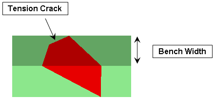
If this option is selected, then SWedge will automatically locate the Tension Crack to create the maximum possible wedge size for the specified Bench Width. This is illustrated in the following figure. Note that this uses an iterative approach whereby SWedge test several Tension Crack locations to find the location with the maximum wedge volume.

Tension Crack location determined by Bench Width
Tension Crack and Basal Joint Wedges
If you are using the Basal Joint option, a Tension Crack can be included in the same manner as described above for tetrahedral wedges. However note the following differences:
- The Tension Crack Location can only be defined using the Specify Location option. The Minimum FS Location and the Use Bench Width to Maximize options will not be available.
- The location of a tension crack for a basal joint wedge is defined differently than for a tetrahedral wedge. See the Basal Joint Wedge document for details.
Minimum Tension Crack Area
You can optionally ignore the existence of a Tension Crack if the computed Tension Crack area is smaller than the specified threshold by selecting the Minimum Tension Crack Area checkbox. When Minimum Tension Crack Area is selected:
- If the Tension Crack area is larger than or equal to the specified Minimum Tension Crack Area, then the Factor of Safety computation will use the Tension Crack
- If the Tension Crack area is smaller than the specified Minimum Tension Crack Area, then the Factor of Safety computation will ignore the Tension Crack and compute as if Tension Crack is not selected.
This allows us to ignore any negligible Tension Cracks that may be formed.