Deep Excavation
1.0 Introduction
This tutorial introduces how to model deep excavation with support system in RS3.
All tutorial files installed with RS3 can be accessed by selecting File > Recent > Tutorials folder from the RS3 main menu. The initial file of the tutorial can be found in Deep Excavation - starting file.rs3v3 and the finished tutorial can be found in the Deep Excavation.rs3v3 file.
2.0 Starting the Model
- Select: File > Recent > Tutorials Folder
- Open the Deep Excavation - starting file.rs3v3
- Open Project Settings dialog by selecting Analysis > Project Settings

- Set Units to Metric, stress as kPa
- Select the Stages tab. Check the stage names:
- Initial
- Install sheet pile
- Excavation 1
- Bracing Installation
- Excavation 2
- Tieback Installation
- Excavation 3
3.0 Defining the Materials
Ensure the current workflow tab is set to Geology 
- Select: Materials > Define Materials
In the Stiffness tab, assign the parameters for Loose Sand, Stiff Clay, and Dense Sand as the following table:
Property Loose Sand
Stiff Clay
Dense Sand
Use Unloading Condition Enabled
Enabled
Enabled
Poisson’s Ratio (Loading) 0.3
0.35
0.25
Young’s Modulus (Loading) (kPa) 15000
40000
80000
Poisson’s Ratio (Unloading) 0.3
0.3
0.3
Young’s Modulus (Unloading) (kPa) 45000
120000
400000
In the Strength tab, set the Failure criterion to Mohr-Coulomb and Material Type to Plastic for Loose Sand, Stiff Clay, and Dense Sand.
Define the parameters as shown in the following table:Property Loose Sand
Stiff Clay
Dense Sand
Peak Cohesion (kPa) 0
100
0
Peak Friction Angle (°) 30
0
40
Peak Tensile Strength (kPa) 0
0
0
Residual Cohesion (kPa) 0
100
0
Residual Friction Angle (°) 30
0
40
Residual Tensile Strength (kPa) 0
0
0
- Select OK to save and close the Material Properties dialog
4.0 Model Setup
4.1 BOREHOLE DATA
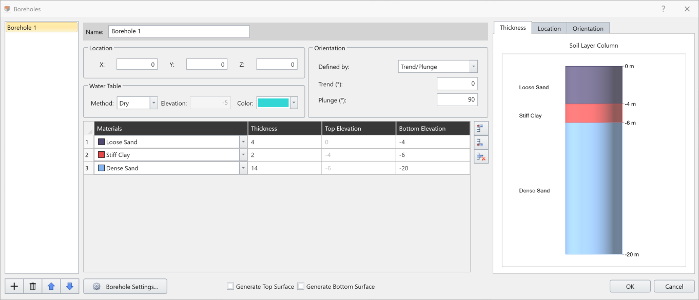
The soil horizons of this model are defined using the borehole data. Follow the procedure below to review the borehole profile.
- Select: Materials > Borehole Manager
- Click OK
4.2 DEFINING SOIL LAYERS IN THE MODEL
- Select the External Entity from the Visibility Tree
- Select: Geometry > Set as External
Select: Geometry > 3D Boolean > Divide All Geometry
- Keep the default settings and click OK
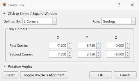
- Select: Geometry > 3D Primitive Geometry > Box
- Write the following data:
Click OK
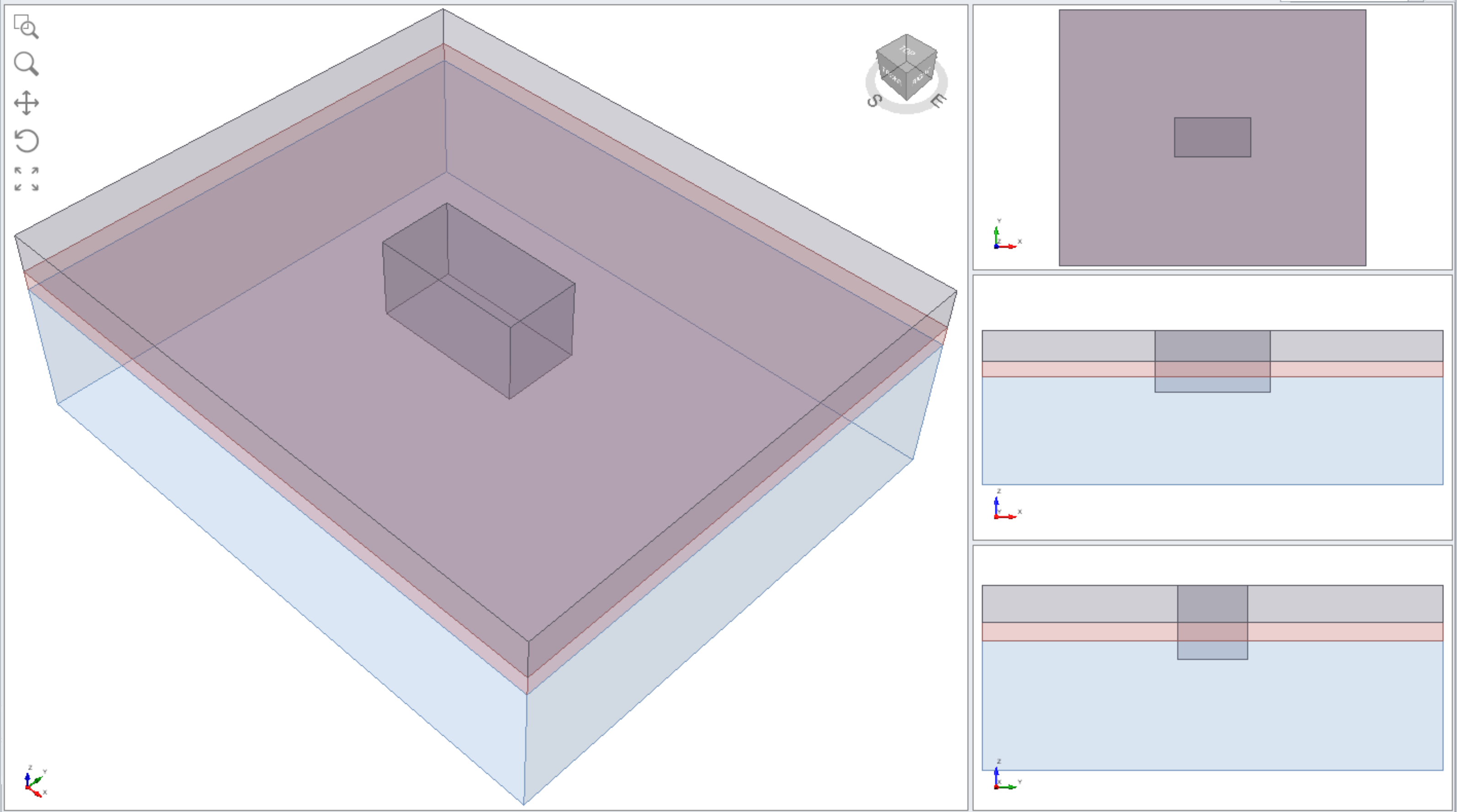
4.3 DEFINING THE EXCAVATION ZONE
Select the Box Entity from the Visibility Tree
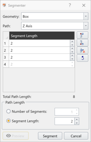
From the Properties Pane, change the Applied Property to DeriveNon-external geometry entities can have its Applied Property set to Derived. Those entities will adopt the applied property setting of the parent external entity upon Divide All. This is particularly useful when the purpose of Divide All is to create boundaries while preserving the established material properties assignment to the existing external volumes.- Select the Box Entity and select: Geometry > 3D Boolean > Segmenter
- Change Path to Z Axis
- Keep Path Length to Number of Segments: 1
Click on add segment above button and input 6
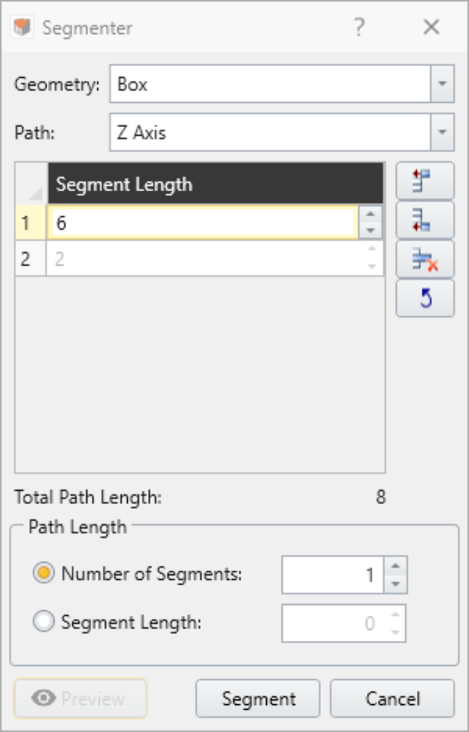
- Click Segment
- Select: Geometry > 3D Boolean > Divide All Geometry
- Click Ok
4.4 EXCAVATION SEQUENCE
Set the current workflow tab to Excavations 
- Select Excavation 1 stage
Select top layer Box Entity
From the Properties Pane, change the Applied Property to No Material - Select Excavation 2 stage
Select second layer from the top Box Entity
From the Properties Pane, change the Applied Property to No Material - Select Excavation 3 stage
Select the third layer from the top Box Entity From the Properties Pane, change the Applied Property to No Material
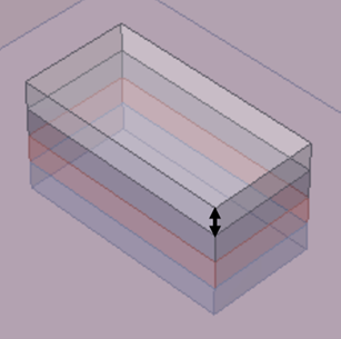
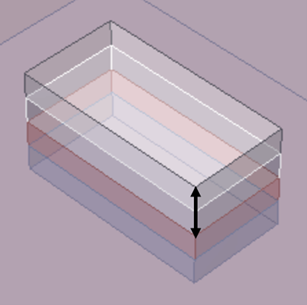
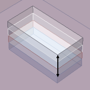
Excavation 1
Excavation 2
Excavation 3
4.5 PREDEFINING LOCATION OF BRACING AND STRUTS
- Select: Geometry > Polyline Tools > Draw Polyline
- Select: Plane Orientation = XY
- Then enter the following U,V Coordinates (press Enter between each pair and right-click > Finish Current Polyline between each line):
1st Line: (-4.25, -3.75) and (-7.5, -0.5)
2nd Line: (-7.5, 0.5) and (-4.25, 3.75)
3rd Line: (0, -3.75) and (0, 3.75)
4th Line: (4.25, -3.75) and (7.5, -0.5)
5th Line: (7.5, 0.5) and (4.25, 3.75)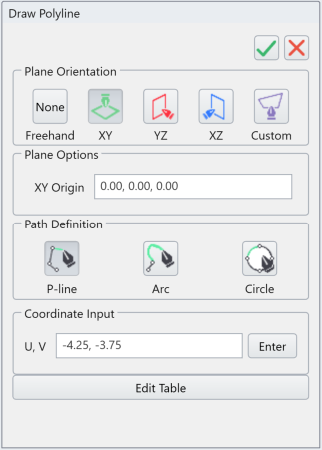
- Select the green checkmark

- Select all the Polyline entities in the visibility pane
- Select: Geometry > Extrude/Sweep/Loft Tools > Extrude
- Enter Direction (x, y, z) = (0, 0, -1), Depth = 2 and click OK
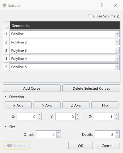
- Select all the Extruded Polyline Entities and set Role to Geology from the Properties Pane
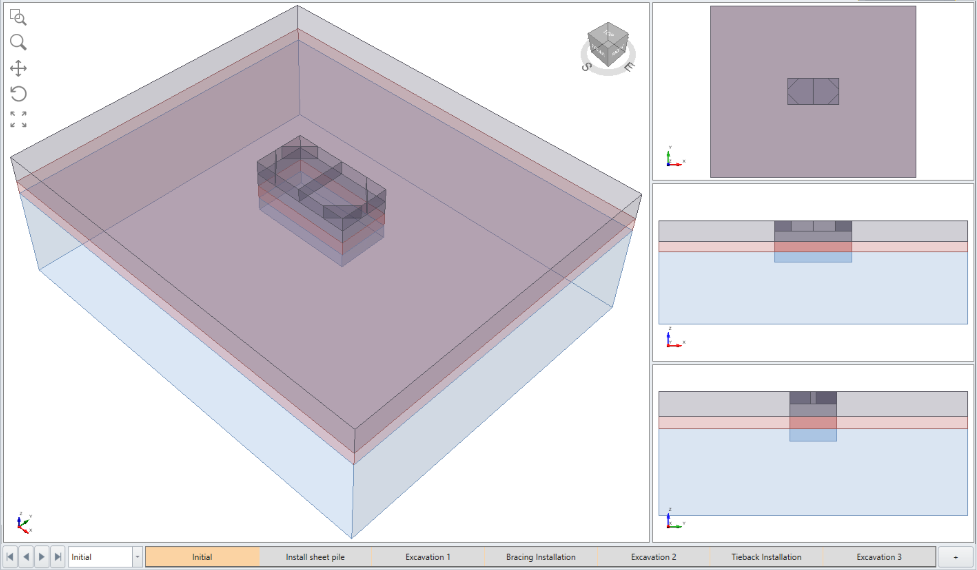
- Select: Geometry > 3D Boolean > Divide All Geometry
- Click OK
- This completes the excavation volume creation and setup for the support installation, continued next section
5.0 Supports
Set the current workflow tab to Support 
5.1 WALL
For the sheet pile wall, we are using the equivalent thickness parameter for liner size AZ 20-700.
5.1.1 Define Liners
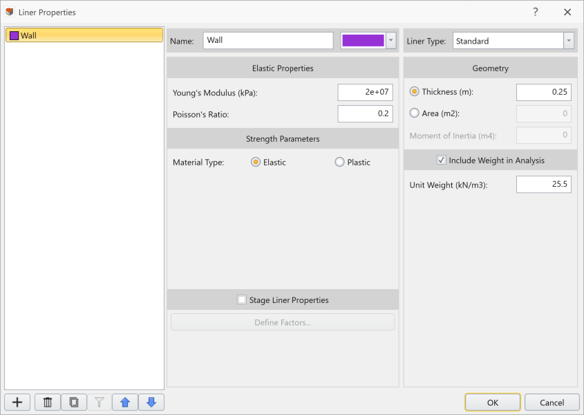
- Select: Support > Liners > Define Liner Properties
Input the following parameters:- Young's Modulus (kPa): 2e+07 and Poisson's Ratio of 0.2
- Thickness: 0.25
- Enable the Include Weight in Analysis Option and input Unit Weight (kN/m3): 25.5
- Click OK
- Select: Support > Liners > Define Lining Composition
- Change Name to SheetPile Wall
- Add interfaces above and below the lining layer by selecting the Up
 and Down
  icons under the Edit column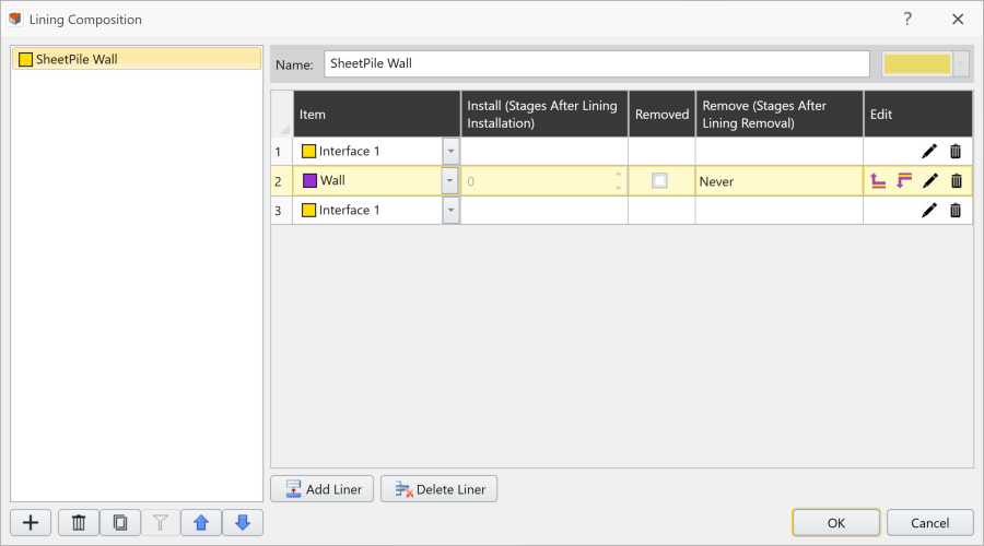
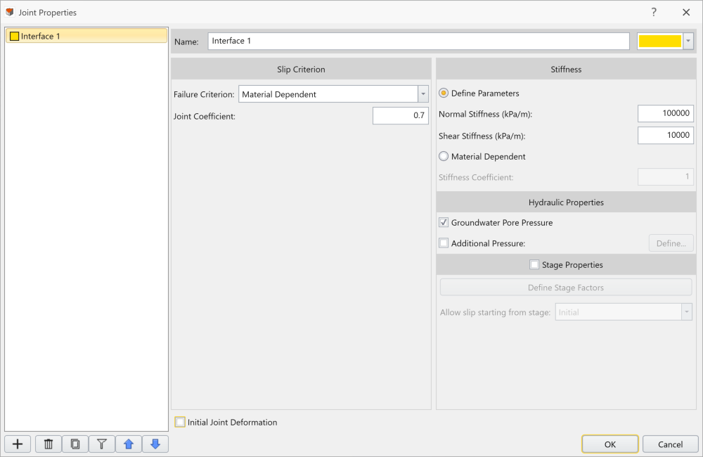
- To modify/define the interface property, select the pencil icon
 of Interface 1
Make sure to uncheck Initial Joint Deformation and input the following parameters:- Failure Criteria: Material Dependent
- Joint Coefficient: 0.7
- Click OK to close the Joint Properties dialog
- Click OK to close the Lining Composition dialog
5.1.2 Install Wall
- Select Install sheet pile stage
- Hide all entities from the Visibility Tree but the excavation volumes
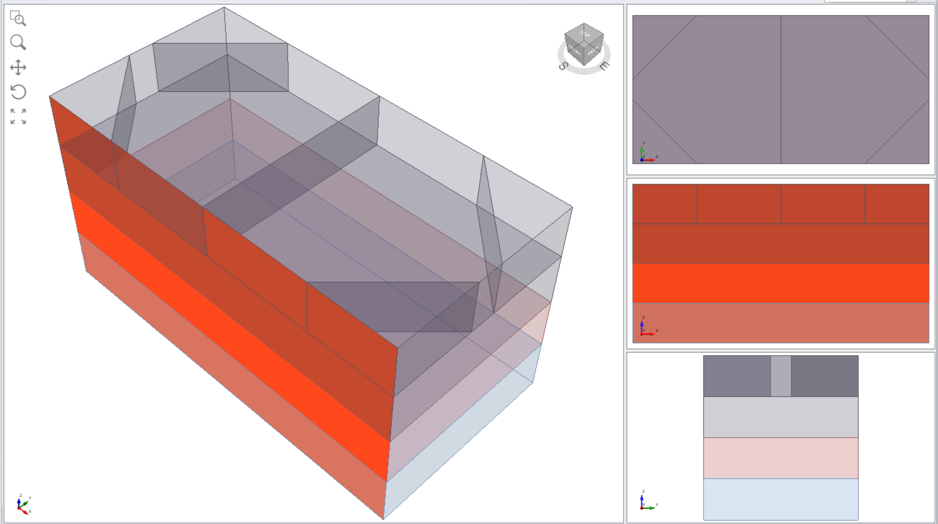
- Select Face Selection

Select the front-facing surfaces (from the front view)
- Select: Support > Liners > Add Lining
Make sure the parameters are as follows: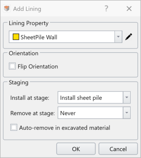
- Click OK
Repeat steps 5 and 6 for the right, back, and left faces
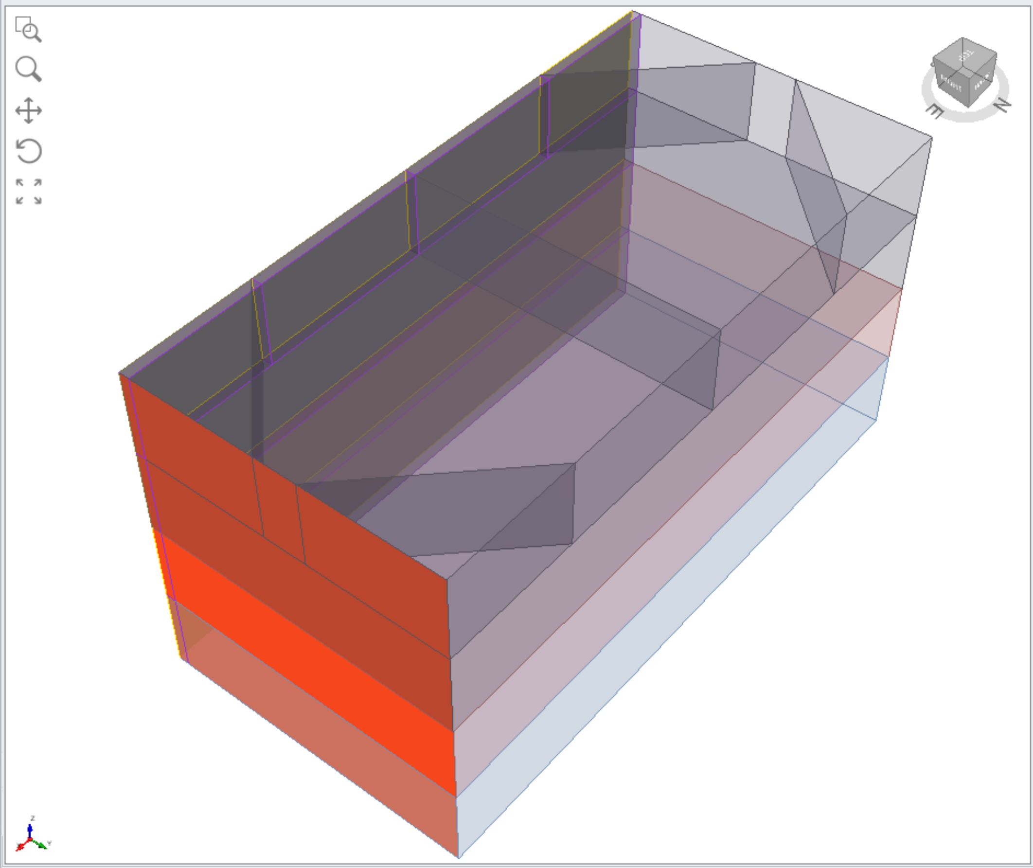
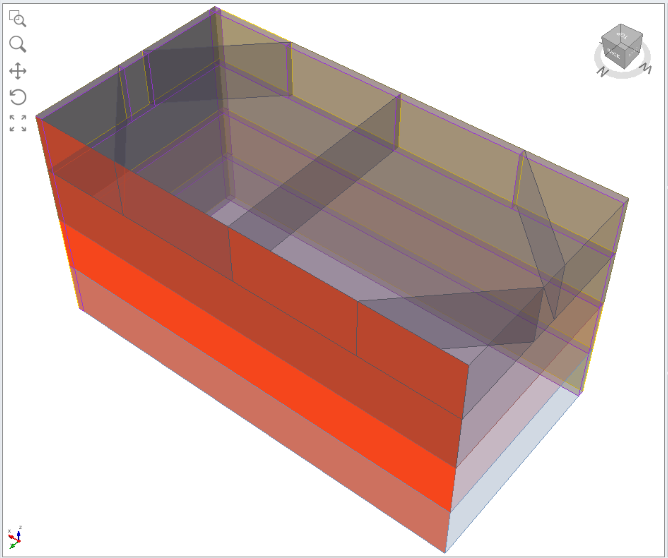
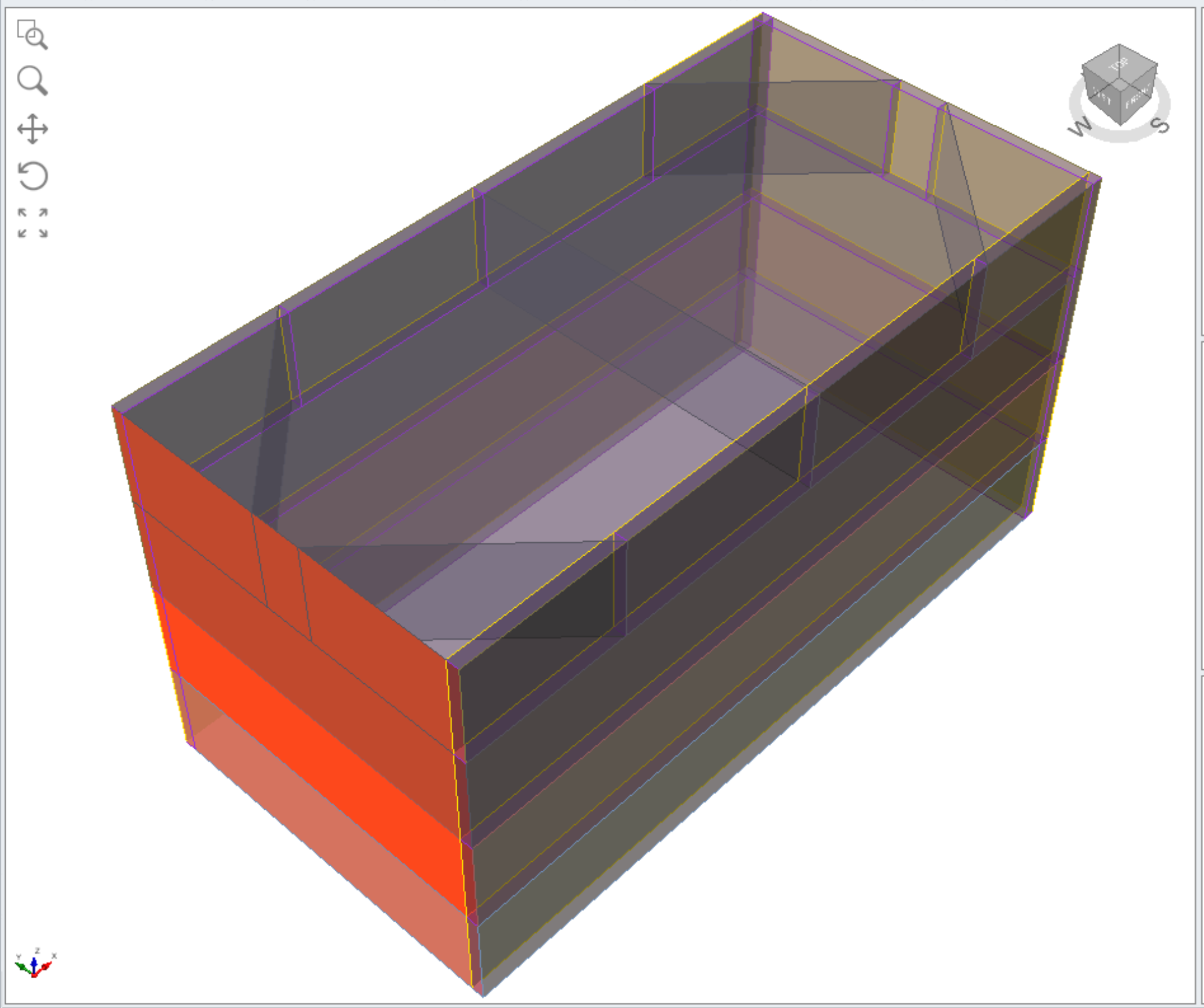
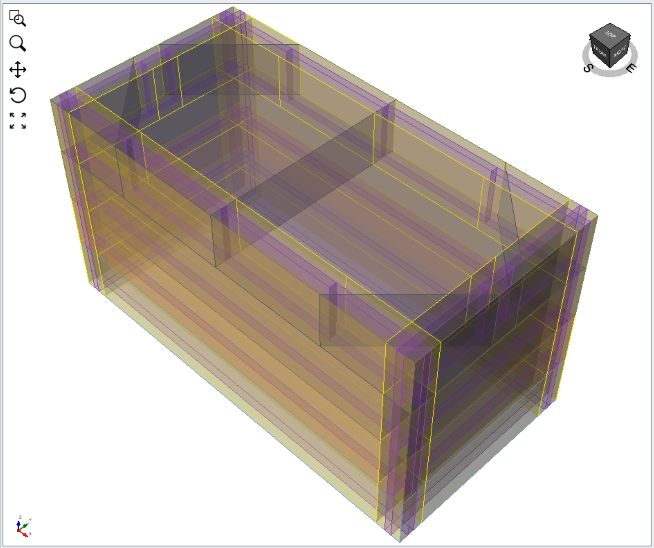
- To visualize the compositions of composite liner layers more apparently, follow the procedure below:
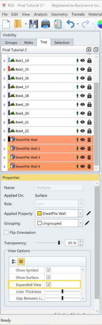
- Select all four SheetPile Wall entities
- Select Expanded View from the Properties Pane
- The thickness/interface-liner gap can be controlled with the sliders for Liner Thickness and Gap between Liners
5.2 BRACING
5.2.1 Define Beams
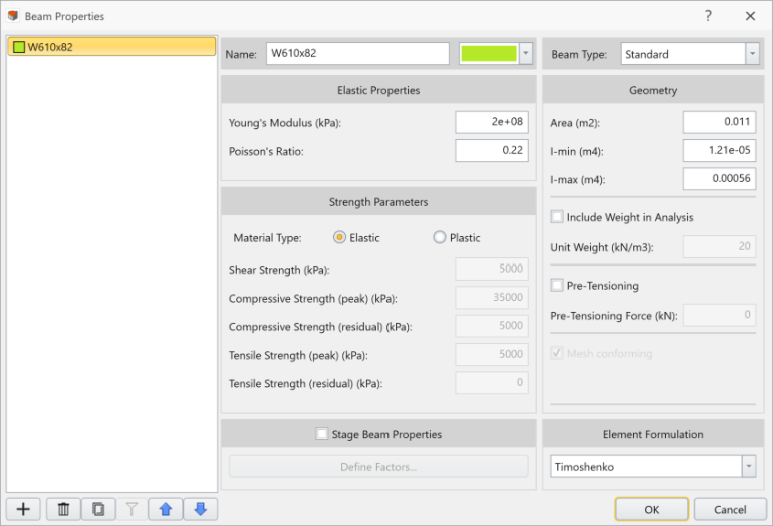
- Select: Support > Beams > Define Beams
Input the following parameters:- Name: W610x82
- Young’s Modulus (kPa): 2e+08
- Poisson’s Ratio: 0.22
- Area (m2): 0.011
- I-min (m4): 1.21e-05
- I-max (m4): 0.00056
- Click the Add new property button
 to add a new property
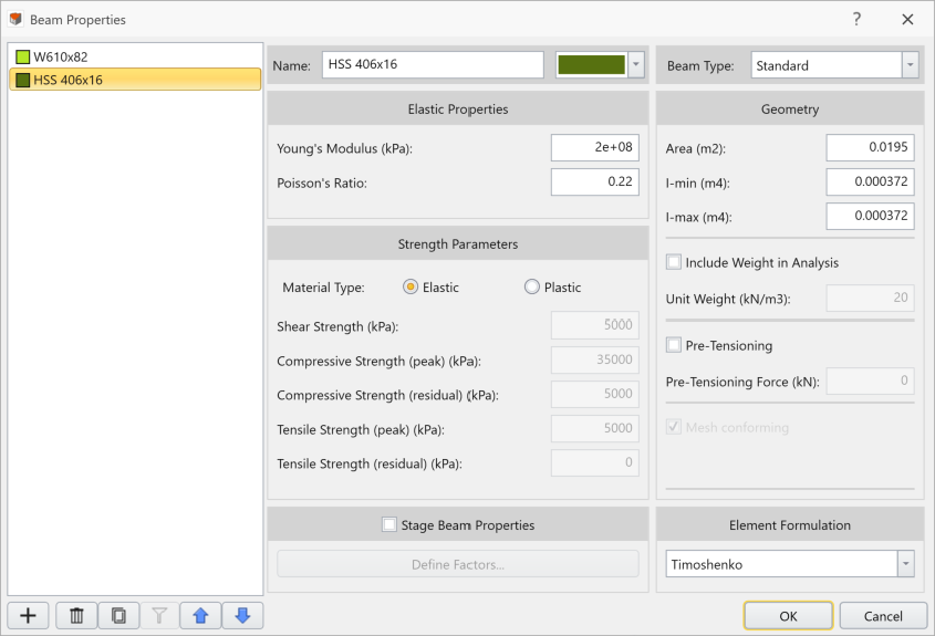
Input the following parameters:- Name: HSS 406x16
- Young’s Modulus (kPa): 2e+08
- Poisson’s Ratio: 0.22
- Area (m2): 0.0195
- I-min (m4): 0.000372
- I-max (m4): 0.000372
- Click OK
5.2.2 Add Beams
- Select Bracing Installation stage
- Hide all entities from the visibility pane, but the excavation volumes
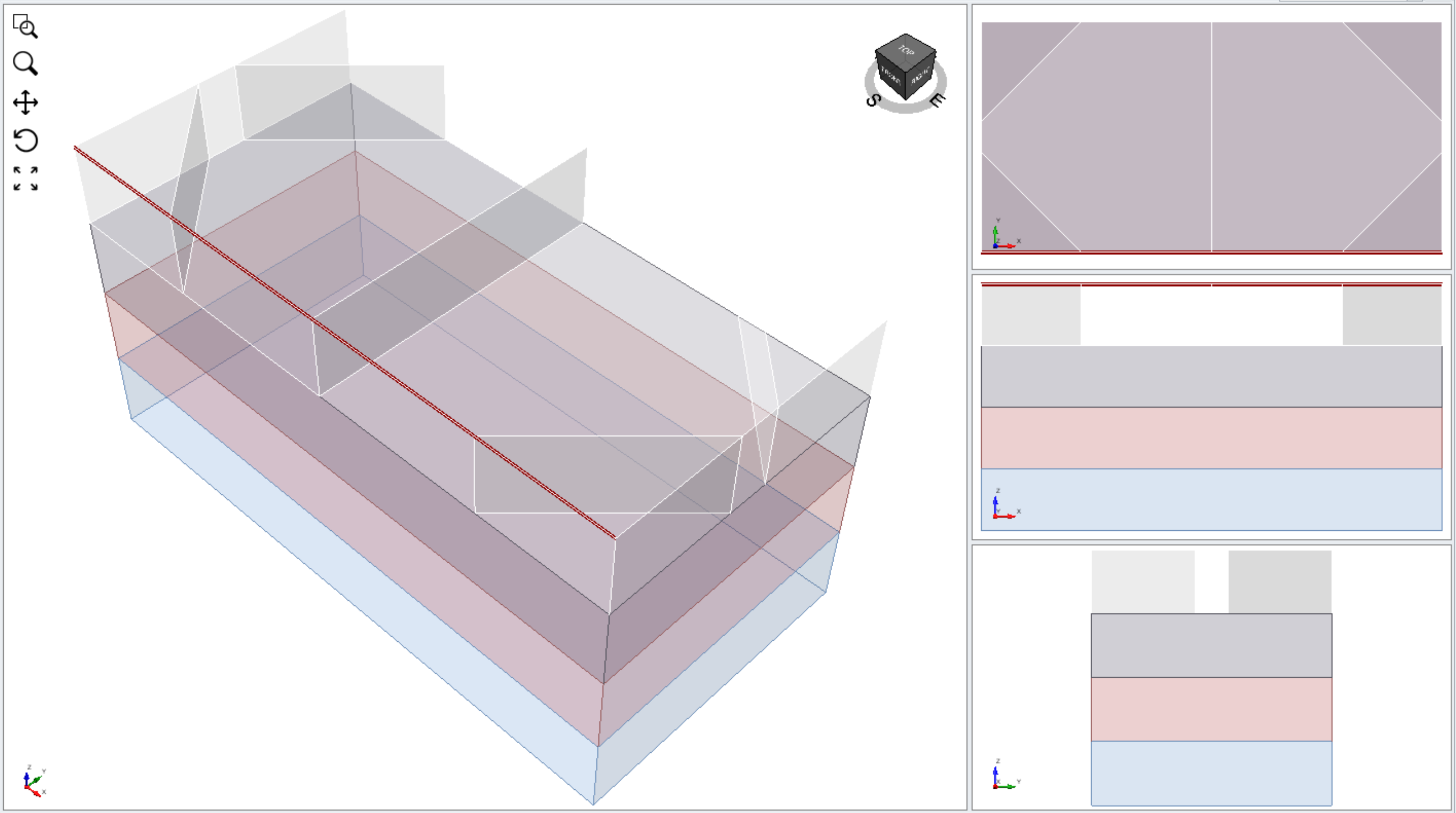
- Select Edges Selection

Select the top horizontal edges on the front side:
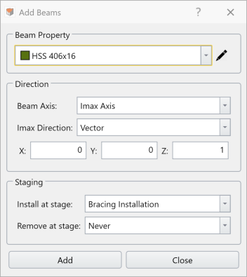
- Select: Support > Beams > Add Beams
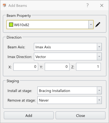
- Beam Property: W610x82
- Beam Axis: Imax Axis
- Imax Direction: Vector (0, 0, 1)
- Install at stage: Bracing Installation
- Click Add
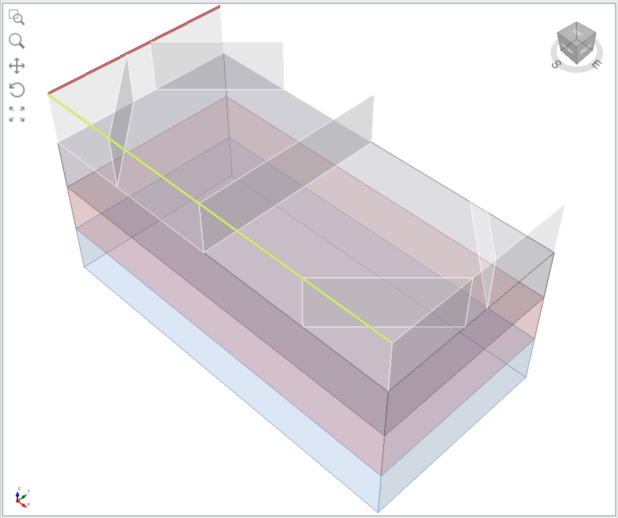
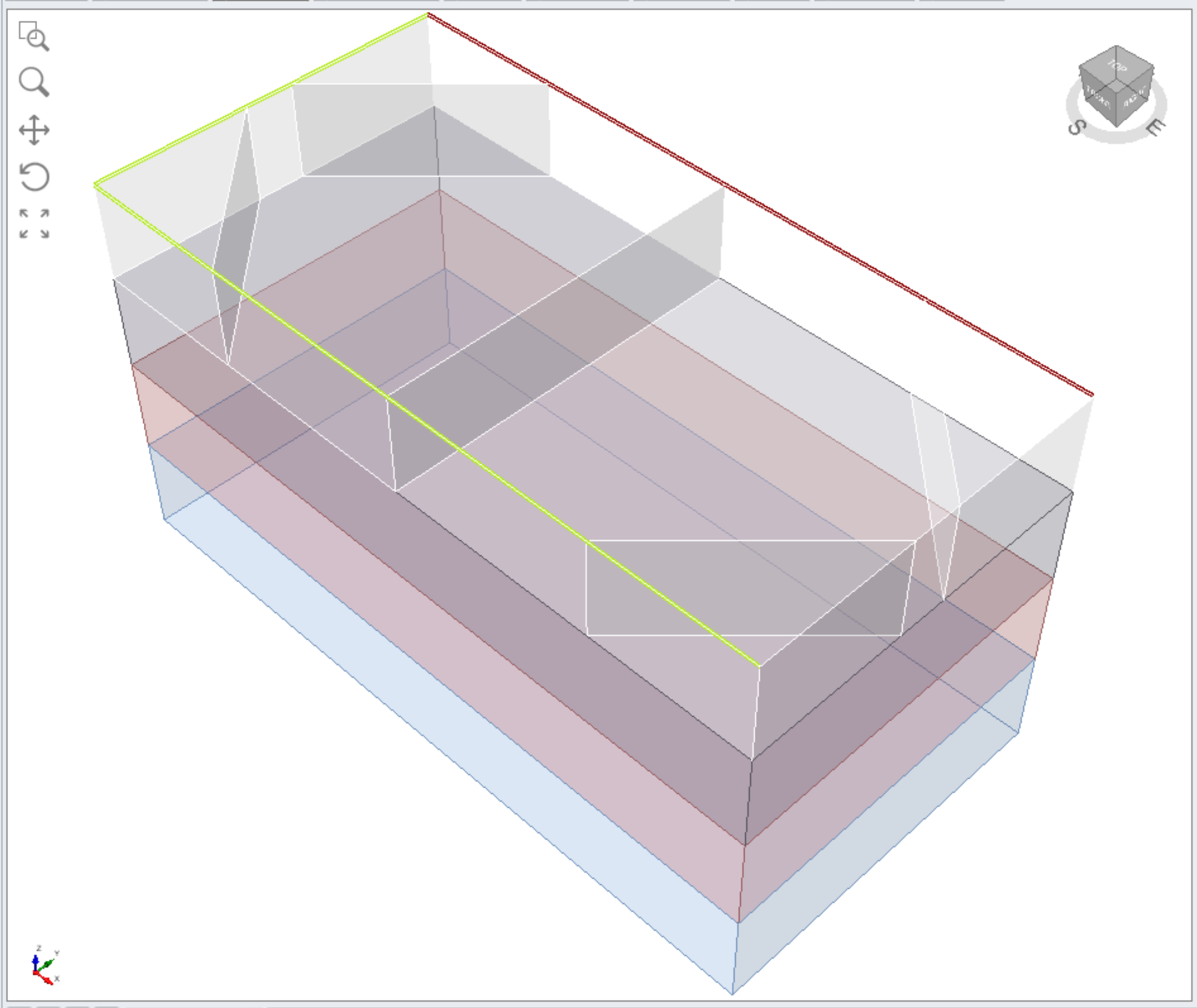
Repeat steps 5 and 6 for the rest of the outer edges as shown below
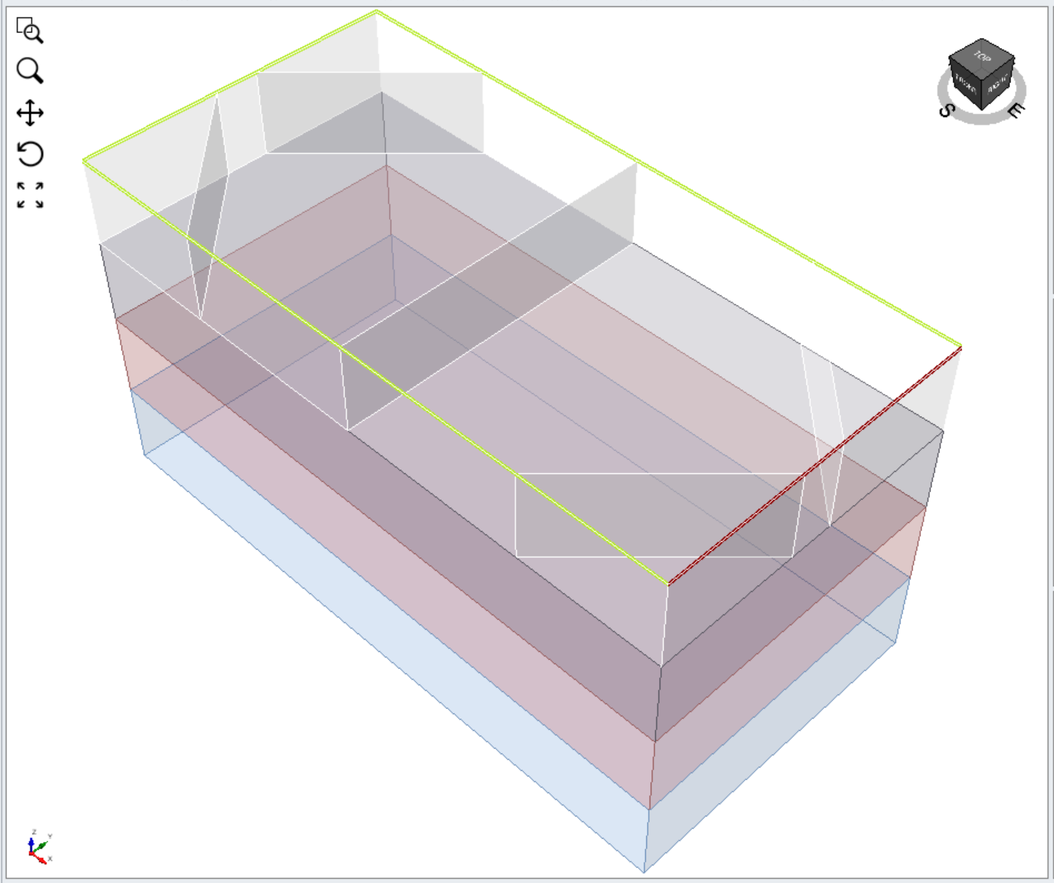
- Internal diagonal edges will be selected for HSS 406x16 beam installation
Select the following edge at the front-left:
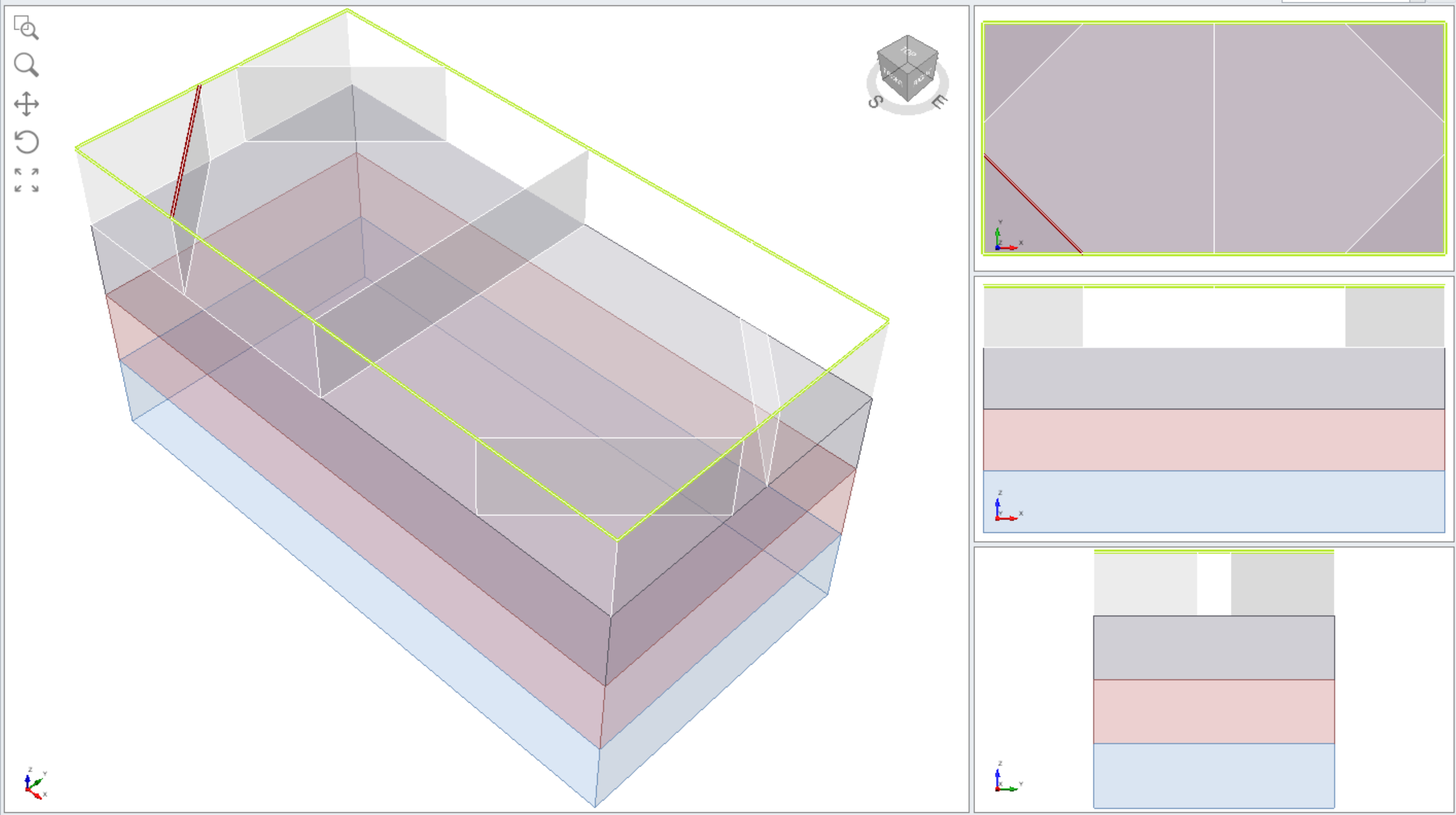
- Change the Beam Property to HSS 406x16
- Click Add
- Repeat steps 10 and 11 for the rest of the internal diagonal edges and the center edge
- Click Close to close the Add Beams dialog
- The clip below shows the edge selection procedures to add beams as described in this section:
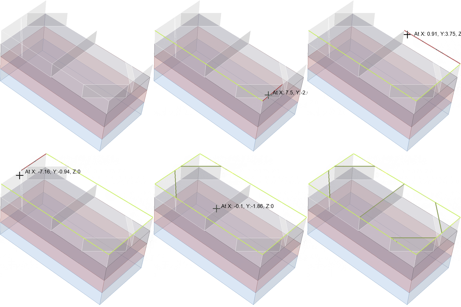
The table below shows the difference between the orientation of the beam depending on the beam axis:
| Beam Axis | Imin Axis | Imax Axis |
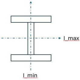 | 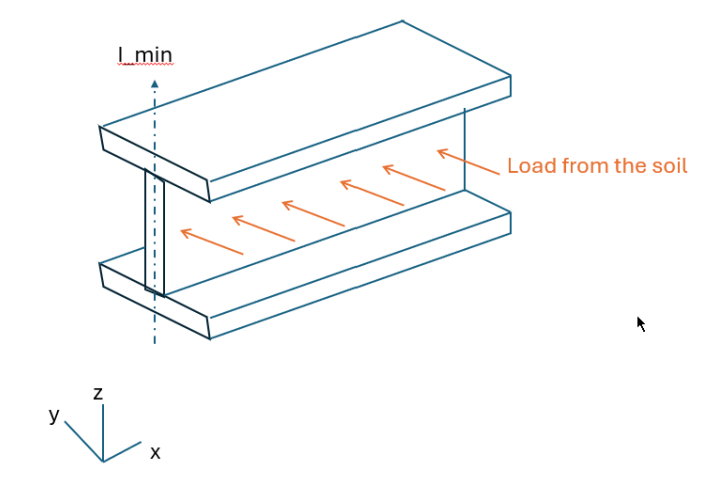 | 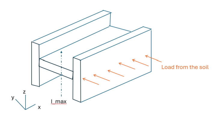 |
5.3 BOLTS
5.3.1 Define Bolts
- Select: Support > Bolts > Define Bolts
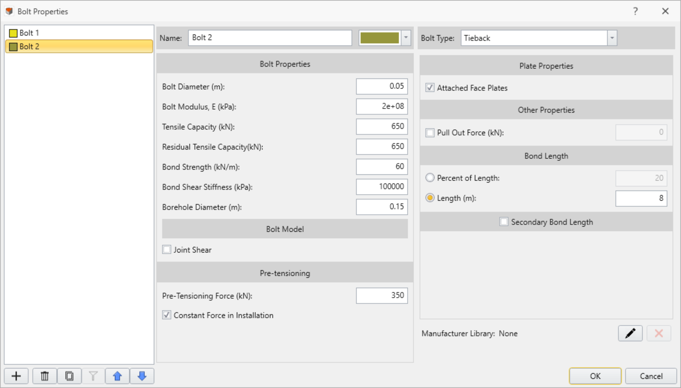
Define Bolt 1 and Bolt 2 properties as follows:
Property Bolt 1
Bolt 2
Bolt Type Tieback
Tieback
Bolt Diameter (m) 0.05
0.05
Tensile Capacity (kN) 650
650
Residual Tensile Capacity (kN) 650
650
Bond Strength (kN/m) 60
60
Borehole Diameter (m) 0.15
0.15
Joint Shear Unchecked
Unchecked
Pre-Tensioning Force (kN) 100
350
Length (m) 6
8
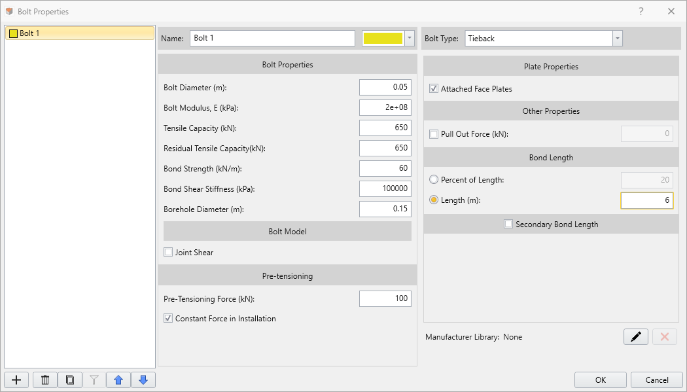
- Click OK
5.3.2 Add Bolts
- Select Tieback Installation stage
- Hide all entities from the visibility pane except the boxes
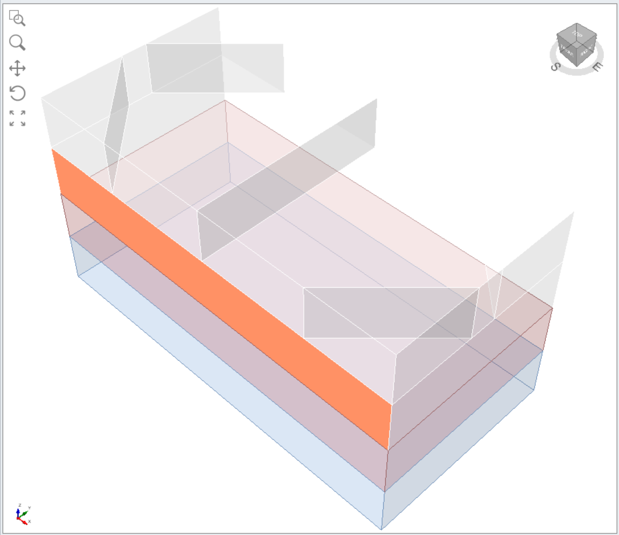
- Select Faces Selection
Select the following face:
- Select: Support > Bolts > Add Bolts to Surface
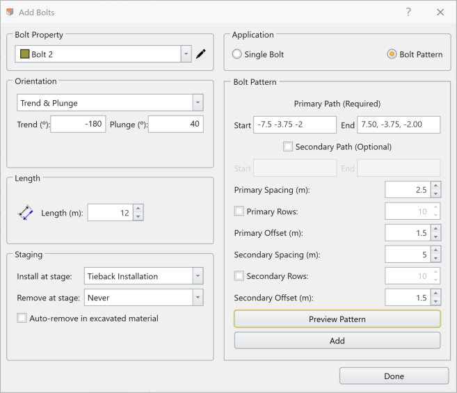
- Input the following parameters:
- Bolt Property: Bolt 2
- Orientation: Trend and Plunge
- Trend (°) / Plunge (°): -180 /40
- Length (m): 12
- Install at stage / Remove at stage: Tieback Installation / Never
- Application: Bolt Pattern
- Primary Path: Start: -7.5, -3.75, -2 and End: 7.5, -3.75, -2
- Primary Spacing (m): 2.5
- Primary Offset (m): 1.5
- Secondary Spacing (m): 5
- Secondary Offset (m): 1.5
- Click Add
- Click Done
Repeat these steps for the other three surfaces on the same level with following parameters:
Property Right side
Back side
Left side
Bolt Property Bolt 1
Bolt 1
Bolt 1
Length (m) 9
9
9
Trend (°) / Plunge (°) 090/40
000/40
-090/40
Install at stage / Remove at stage Tieback Installation / Never
Tieback Installation / Never
Tieback Installation / Never
Application Bolt Pattern
Bolt Pattern
Bolt Pattern
Primary Path Start 7.5 -3.75 -2
7.5 3.75 -2
-7.5 3.75 -2
Primary Path End 7.5 3.75 -2
-7.5 3.75 -2
-7.5 -3.75 -2
Primary Spacing (m) 2
2.5
2
Primary Offset (m) 0.75
1.5
0.75
Secondary Spacing (m) 5
5
5
Secondary Offset (m) 1.5
1.5
1.5
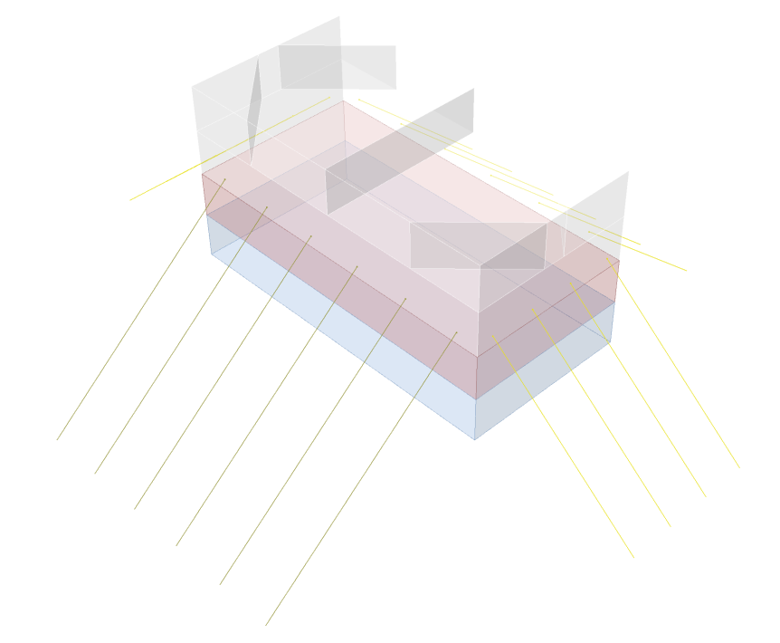
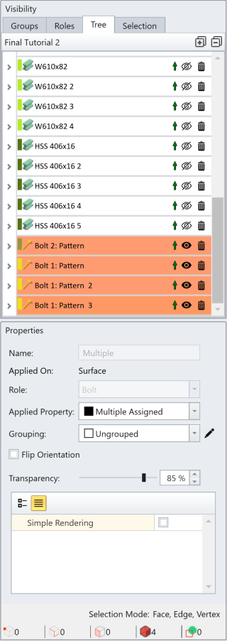
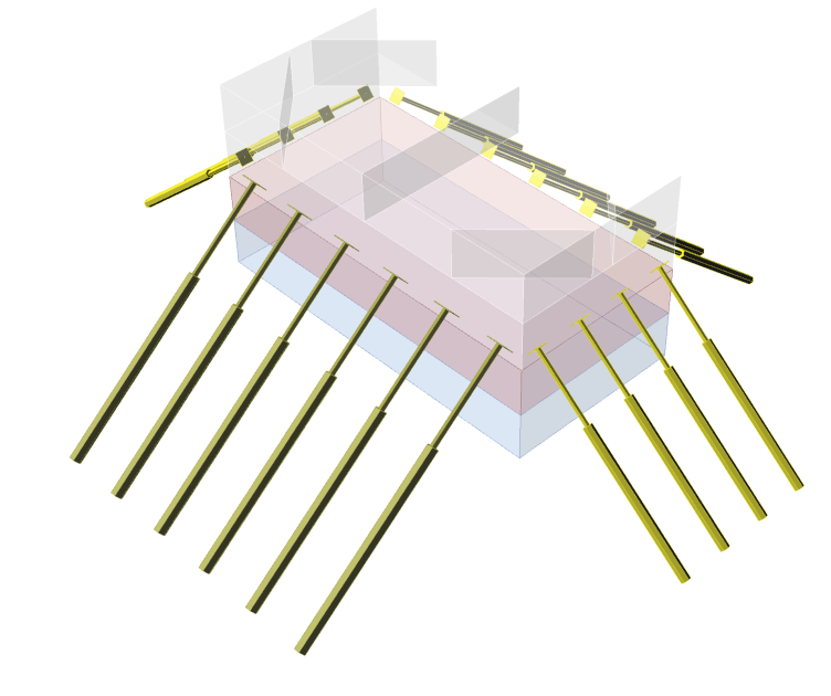
- Select all the bolt entities from the visibility tree > unselect Simple Rendering to show the bonded portion of bolts
6.0 Loading
Set the current workflow tab to Loads 
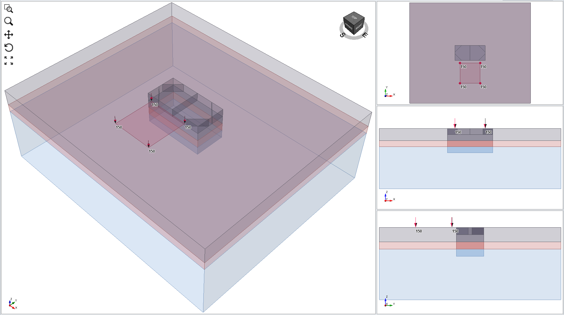
In this section, we will setup the initial stress condition subsurface and add a load to represent that of the existing building.
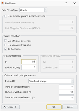
- Select: Loading > Field Stress
- Set K1= 0.5 and leave the rest of the parameters with default settings
- Click OK
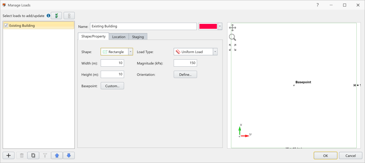
- Select: Loading > Define Projected Load
- Change Name to Existing Building
- Input the following parameters in the Shape/Property tab:
- Width (m): 10
- Height (m): 10
- Magnitude (kPa): 150
- In the Location tab, change the Location to (0, -10)
- Verify the Existing Building load item remains selected
Click OK
7.0 Restraints
Set the current workflow tab to Restraints 
- Select: Restraints > Reset All Displacements
- Select Reset Displacements after stages:
- Leave the displacement resetting stage as Initial
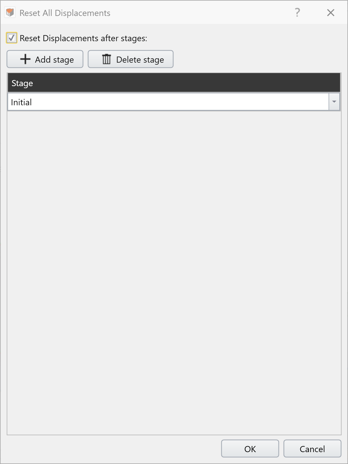
- Select OK
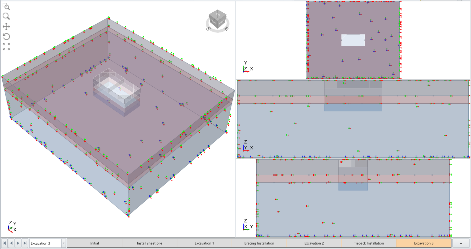
- Select: Restraints > Auto Rotation Restrain (Surface)
8.0 Mesh
Set the current workflow tab to Mesh 
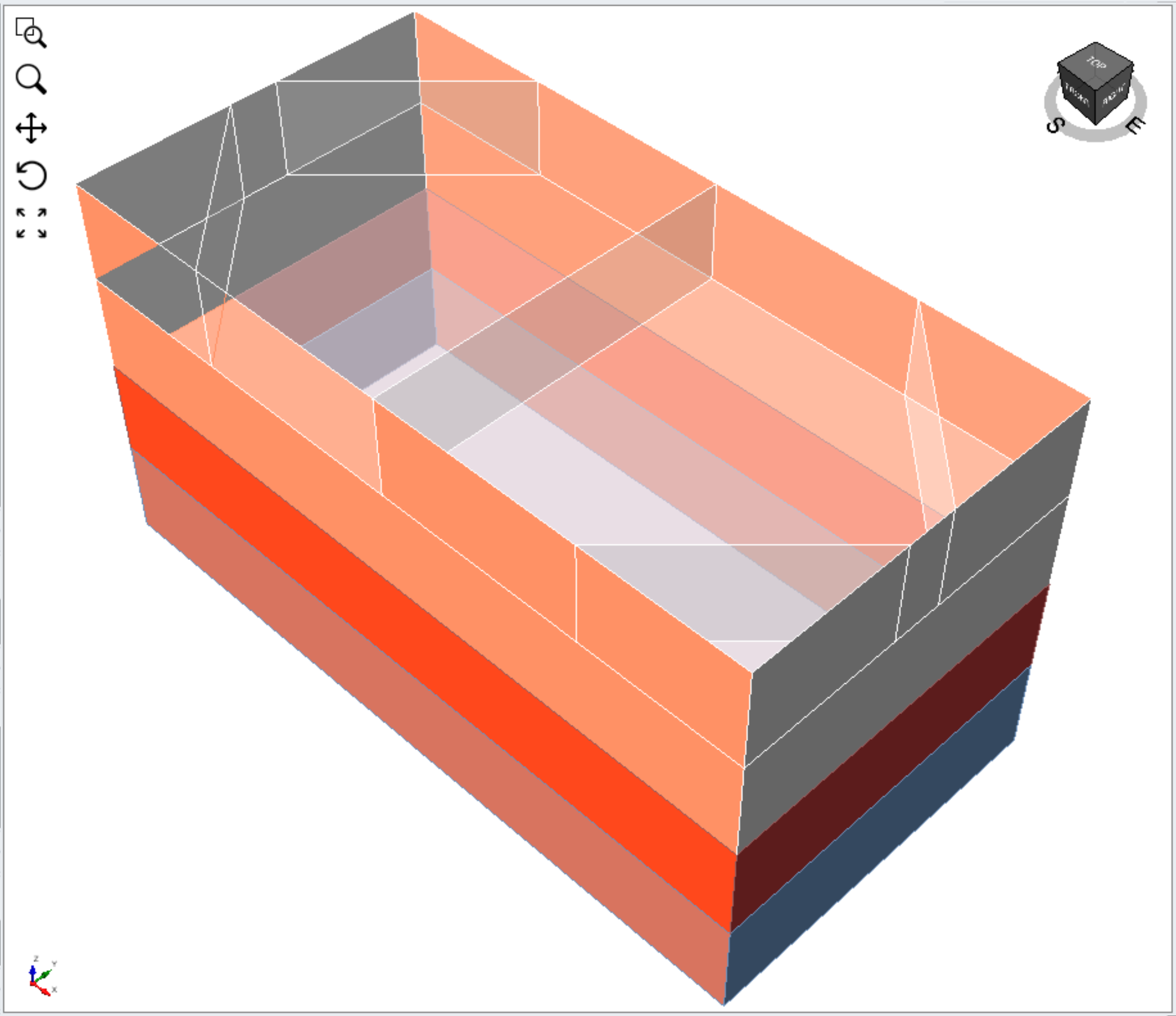
- Hide all entities except boxes
- Select Faces Selection
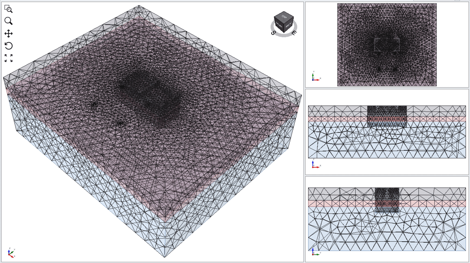
Select all faces on the sides of the excavation volumes,
- Select: Mesh > Define Refinement Regions
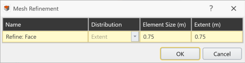
- Input the following parameters:
- Element Size (m): 0.75
- Extent (m): 0.75
- Click OK
- Select: Mesh > Mesh Settings
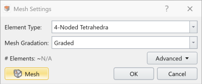
- Keep the default settings and select Mesh
Click OK
9.0 Compute
Set the current workflow tab to Compute 
- It is recommended to save the final model as a seperate file so that you can access the original file anytime: File > Save As
- Select: Compute > Compute

10.0 Results
Set the current workflow tab to Results 
10.1 EXCAVATION RESULTS
- Select Excavation 3 stage
- On the top right corner, set the Legend to Solids and Total Displacement
Select: Interpret > Show Data on Plane > XZ
Leave default parameters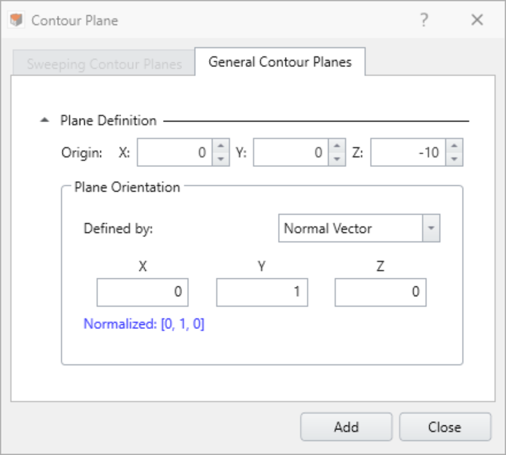
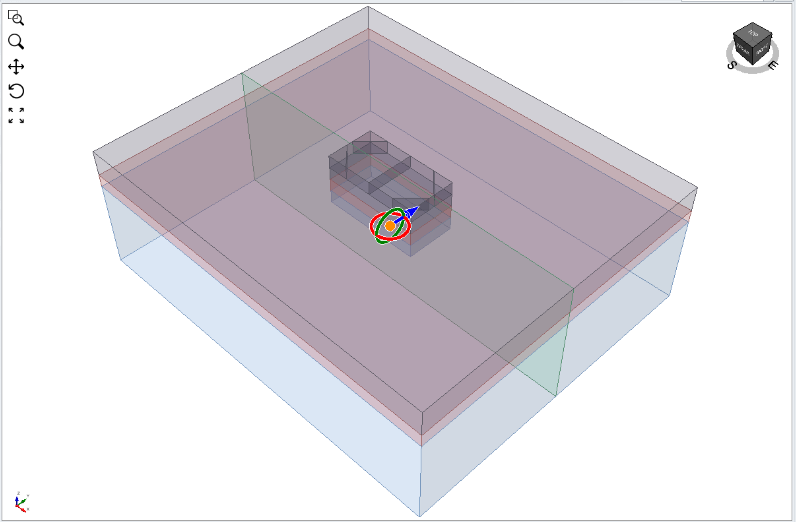
- Click Add
Adjust the plane orientation to (1, 0, 0)
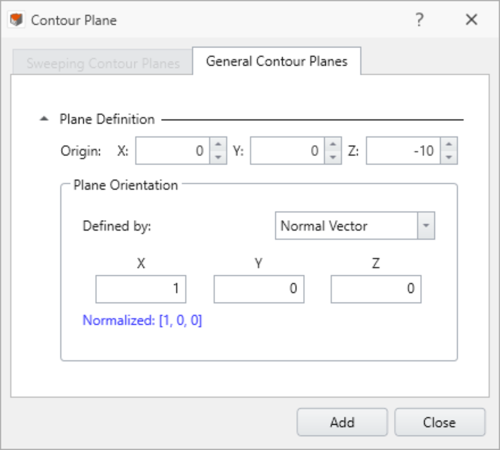
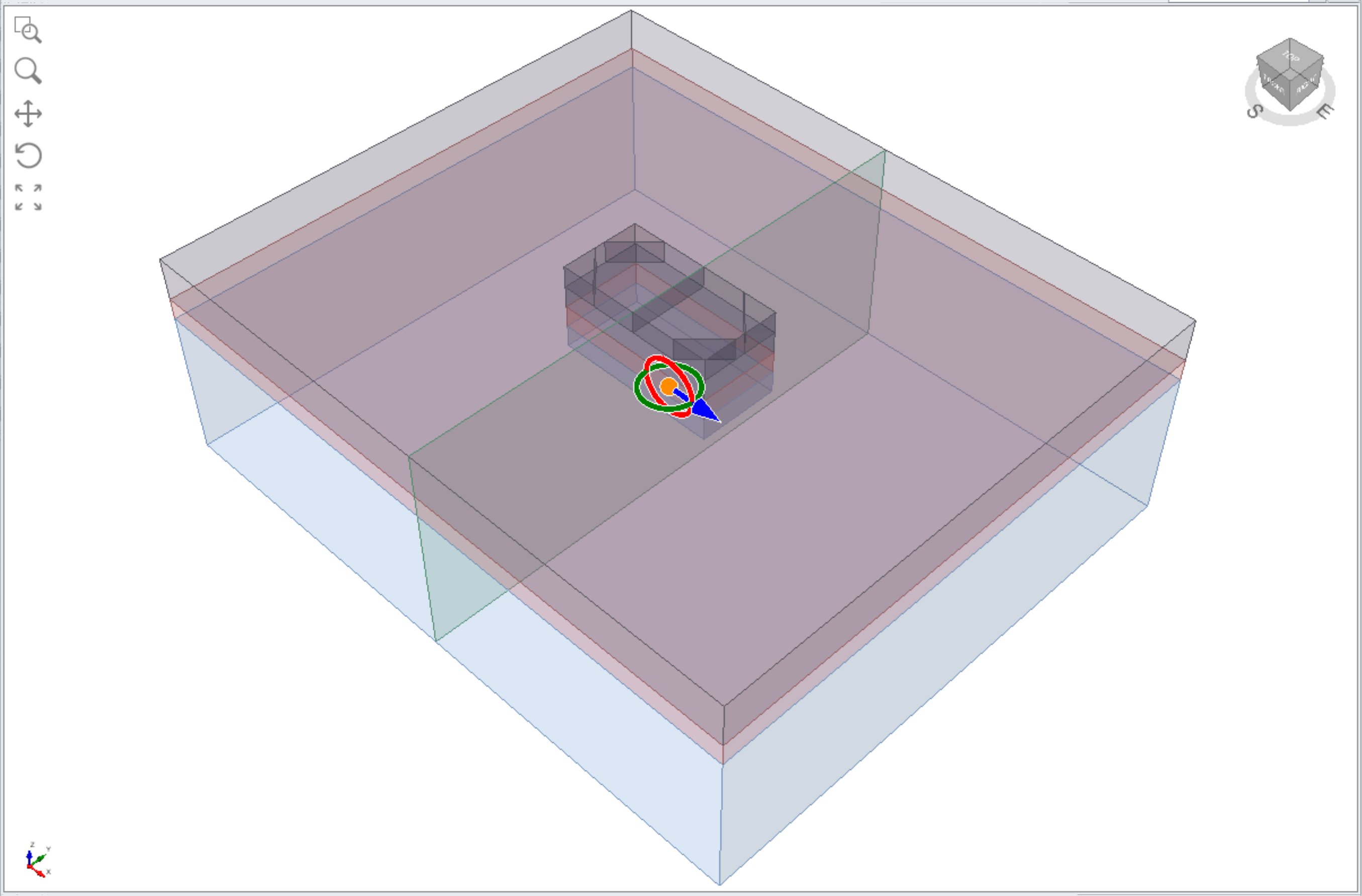
- Click Add and close the dialog
- Select: Interpret > Show Excavation Contour
- Select all external volume entities from the vibility tree
Adjust the transparency higher from the properties pane to visualize the displacement distribution more clearly
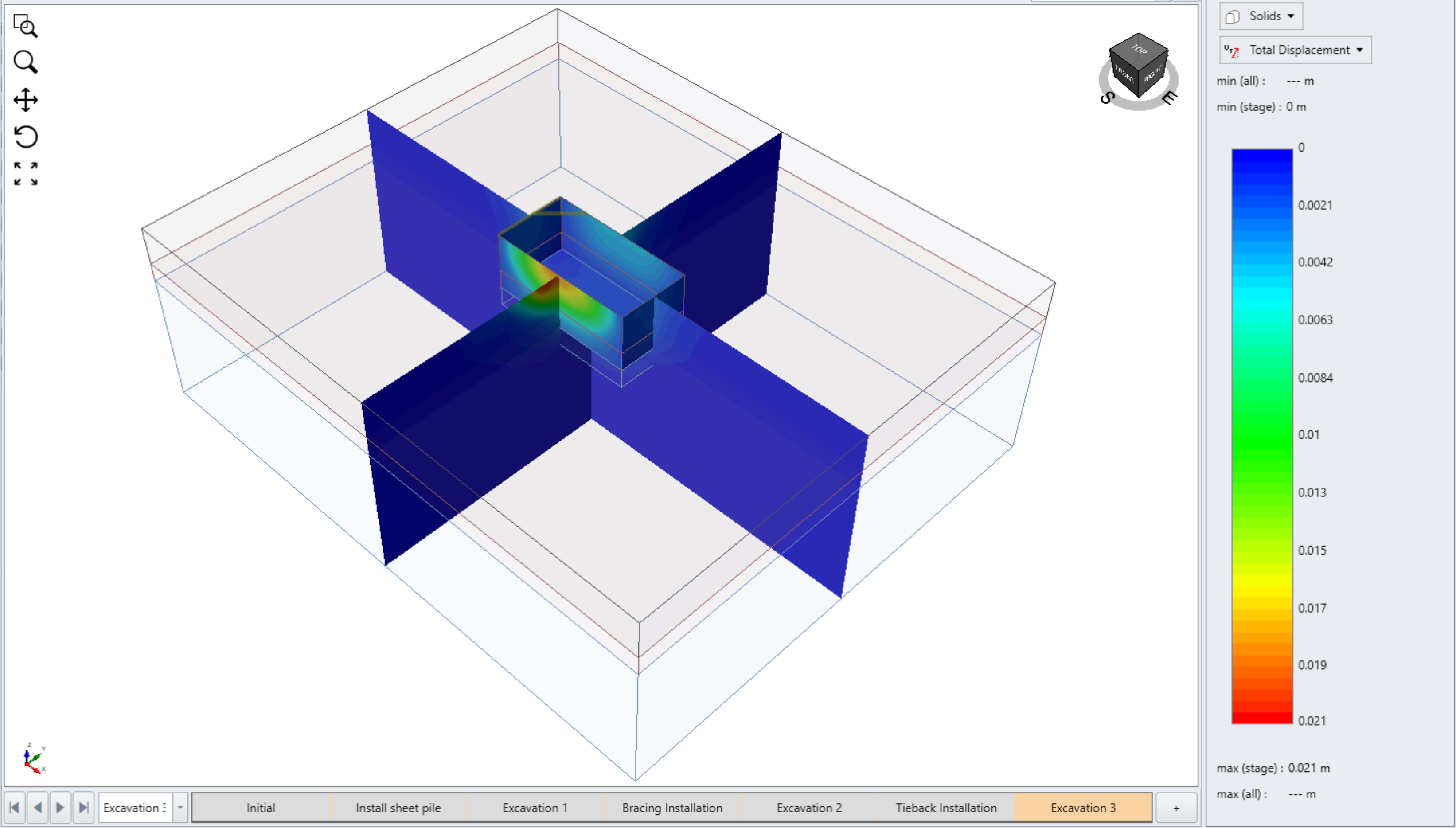
The result shows a concentrated deformation on the south side of the excavation due to the presence of building load.
10.2 BEAM RESULTS
- Hide all entities from the visibility tree but the excavation volumes
- Set the Legend to Beams & Piles and Axial Force
Below shows the axial force distributions of beams in Excavation 2 stage and Excavation 3 stage
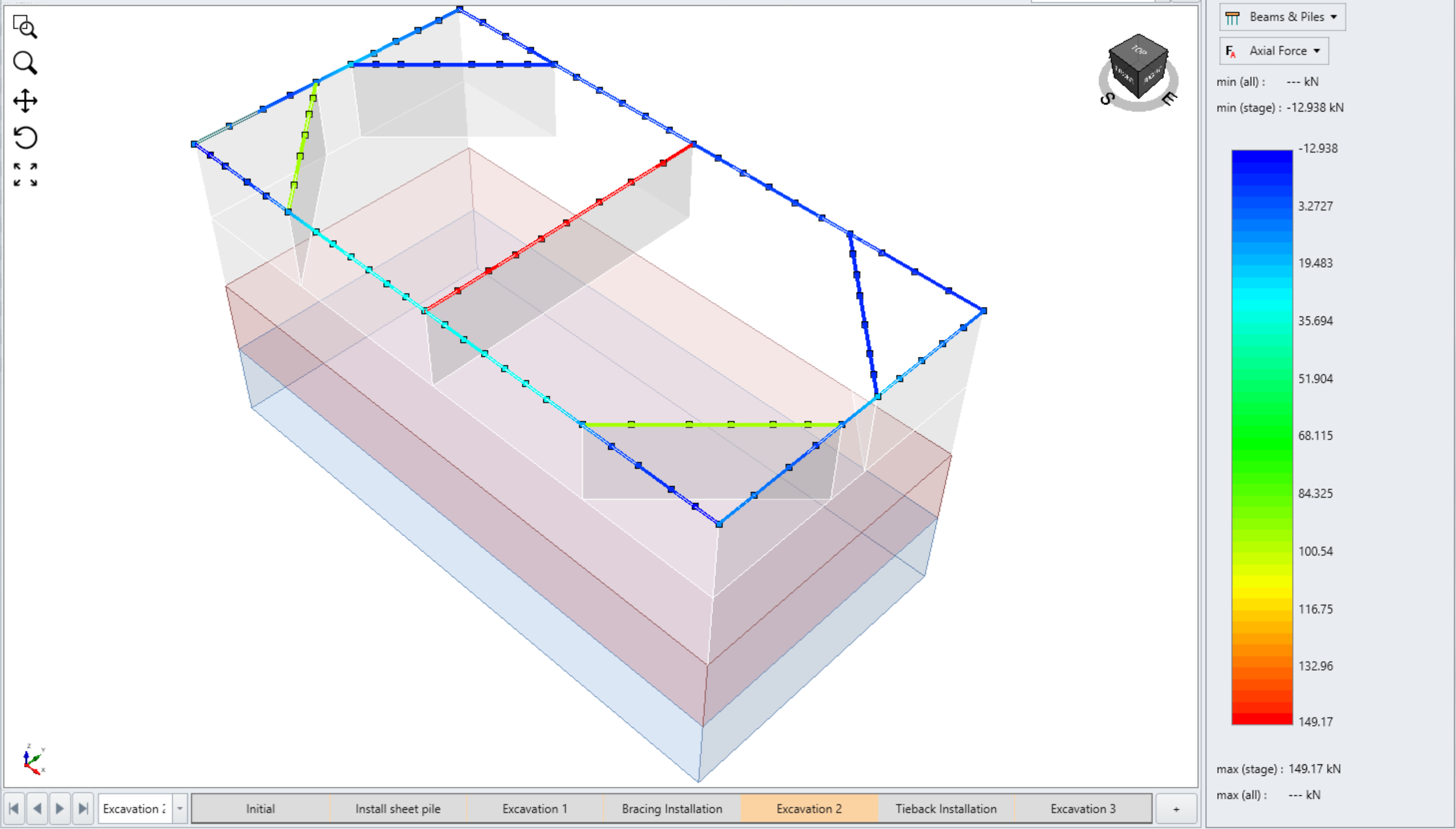
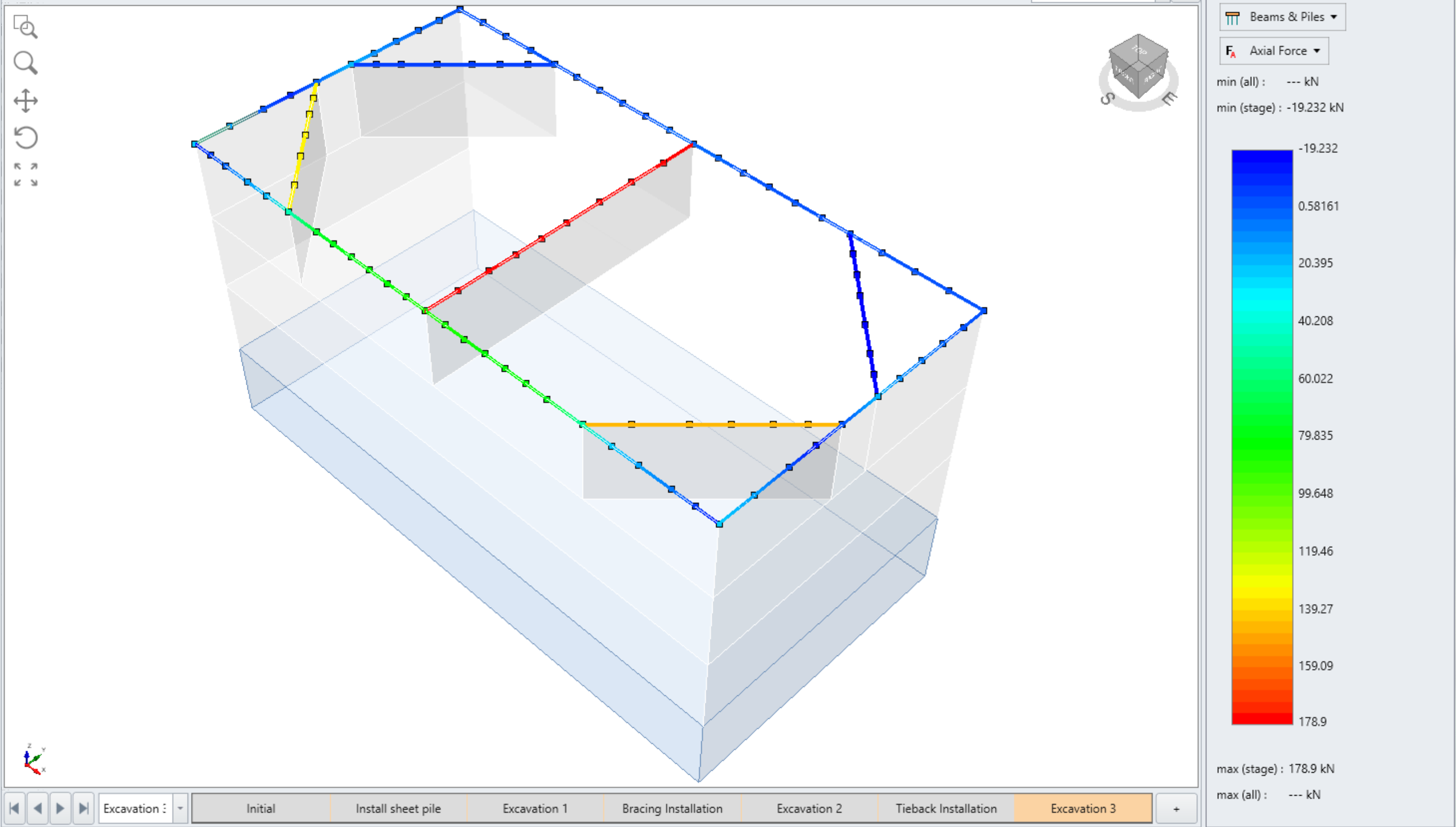
As demostrated from the displacement contour, higher load is induced in the beam approximate to the building load. Moreover, the excavation advancement results in a larger load within the beam with the highest concentration at the center.
10.3 BOLT RESULTS
- Set the Legend to Bolts and Axial Force
Select Excavation 3 stage
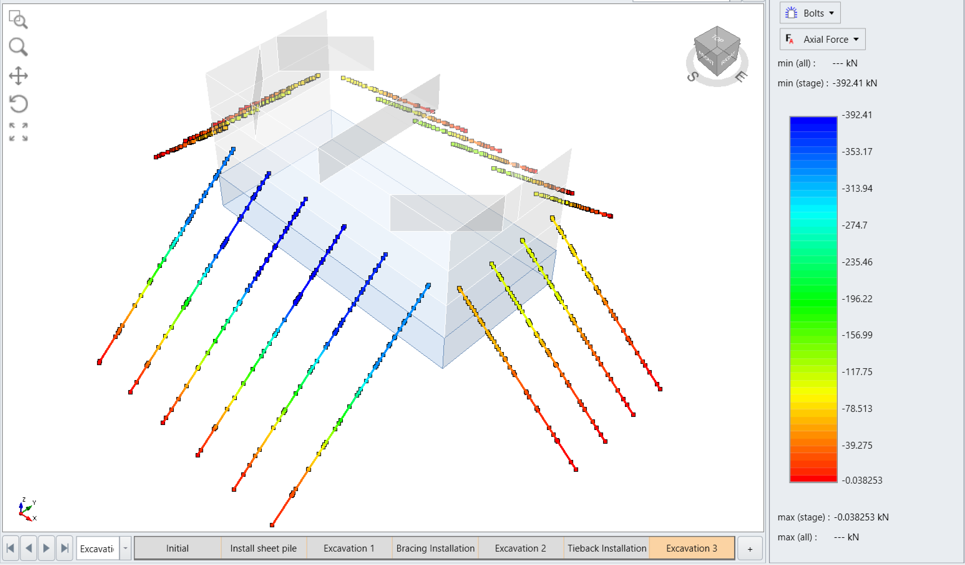
Select Bolt 2: Pattern Results from the Visibility Tree then Select point 4 from the Properties Pane then Select Graph Data
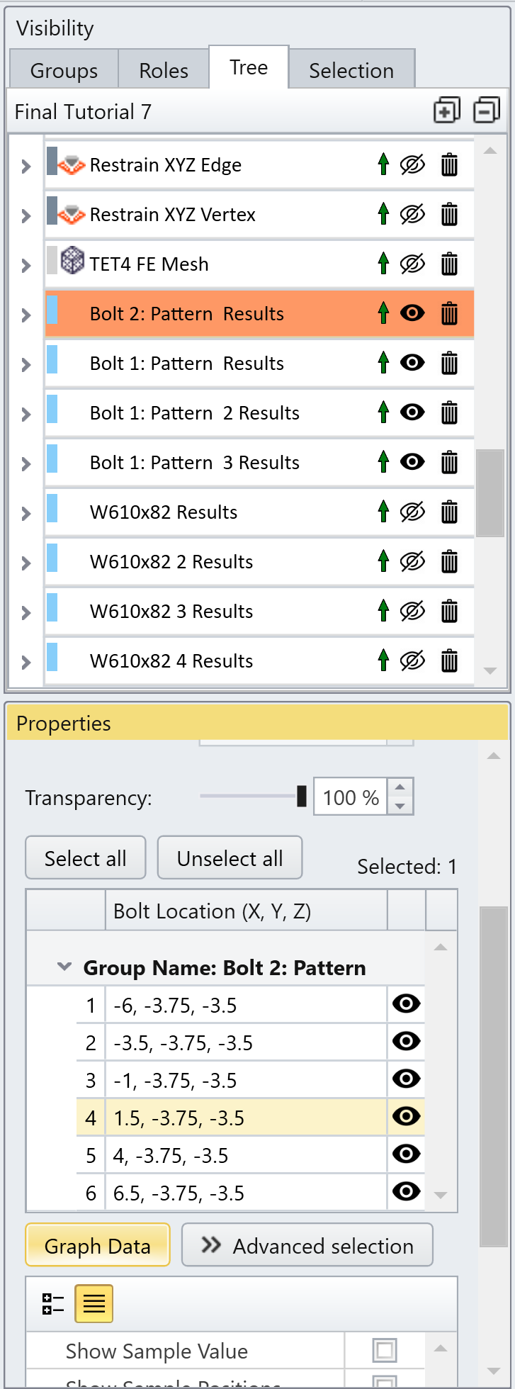
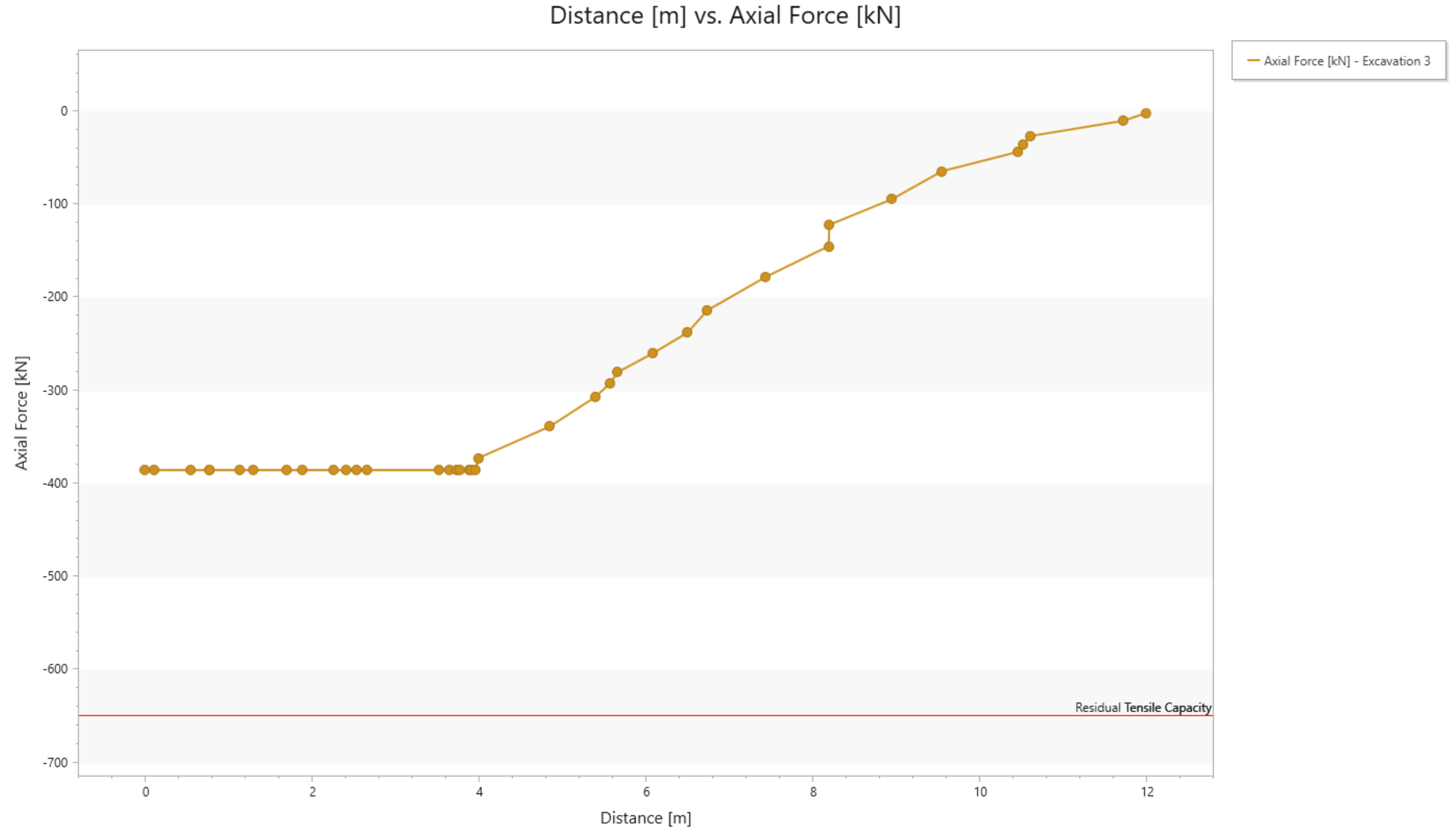
The graph shows a reduction in tension along the length of the bolt (away from the bolt head). It also demonstrates the bolt remaining intact (has not yielded), as the maximum applied axial force remains below tensile capacity.
10.4 WALL RESULTS
Set the Legend to Liners and Total Displacement
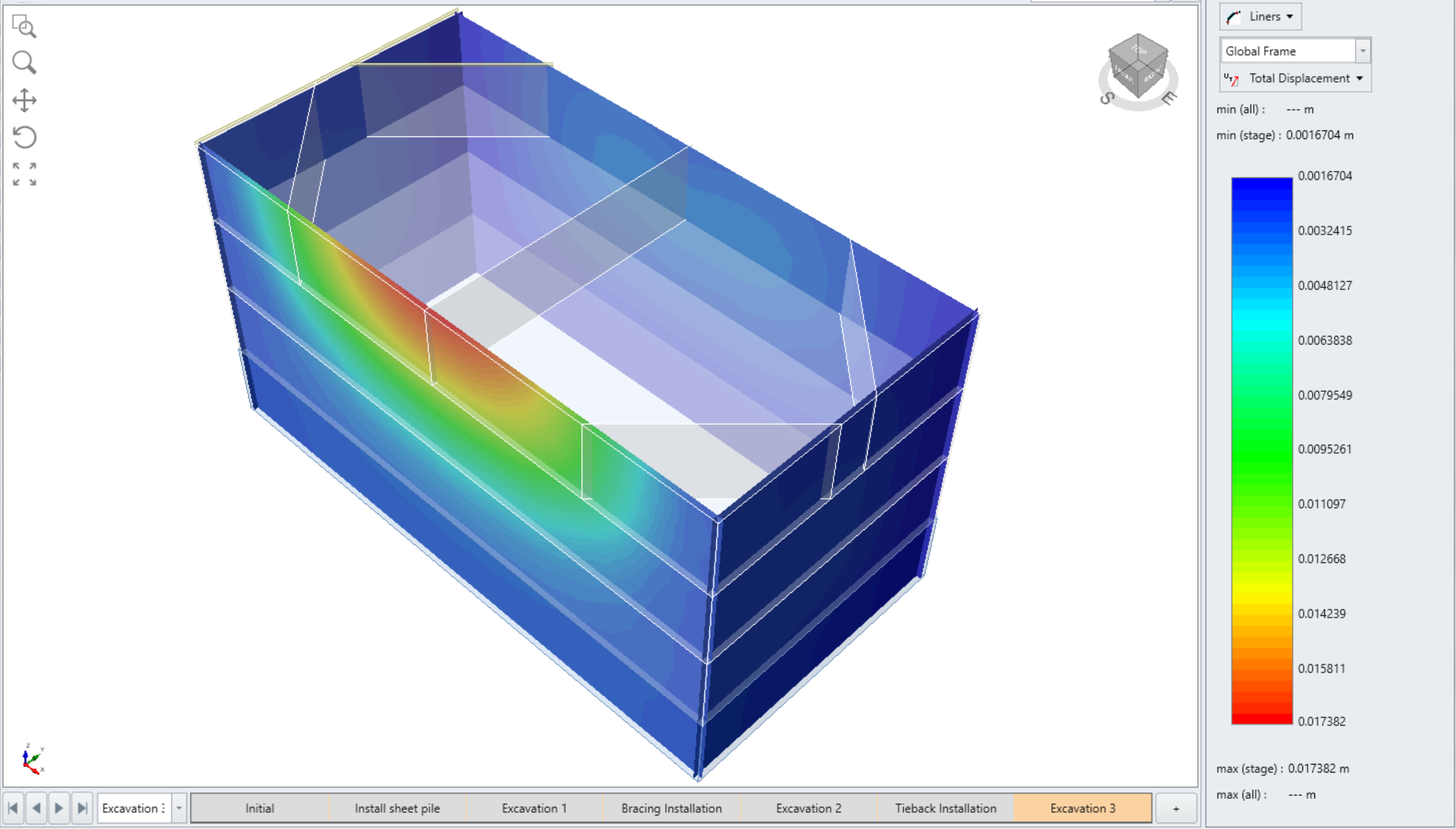
- Select SheetPile Wall from the Visibility Tree
- Right-Click > Hide All But Selected Geometry
- Select: Interpret > Queries > Add Liner Line Query To Surface
- Select the mid-point on the top then select the mid-point on the bottom
- Right-Click > Done
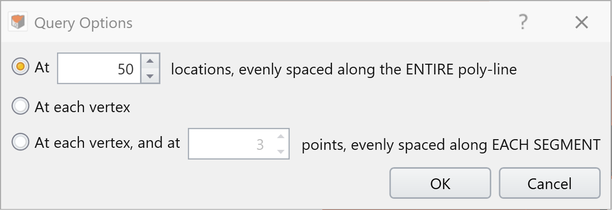
- Click OK
- Select the query line from the Visibility Tree
- Select Graph Data from the Properties Pane
- From the Chart Options, select Change Plot Data
- Primary Data: Y Displacement [m]
- Horizontal Axis: Distance [m]
- Secondary Data: Excavation 1, Excavation 2, and Excavation 3
- Click OK
- From the Chart Options select,
- Swap Axes
- Reverse X-Axis
- Reverse Y-Axis
- Min X Value: 0
- Max X Value: 8
- Min Y Value: 0
Max Y Value: 0.05
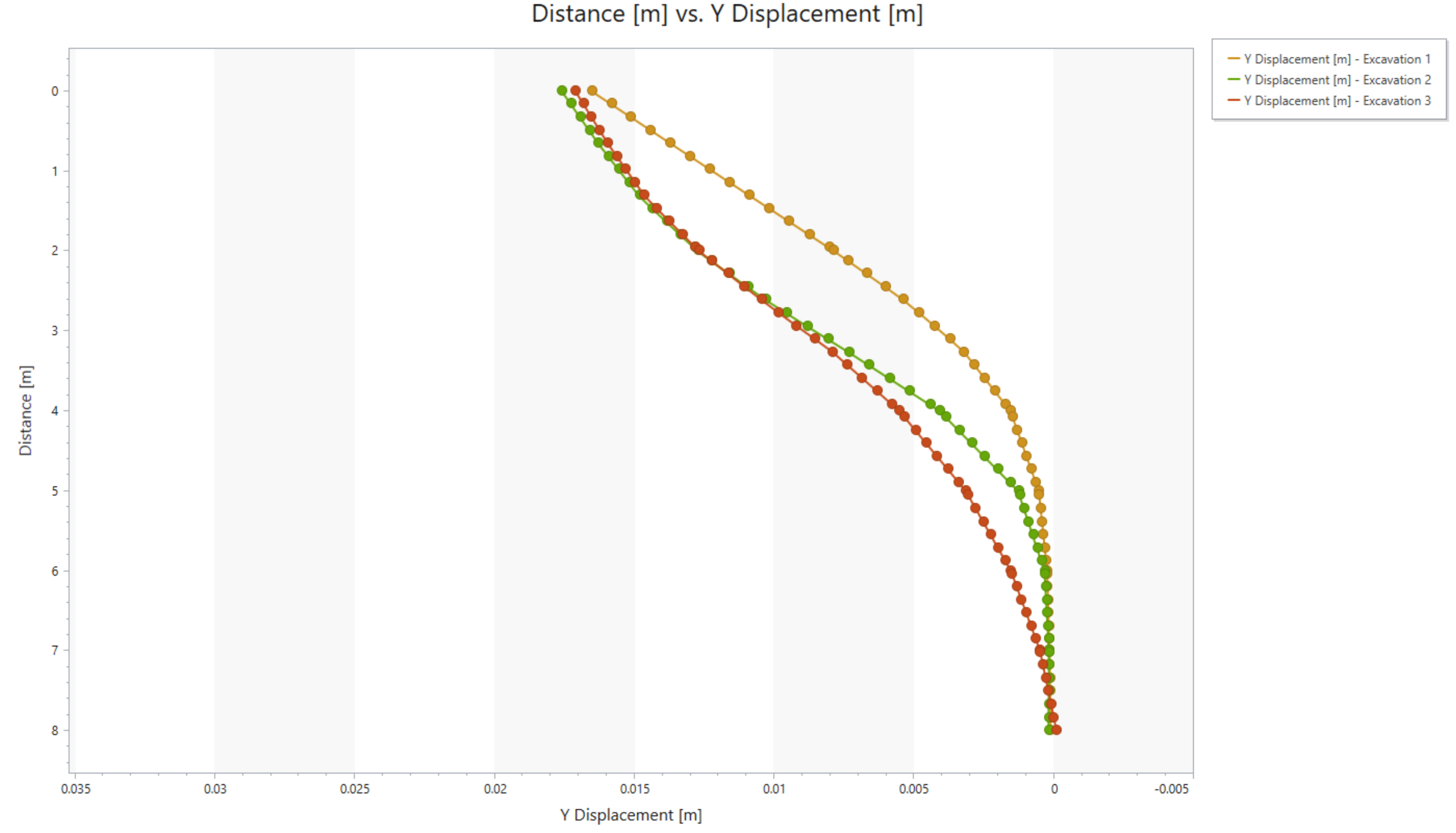
The graph shows the transverse displacement of the wall at each excavation stage. All three curves consistently shows the gradual reduction in displacement with depth. The deformation generally increases with deeper excavation, however; the liner deforms similarly between Excavation 2 and Excavation 3, due to the reinforcement from bolts.
- Select all the SheetPile Wall entities from the Visibility Tree
- Select: Interpret > Deformed Configuration, which renders the exaggerated deformation pattern of the wall
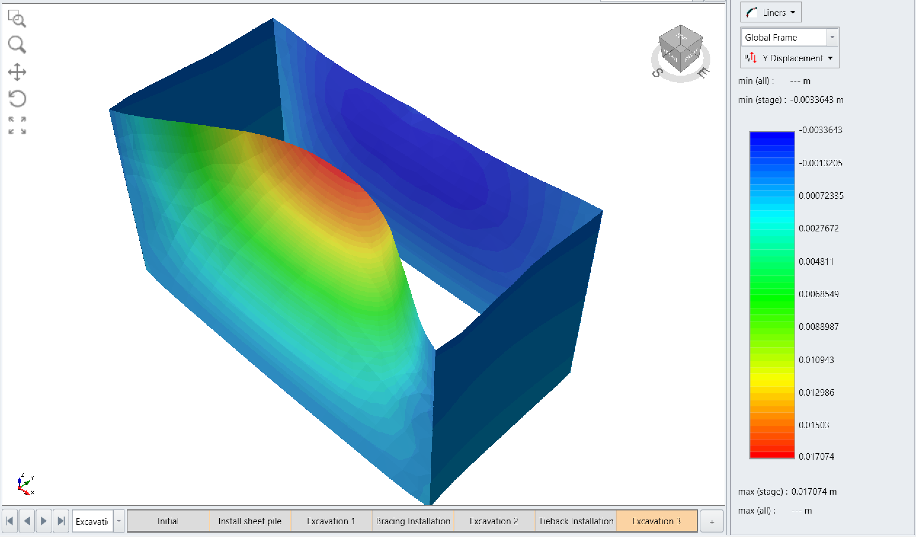
- Set the Legend to Liners and Y Displacement
- Select the SheetPile Wall Deformation entities from the Visibility Tree
- Right-Click > Hide All But Selected Geometry
In the Properties Pane, set Scale factor to 5 for each of the SheetPile Wall Deformation entities
This concludes the tutorial.