Referencing
Model registration refers to the process of aligning a 3D model with a given coordinate system. Two main approaches are provided:
- Ground Control Points
- Position information from a high-precision Global Navigation Satellite System
Ground Control Points
GCPs are points with known or surveyed coordinates in a world coordinate system. They must be clearly marked and easily identifiable in the captured images. The minimum number of GCPs required is three; however, depending on the spatial extent and complexity of the site, typically six to ten well-distributed GCPs are used. GCPs should be distributed across the entire area of interest and, if possible, also cover different elevations. Their positions are often determined using classical surveying instruments, which provide positional accuracy in the low-centimeter range. Each GCP must be visible in several images (at least three) taken from different angles. Therefore, GCPs should be clearly signalised, for example using high-contrast targets, spray-painted markers, or specialized patterns. MultiPhoto supports referencing using externally surveyed GCPs through two methods: Standard Referencing and Constrained Referencing.
Standard Referencing
MultiPhoto provides two different modes of Standard Referencing:
- Full Reference : The 3D model is s transferred into a superior co-ordinate system by using known co-ordinates of externally surveyed GCP (at least three) by similarity transformation.
- Single Point Mode: The 3D model is transferred to a co-ordinate system by using the co-ordinates of a single externally surveyed point (GCP) by similarity transformation. This mode is only available if the model is already referenced (EXIF GNSS positioning). It allows to transfer the 3D model to a user defined co-ordinate system.
Work flow
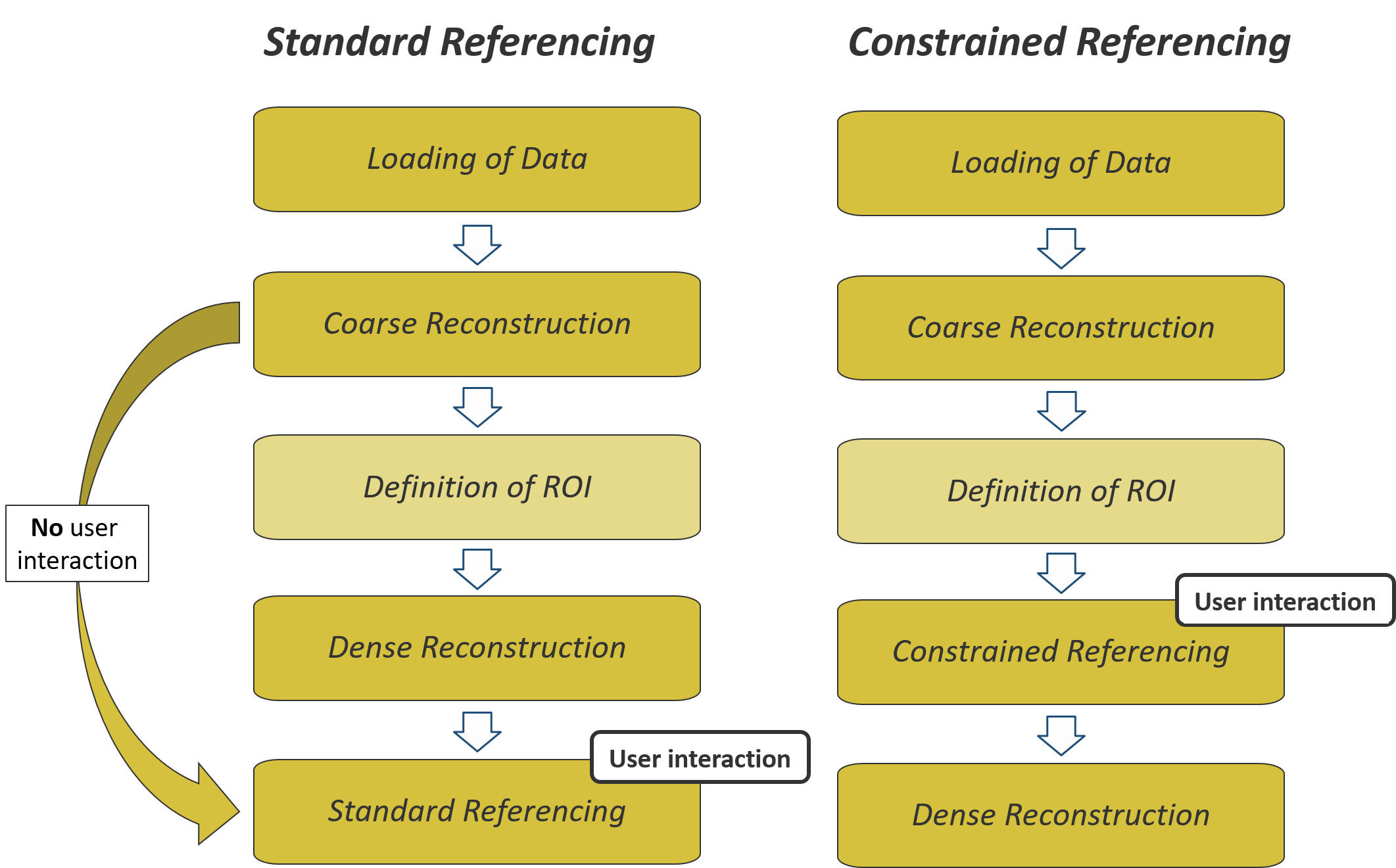
Once the data is loaded and reconstruction parameters are defined, the 3D model is generated fully automatically by MultiPhoto. In principle, no user intervention is necessary during the Coarse and Dense Reconstruction. The 3D model is referenced by the use of externally surveyed GCP (Standard Referencing) in a final step.
Constrained Referencing
Constrained Referencing is based on the optimization of the 3D model using the position of the externally surveyed GCP. Initial camera positions are re-adjusted and optimized. Generated 3D points of the dense point cloud (3D model) are forced into their position on the bases of the GCP co-ordinates.
Work flow
Constrained Referencing requires a step by step procedure for 3D model generation. Once the data is loaded, MultiPhoto generates the coarse 3D point cloud of the 3D model (Coarse Reconstruction). In an intermediate step, GCP constrained optimization of the model has to be performed by user interaction (Constrained Referencing). After optimization, the 3D model (“.jm3x”) is generated (Dense Reconstruction).
GNSS positioning
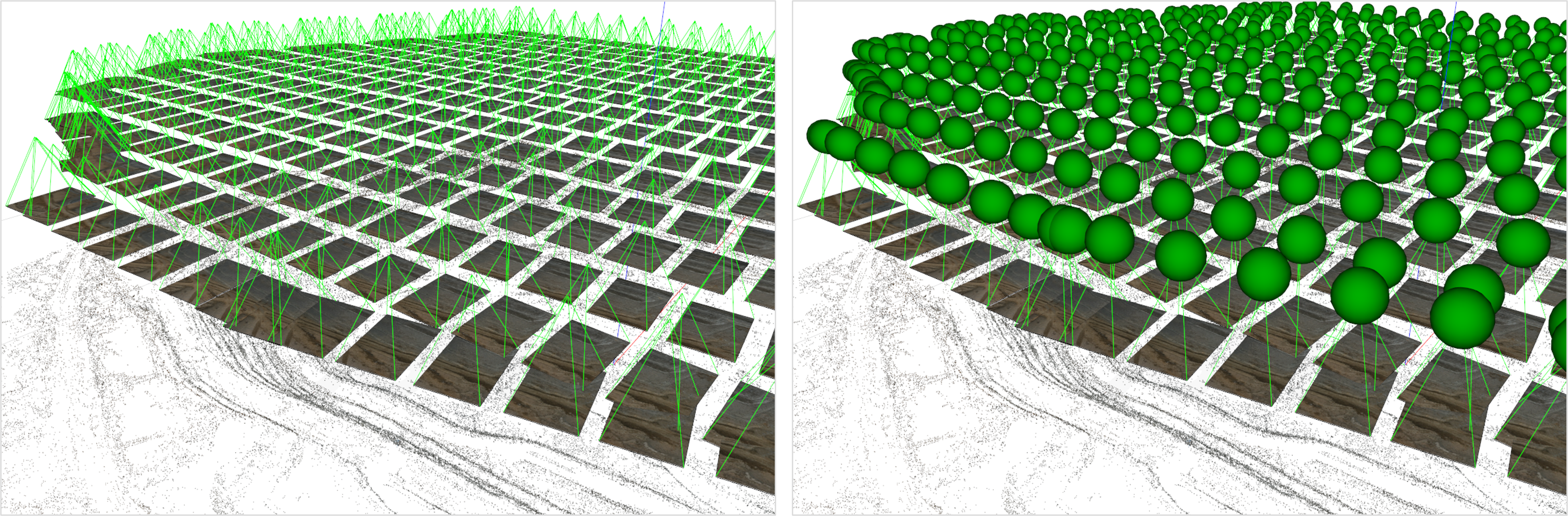
GNSS is used to record the locations of the camera from which the co-ordinates of the 3D model are extrapolated. It is available in two ways: (i) instantly while the photos are taken termed as Real-Time-Kinematic (RTK) and (ii) in a way where the standard positioning is upgraded afterwards using additional information from a second GNSS data source (Post-Processed Kinematic PPK). Both approaches can provide cm-accuracy for the camera locations.
CRS transformation
A Coordinate Reference System (CRS) transformation is the process of converting spatial data from one coordinate system to another. The transformation involves mathematical operations that adjust coordinates between the source and target CRS. In photogrammetry, CRS transformations are used to align locally generated 3D models with global coordinate systems using GCPs or GNSS data.
In MultiPhoto, CRS transformations are performed using the PROJ pipeline, which applies a sequence of coordinate operations such as axis changes, unit conversions, and datum shifts. This approach ensures accurate conversion between source and target co-ordinate systems.
PROJ-based CRS transformation is supported for all referencing procedures provided, including Standard Referencing, Constrained Referencing, and GNSS-based positioning. Using this approach, local photogrammetric models can be integrated with global or project-specific coordinate systems for mapping, analysis, and other geospatial applications.