Data Input and Coarse Reconstruction Overview
The start window “Configure Project” allows for loading images for processing as well as defining parameters for the Coarse and Dense Reconstruction. Additionally, the user can modify the camera calibration of the photos, visualize positional information stored in the photos, and enable GNSS-based positioning to incorporate georeferenced coordinates.
User interface
The user interface “Configure Project” comprises several features shown below. On the left hand side, it consists of the list of loaded images and functions for defining and modifying camera calibration data, and visualising GNSS positional (GPS) information if available. On the right hand side, it consists of a viewer showing a preview of the selected image and functions for defining projects settings. In addition, GNNS positional referencing possibilities (including CRS transformation) as well as settings for the Coarse Reconstruction and Dense Reconstruction are available.
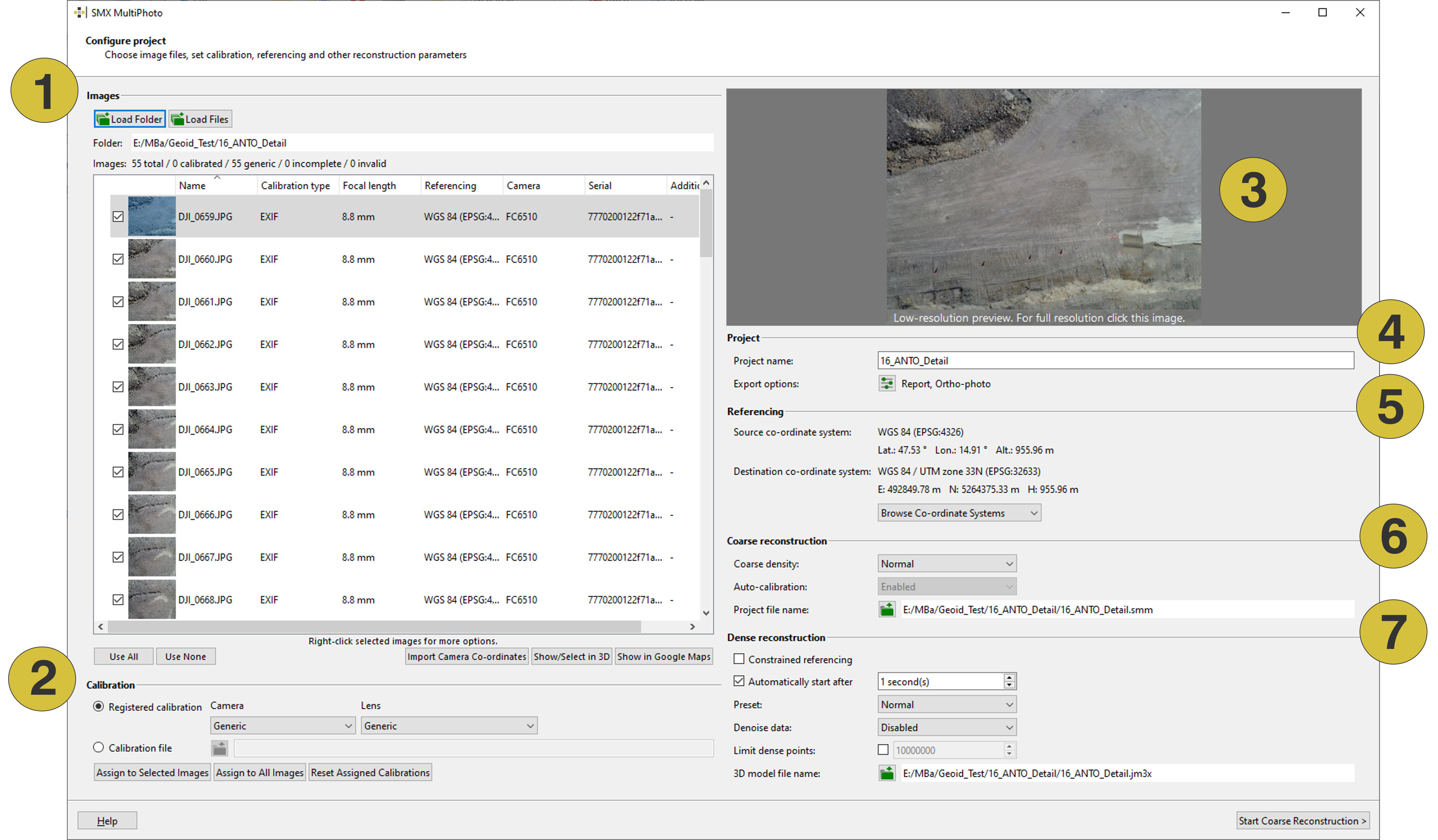
- Image data
- Calibration
- Image preview GPS data
- Project settings
- Referencing (GNNS positioning)
- Coarse Reconstruction settings
- Dense Reconstruction settings
Features
Images
- Load Folder - Opens a dialog to load a series of photos (stored in one folder)
- Load Files - Opens a dialog to load photos individually
The list of the loaded images (number 5) shows the following information for each entry:
- Picture thumbnail
- Name of the image
- Calibration type:
- EXIF - MultiPhoto uses calibration information from the “.exif” file (extended image information)
- Specific Calibration Name - MultiPhoto uses calibration information from a registered calibration installed via the Start Window Settings dialog or uploaded by clicking the “Calibration File” icon
- Focal length
- Referencing - GNSS positioning and co-ordinate system
- Camera information
- Serial number
- Additional information
The following information on the loaded images is given at the top of the list:
- image(s): total number of images
- calibrated: number of images with registered calibration
- generic: number of images with calibration information gained from the “.exif” file (extended image information)
- incomplete: number of images without calibration (neither registered calibration nor calibration information from the “.exif” file is available)
- invalid: number of defective images
- Use All - Selects all photos from the list of loaded images for reconstruction
- Use None - Deselects all photos from the list of loaded images for reconstruction
- Import Camera Co-ordinates - Imports camera position from a text file
- Show/Select in 3D - Camera position shown in a 3D viewer. The dialog supports the selection of images that should be used for 3D model generation directly in the viewer.
- Show in Google Maps - The location of the images are shown in Google Maps
A click on the right mouse button on a loaded image in the list opens the context window providing following options:
- Use Selected - Enables the checkbox in front of individual images; the image will be included in 3D model generation
- Don´t Use Selected - Disables the checkbox in front of individual images; the image will be excluded in 3D model generation
- Remove Referencing Data - Excludes the GNSS measurements of individual images. The image is included in 3D model generation.
- Show in Google Maps - Shows the location of the individual images in Google Maps
Calibration
- Registered calibration - Allows using a registered (installed) or generic calibration
- Calibration File
 - Opens a dialog for selecting a calibration file (“cam.dat” file)
 - Assign to Selected Images - Assigns the selected calibration to selected images
- Assign to All Images - Assigns the selected calibration to all images
- Reset Assigned Calibrations - Removes the calibration assigned to all images
Image viewer
The image viewer allows a detailed view of the selected image and comprises two scroll bars and a toolbar supporting the image display.
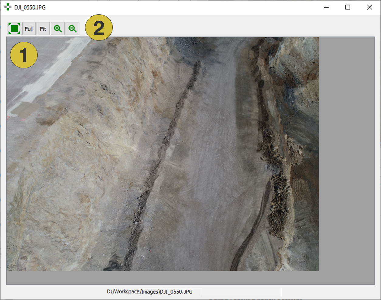
- Viewer
- Toolbar with zoom functions
Project Settings
- Project name - Title of the project (optional). Updating the project name updates also the Project File name and the Output File name.
- Export options
 - Opens a dialog for selecting export possibilities; i.e. the reconstruction report (“.pdf”), ortho-photo (“.png”), GeoTIFF (“.tif”) and “.obj” export.
Referencing
(only if positional information is available)
- Source co-ordinate system The Source co-ordinate system refers to the original coordinate system in which the input data are defined. The software reads these original coordinates and uses them as a reference for positioning the images or model. For example, GNSS data is often recorded in a global geographic system such as WGS84 (latitude, longitude, altitude).
- Destination co-ordinate system The Destination co-ordinate system is the coordinate system into which your data is transformed during processing.The input data are converted from the Source co-ordinate system into this system.
- Autodetect The UTM zone is auto-detected from the referencing information of the images (WGS 84).
- Browse – Co-ordinate System - The user selects a user defined co-ordinate system. The dialog “Select Co-ordinate Reference System” appears which allows for the selection of a specific co-ordinate system. The 3D model is transferred automatically into the desired co-ordinate system during 3D model generation.
Coarse Reconstruction Settings
- Coarse Density
- Normal: Normal feature density; used for photos with reasonably high overlap
- High: High feature density; used for photos with low overlap or strong angular changes
- Auto-Calibration Enables or disables auto-calibration: Auto-calibration is mandatory if uncalibrated photos are used (generic entry). If photos from pre-calibrated cameras are used (calibration entry), auto-calibration can be enabled or disabled.
- Project File Name Opens a dialog for entering the directory and name of the generated Project File (“.smm” file)
Dense Reconstruction
- Constrained Referencing - Enables Constrained Referencing
- Automatically start after … - The reconstruction process continues automatically after a user-defined time from Coarse Reconstruction into Dense Reconstruction, if no user interaction has be registered by the software during the waiting period. Enabling also activates Dense Reconstruction settings (see below).
- Preset - Defined the final 3D model resolution (mesh as well as texture resolutions
- Fast: Preset for fast Dense Reconstruction; Low resolution topography, low resolution texture (for e.g. volume calculations)
- Normal: Default Dense Reconstruction settings; Medium resolution topography, high resolution texture (for e.g. blast design)
- High: Preset for high detail Dense Reconstruction settings; High resolution topography, high resolution texture (for e.g. rock mass characterisation, fragmentation analysis)
- De-noise data
- Disabling noise suppression. The point cloud should be used for applications with standard requirements on surface quality. No special geometric resolution preset is needed. (e.g. for blast design, volume calculations)
- Enabling noise suppression. The point cloud can be used for application with enhanced requirements on surface quality.
- Limit dense points - Defines the upper limit of points which generates the reconstructed 3D model. Default value is 10.000.000 points.
- 3D model file name - Opens a dialog for entering the directory and name of the final 3D model (“.jm3x” file)
- Start Coarse Reconstruction - Starts the reconstruction process and continues to the next step