Constrained Referencing with GCP
For the description of user interfaces and corresponding features of the individual steps refer to topics Data input and Coarse Reconstruction, Select Scene Region of Interest and Dense Reconstruction.
Constrained referencing may be applied with an existing Project File. The file can be loaded by the selection “Perform constrained referencing” icon when starting MultiPhoto.
Data input and Coarse Reconstruction
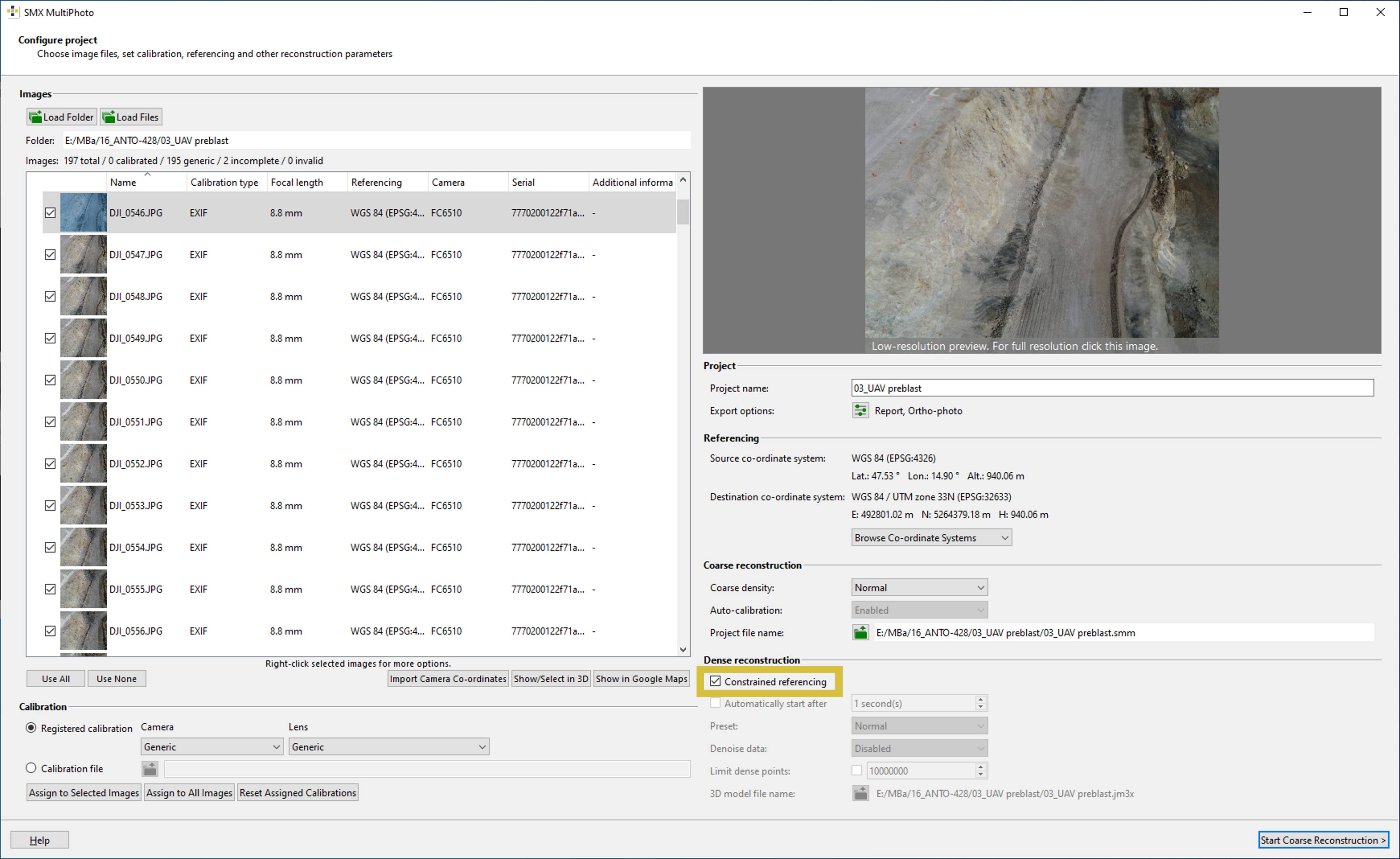
- Load image data by clicking the “Load folder” or “Load Files” icon. A progress window appears during scanning and loading.
- Check if all required images for processing are selected. If not, adapt the list of images by enabling or disabling the checkbox in front of the images, respectively, or use the buttons “Use all” or “Use none”.
- Check if the pictures for processing have a generic (EXIF) or calibration entry assigned.
- If GNSS positional information is available, the user can check the relative camera positions and geographical position by clicking the “Show/Select in 3D” button. In addition, the dialog supports the selection of images directly in the 3D viewer by using the computer mouse (see Chapter 6.3).The position of the images can also be displayed in Google Maps using the “Show in Google Maps” button.
- Enter a project name and select the desired export possibilities by clicking the “Export Options” button. The export start automatically when leaving the MultiPhoto after 3D model generation.
- Choose Coarse Reconstruction settings “Normal” (default).
- Rename the Project File (“.smm”) and select the directory to save by clicking the “Project File Name” icon in General Settings.
- Enable the reference mode Constrained Referencing
- Start the reconstruction process by a click on the “Start Coarse Reconstruction” button. The progress window reveals the current status of reconstruction including a live display.
The Automatically Continue Reconstruction does not feature the use of Constrained Referencing .
Select Scene Region of Interest
The definition of a ROI is optional. It is skipped by clicking the “Next” button. If no ROI is defined, the outlined coarse 3D model is used for Dense Reconstruction.
Standard operating procedure:
- Check the coarse 3D point cloud for plausibility
- Define Region of Interest
- using the sliders next to “Camera distance based” or “Scene centre based”
- directly in the viewer using a boundary polygon:
- Click on the “Select” button
- Click with the left mouse held down in the 3D viewer and draw a polygon. The polygon should define the desired ROI.
- Relieve the mouse button and the point cloud is reduced to the outlined ROI.
- The ROI can be deleted with a click on the “Clear” button
- Click on the “Next” button to continue to the next step
Press “Shift” while keeping the left mouse button pressed to draw a straight line.
Referencing
Please refer to Chapter 9.3 for importing GCP coordinates, whether generic or user-specified, and, if required, including CRS transformation.
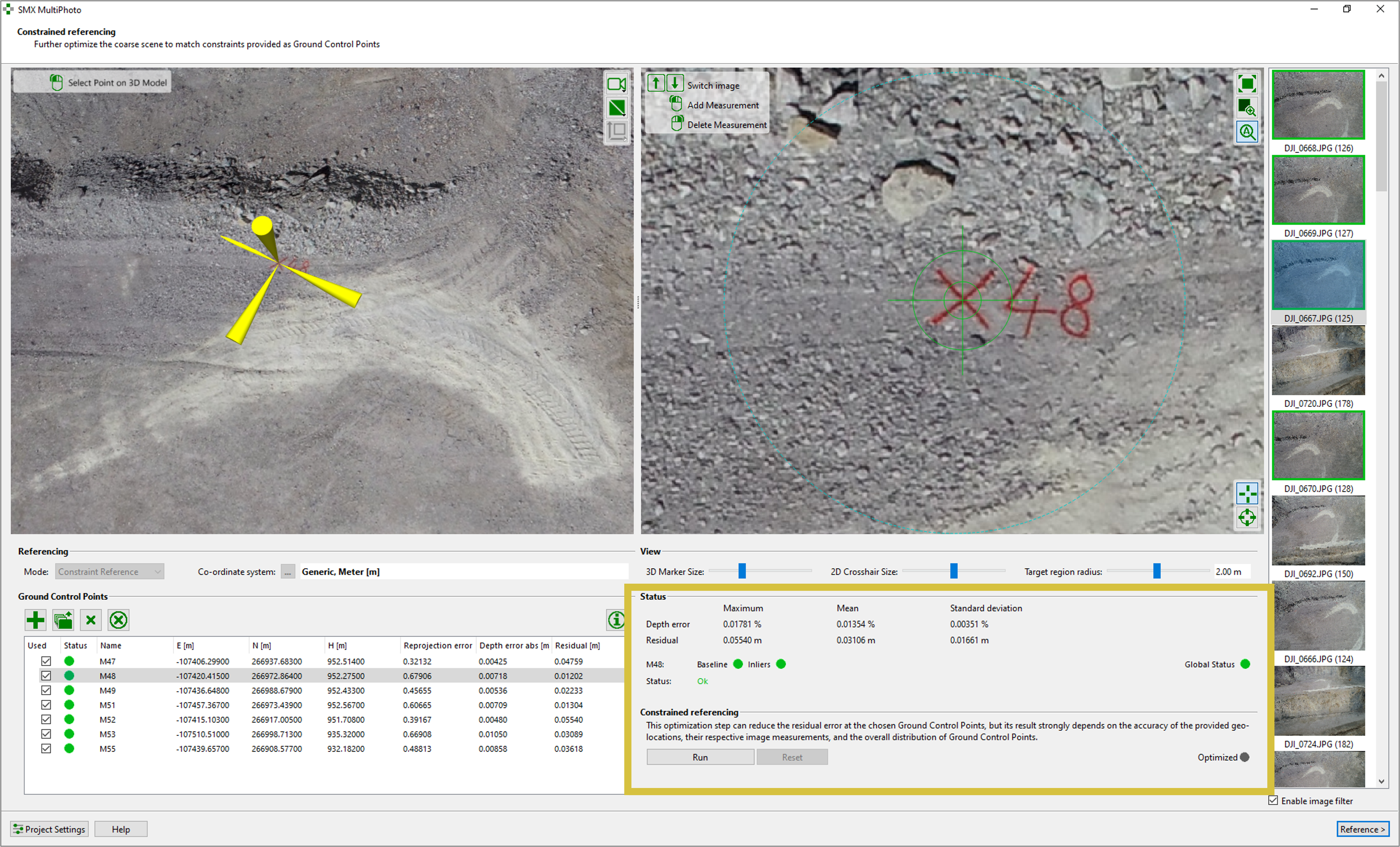
The interface of Constrained Referencing is similar to the Referencing interface whereby two additional feature are provided:
- Run - Runs GCP optimization
- Reset - Resets GCP optimization
Standard operating procedure
- Add GCP by
- clicking the “Add GCP” icon and entering the name and co-ordinates in the GCP list.
- clicking the “Read GCP from Text File” button and choose the text based files(“.csv”, “.txt”, “.dat”, “.prt”).
- Activate one GCP in the list and localize its position in the 3D viewer by clicking the left mouse button. The list of reference images is updated and the active image is shown in the viewer.
- Choose the “Manual Target Mode” icon or the “Automatic Mode Icon” and centre the target by clicking with the mouse in the viewer. For locating the target discs the image should be zoomed as much as reasonable for visual interpretation. Check the position of the center by changing the size of the reticule. The reticule is well-centered if the circles touch the target’s boundary simultaneously at two opposing points and in two perpendicular directions.
- Choose at least 2 images (3 or more are recommended) showing the same GCP and click the center of target. The status signals Baseline and the Inliers turn into green and the error of re-projection and depth is displayed in the GCP list.
- Activate the next GCP in the list and repeat steps 2 – 4. Continue until all GCP positions are localized.
- Check the Status Information (green status signals) and enable referencing by clicking the “Run” button. The Optimized signal turn into green.
- Check the error statistics and confirm referencing by clicking the “Reference” button.
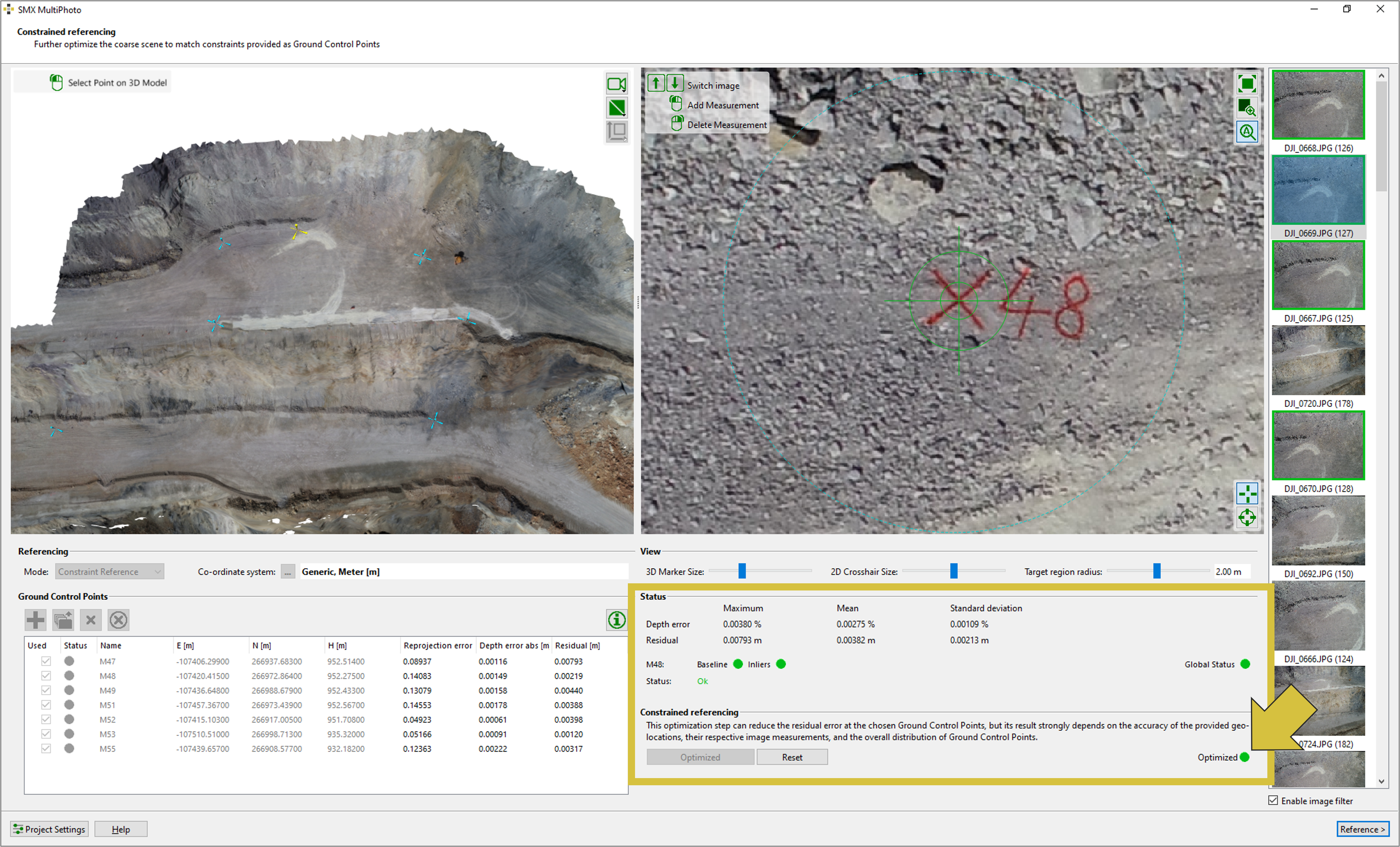
A defined ROI does not limit the localization of GCP in the images. GCP may be located in images outside the generated 3D model by deactivating the “Enable image filter” checkbox. The whole set of images used for the generation of the 3D model, including images for Coarse Reconstruction, will be listed. The user has to select the images showing the GCP manually from the list.
Dense Reconstruction
- Check the coarse 3D point cloud for plausibility
- Choose the Dense Reconstruction mode - Fast, Normal or High
- Disable ore enable “De-noise depth maps”
- Optionally, limit the number of 3D points by enabling the checkbox “Limit Dense Points”.
- If necessary, rename and select the directory of the output file (“.jm3x”) by clicking the “Output File Name” icon
- Start the reconstruction process by a click on the “Start Dense Reconstruction” button. The appearing progress window shows the current status of reconstruction.
- Inspect the 3D model in the 3D viewer.
- Close the MultiPhoto by clicking the “Exit” button.