Alignment of the Reference Plane
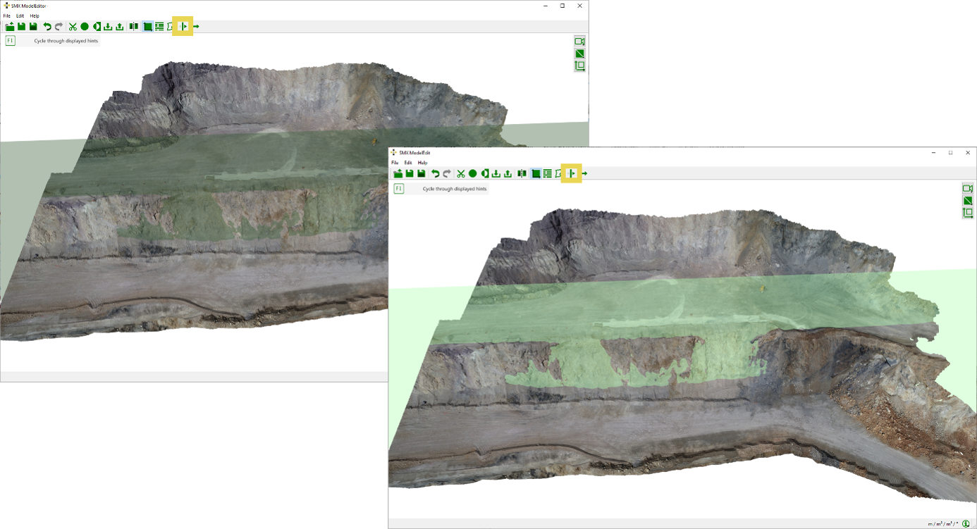
The Reference Plane is used as the basis for measurements in the Analyst, e.g. depth colouring (see the corresponding user guide). The Reference Plane is set automatically after 3D model generation as the plane having the mean orientation and position of the 3D model. It is visualized in the 3D viewer by clicking the “Show Reference Plane”  button. The position of the plane can be modified interactively by defining a user-defined region directly on the 3D model or by entering measured coordinates (x, y, z or easting, northing, height) and slopes (azimuth and inclination).
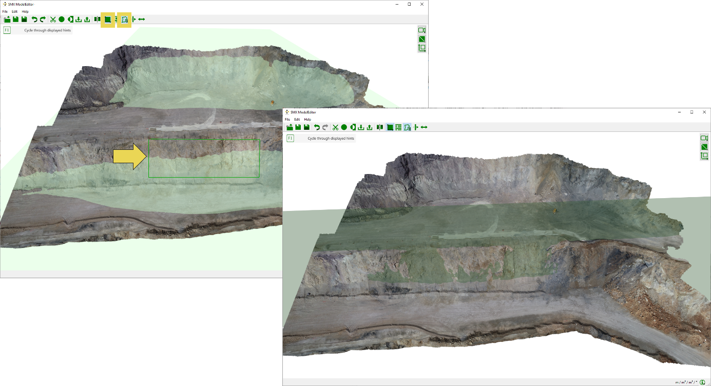
Set Reference Plane from Region
- Click on the “Set Reference Plane from Selection”
 icon in the toolbar and mark a polygonal region on the 3D model. The Reference Plane is defined by the set of points enclosed by this region.
 - The Reference Plane will be calculated and immediately set after releasing the mouse .
Set Reference Plane from co-ordinates
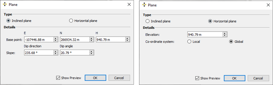
- Select “Set Reference Plane”
 in the Tools pane
 - Enter values for positioning the Reference Plane in the appearing dialog:
- inclined plane
- co-ordinate system [easting, northing, height]
- slope (dip direction and dip angle)
- horizontal plane
- elevation
- co-ordinate system [local or global]
- inclined plane
Adjust Reference Plane
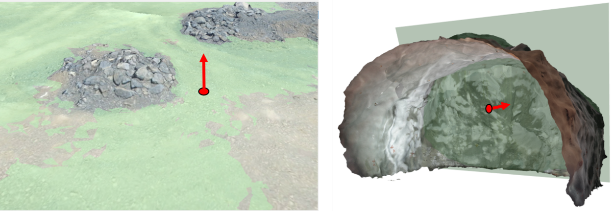
- If necessary, adjust the orientation of the upward normal vector of the Reference Plane by a click on the “Flip Normal”
 icon in the Tools pane. The orientation of the normal vector is indicated by a green shading of the Reference Plane. Light green shading means that the observer faces the upward normal vector while dark green shading means the upward normal vector points away from the observer.
 - The Reference Plane can be moved by clicking the “Move Reference Plane”
 icon in the menu bar and clicking the desired position on the 3D model.