5 - Field Stress
This tutorial demonstrates the Field Stress option in UnWedge.
The default UnWedge analysis is based upon the assumption that the wedges are subjected to gravitational loading only (i.e., self-weight of the wedges). The actual stress field in the rock mass surrounding the excavation is not taken into account. While this assumption leads to some inaccuracy in the analysis, the error is generally conservative, leading to a lower Factor of Safety. The Field Stress option in UnWedge allows you to include the effect of in-situ stress (clamping stress) on the wedge Factor of Safety. In general, this has a tendency to increase wedge Factor of Safety, although this depends on the wedge geometry and field stress orientation. By default, the reported Factor of Safety (with field stress) will always be greater than (or equal to) the Factor of Safety without considering field stress.
Topics Covered in this Tutorial:
- Stress Analysis Overview
- Defining Field Stress
- Factor of Safety with Field Stress
- Viewing Stress Contours
- Stress Contour Data Tips
- Advanced Stress Options
Finished Product:
The finished tutorial can be found in the Tutorial 05 Field Stress Final.weg5 file located in the Examples > Tutorials folder in your UnWedge installation folder.
1.0 Introduction
When the Field Stress option is applied in UnWedge, a boundary element stress analysis is automatically performed prior to the wedge stability calculation. This determines the elastic stress distribution around the excavation, which is used to compute the actual stress distribution on each wedge plane. The general features of the stress analysis implementation are as follows:
- The field stress orientation and magnitude are defined in the Field Stress dialog. You may choose either a constant or gravitational far-field stress.
- Based on the field stress parameters, UnWedge will carry out a boundary element stress analysis around the excavation. The boundary element method assumes linear elastic behaviour (i.e., plasticity and localized failure is not accounted for in this type of analysis).
- The boundary element stress analysis used in UnWedge is based on the analysis engine used in the Rocscience program EX3.
- The boundary element stress analysis in UnWedge uses the Complete Plane Strain formulation. This means that the principal stress orientations do not have to be aligned with the excavation axis. Although the excavation model is 2-dimensional, the defined Field Stress and the stress analysis results are three-dimensional.
- The stress analysis determines the distribution of stresses around the Opening Section assuming an infinitely long excavation in the axis direction.
- The stress analysis DOES NOT analyze the stress distribution around the ends of the excavation. Therefore, the results of using Field Stress can only be applied to the Perimeter Wedges and does not apply to the End Wedges.
- Based on the results of the stress analysis, UnWedge determines the actual distribution of stress on each wedge face (Perimeter Wedges only) and includes this stress in the stability calculations.
2.0 Model
- If you have not already done so, run the UnWedge program by double-clicking the UnWedge icon in your installation folder or by selecting Programs > Rocscience > UnWedge > UnWedge in the Windows Start menu. When the program starts, a default model is automatically created.
If the UnWedge application window is not already maximized, maximize it now so that the full screen is available for viewing the model.
To begin this tutorial:
- Select: File
 > Recent Folders > Tutorials Folder
 - Read in the file Tutorial 05 Field Stress_initial.weg5
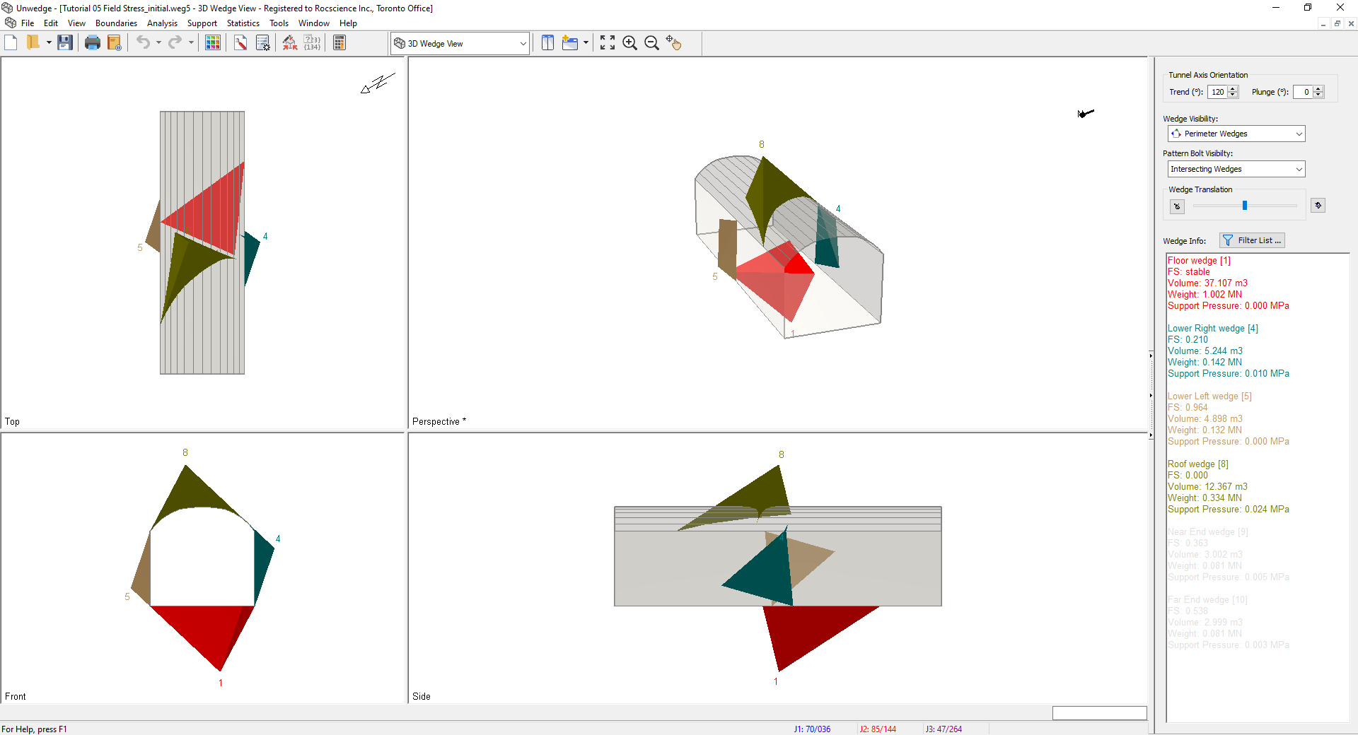
The model represents a horizontal tunnel with an axis orientation of Trend = 120, Plunge = 0. Notice the four Perimeter Wedges, and Factor of Safety values:
- Lower Right Wedge (FS = 0.210)
- Lower Left Wedge (FS = 0.964)
- Roof Wedge (FS = zero)
- Floor Wedge (stable)
The model currently does NOT have Field Stress defined, therefore the wedges are subjected to gravitational loading only, due to the self-weight of each wedge.
3.0 Field Stress
We will now define Field Stress and observe the effect on the wedge Factors of Safety.
To define Field Stress:
- Select Field Stress
 on the toolbar or the Analysis menu.
You may see a Warning dialog. The dialog message is a reminder that the Field Stress option should always be considered an advanced user option, and results should be carefully evaluated. For conservative design purposes, it is best to design on the basis of NO Field Stress effect.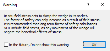
- Read the message and select OK.
The Field Stress dialog appears.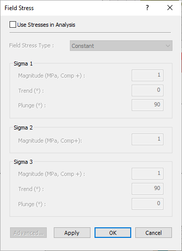
- To enable Field Stress, select the Use Stresses in Analysis checkbox.
- Set Field Stress Type = Constant .
This assumes that the initial in-situ stress does not vary with depth or location. - Enter the following magnitudes and orientations for the major, intermediate, and minor principal far field stress:
- Sigma 1: Magnitude = 1, Trend = 0, Plunge = 90
- Sigma 2: Magnitude = 0.85 MPa
- Sigma 3: Magnitude = 0.75, Trend = 90, Plunge = 0
The Sigma 1 and Sigma 3 orientations must be orthogonal to each other (i.e., the direction vectors must differ by 90 degrees). The orientation of Sigma 2 is automatically determined to be orthogonal to both Sigma 1 and Sigma 3.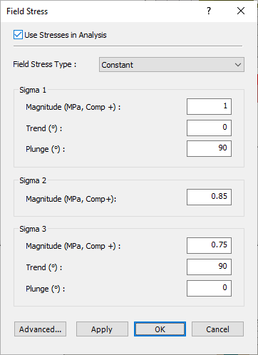
- Select OK.
3.1 FACTOR OF SAFETY WITH FIELD STRESS
Now observe the wedge Factors of Safety displayed in the Wedge Info panel. The following table summarizes the values before and after applying the Field Stress.
Wedge | Factor of Safety (No Field Stress) | Factor of Safety (With Field Stress) |
Lower Right Wedge | 0.210 | 0.729 |
Lower Left Wedge | 0.964 | 0.964 |
Roof Wedge | 0 | 1.165 |
Floor Wedge | stable | stable |
- Lower Right Wedge and Roof Wedge - The “clamping effect” of the Field Stress has significantly increased the Factor of Safety for the Lower Right Wedge (0.210 to 0.729) and for the Roof Wedge (0 to 1.165).
- Lower Left Wedge - For the Lower Left Wedge, the application of Field Stress did not change the reported Factor of Safety (0.964). In this case, the inclusion of Field Stress in the stability calculations actually results in a LOWER Factor of Safety for the wedge. When this occurs, the Factor of Safety that is reported is the original Factor of Safety, without Field Stress.
UnWedge always compares the stressed and unstressed values of Factor of Safety, and by default, reports the HIGHER of the two values. The logic behind this reasoning is as follows:
- If the actual stress distribution in the rock mass has a tendency to “push” the wedge into the excavation, then in effect, the wedge reverts to an unstressed state. The Factor of Safety then reverts to the original Factor of Safety, due to the self-weight of the wedge.
- Notice that the Lower Left Wedge is a relatively “flat” wedge. The geometry of this wedge is such that the Field Stress has a greater tendency to dislodge the wedge, rather than clamp the wedge in place.
3.2 VIEWING STRESS CONTOURS
When you are using the Field Stress option in UnWedge, the actual stresses computed on the wedge planes should be visible. If they are not, they can be turned on as follows:
- Right-click directly on any Perimeter Wedge in the 3D Wedge View.
- In the popup menu, you will see a Field Stress Visualization sub-menu.
- From this sub-menu you can choose to view contours of:
- Normal Stress
- Shear Stress
- Sigma 1
- Sigma 3
- Sigma X
- Sigma Y
- Tau XY
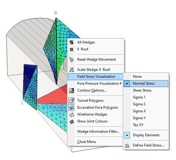
Field Stress Visualization Select - Select a data type from the list (e.g. Normal Stress), and the joint planes of all wedges will immediately display contours of the selected data type. A Field Stress Legend will also be displayed, so you can determine the values of the contours, as shown in the following figure.
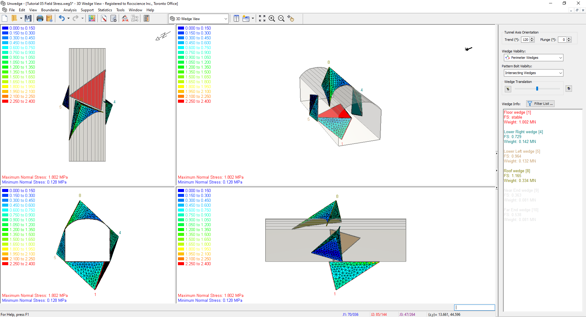
3D Wedge Model View
- Display Elements: If you see a mesh of triangular elements displayed on the wedge faces, the nodes of the mesh are the locations at which the stress is calculated on each wedge face. The stress contours are generated from these values. To show (or hide) the mesh, right-click on any wedge, and from the Field Stress Visualization sub-menu in the right-click menu, toggle the Display Elements option on (or off).
- Data Tips: When stress contours are displayed on the wedge planes, if you hover the mouse over any contoured wedge plane, a popup data tip will display the value of the stress at that location.
Notice that the value of stress displayed in the data tip corresponds to the stress contour values displayed in the Legend. Experiment with viewing different stress contours (e.g. Shear Stress).
3.3 ADVANCED FIELD STRESS OPTIONS
The boundary element stress analysis in UnWedge is not a “black box” – advanced users who wish to configure the settings of the analysis can do so with the Advanced Settings For Stresses dialog. To access this dialog:
- Select the Field Stress option from the Analysis menu or the toolbar.
- Select the Advanced button in the Field Stress dialog.
- You will see the following dialog, which allows you to configure the rock mass elastic parameters, boundary element discretization, solver type and other parameters related to the stress analysis and display of results.
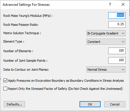
Before you close the dialog:
- Select the checkbox at the bottom of the dialog – Report Only the Stressed Factor of Safety.
- Select OK in the Advanced Settings For Stresses dialog.
- Select OK in the Field Stress dialog.
- Now, look at the wedge Factor of Safety displayed in the Sidebar. In particular, look at the Factor of Safety for the Lower Left Wedge and the Floor Wedge (these are highlighted in the following table).
Wedge | Factor of Safety (No Field Stress) | Factor of Safety (With Field Stress) |
Lower Right Wedge | 0.210 | 0.729 |
Lower Left Wedge | 0.964 | 0.746 |
Roof Wedge | 0 | 1.165 |
Floor Wedge | stable | 1.337 |
Notes:
- The Factor of Safety (with Field Stress) for the Lower Left Wedge is now LESS THAN the Factor of Safety without field stress.
- The Factor of Safety (with Field Stress) for the Floor Wedge is now a finite value, compared to the Stable result (without Field Stress).
As discussed earlier in this tutorial, by default UnWedge does NOT report Factor of Safety values (with Field Stress) when the values are LESS THAN the Factor of Safety (without Field Stress). The reasons for this have already been discussed. However, if you do wish to see the Factor of Safety (with Field Stress), regardless of the value, then you can select the checkbox in the Advanced Settings For Stresses dialog, as we have shown. These values are provided for academic interest, but it is not recommended that they be used for any design purposes.
3.4 SPEED OF CALCULATIONS WHEN USING FIELD STRESS
If you use the Field Stress option, this can noticeably affect the speed of the UnWedge calculations. This is because the boundary element stress analysis must be carried out first, before the limit equilibrium calculations. If the tunnel axis orientation is changed, the stress analysis must be re-computed. If joint orientations are changed, the stresses must be recomputed on each wedge face.
You may not notice any difference in speed for a simple analysis of a single tunnel orientation. However, if you are using the Tunnel Axis Plot option (for example), the plot generation may take some time if you are using Field Stress because the entire boundary element analysis has to be re-computed for each tunnel orientation.
3.5 END WEDGES AND FIELD STRESS
The stress analysis which is performed in conjunction with the Field Stress option in UnWedge is a plane strain analysis. It is assumed that the excavation is of infinite length. The stress distribution at the ends of the excavation is NOT computed. Therefore, the Field Stress option is only applicable for Perimeter Wedges in UnWedge and cannot be applied to the End Wedges. In order to apply Field Stress to End Wedges, a full 3D stress analysis of the excavation would be required. This is not within the current capabilities of UnWedge.
4.0 Conclusion
The Field Stress option in UnWedge is an interesting analytical tool which allows you to see the potential effects of including the actual rock mass stress in the wedge stability calculations.
However, the Field Stress option should be used with caution, and engineering judgment must be used when interpreting the results. If long-term behaviour is being considered, then the inclusion of Field Stress is NOT recommended, so the analysis and design of support are conservative.
This concludes the tutorial. You are now ready for the next tutorial, Tutorial 06 - Intersecting Tunnels in UnWedge.