10 - Ground Surface
1.0 Introduction
This tutorial will demonstrate the Add Ground Surface function in UnWedge. A ground surface can either be drawn within UnWedge or it can be imported as a DXF file. We will look at both options.
Topics Covered in this Tutorial:
- Adding a Ground Surface
- Importing a DXF Ground Surface
- Moving a Ground Surface
Finished Product:
The finished tutorial can be found in the Tutorial 10 Adding a Ground Surface.weg5 file located in the Examples > Tutorials folder in your UnWedge installation folder.
2.0 Model
- If you have not already done so, run the UnWedge program by double-clicking on the UnWedge icon in your installation folder. Or from the Start Menu, select Programs > Rocscience > UnWedge. If the UnWedge application window is not already maximized, maximize it now so that the full screen is available for viewing the model.
- For this tutorial, read in the file Tutorial 02 Scaling Wedges_initial.weg5, which you should find in the Examples > Tutorials folder in your UnWedge installation folder and open.
2.1 PROJECT SETTINGS
- Select Project Settings
 from the toolbar or the Analysis menu.
 - Ensure the Units = Metric, stress as MPa.
- Change the Analysis Type = Probabilistic.
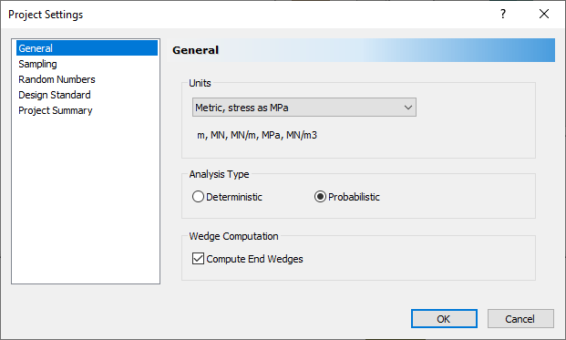
- Select OK.
2.2 INPUT DATA
- Select Input Data
 from the toolbar or the Analysis menu.
 - Select the Joint Orientations tab.
- Change Joint 1 Dip = 80, and Joint 3 Dip = 85.
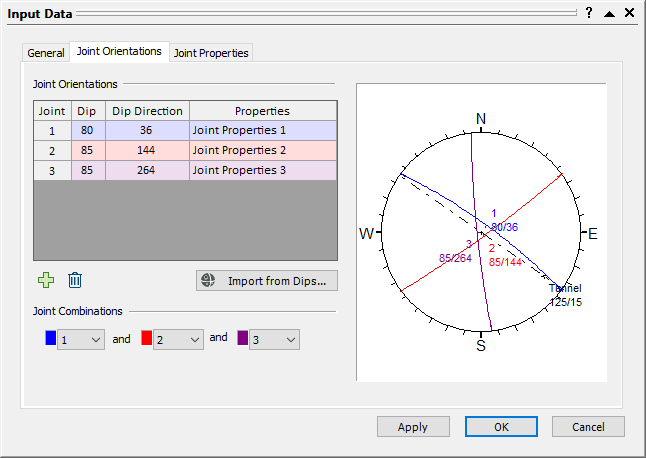
- Select OK.
3.0 Adding a Ground Surface
- Switch to the Perimeter Support Designer
 view.
view. - Select Boundaries > Add Ground Surface
 .
. - Enter the following coordinates in the prompt line at the bottom right of the screen. Press ENTER at the end of each line to enter each coordinate pair:
- Enter vertex [t=table,a=arc,esc=cancel]: 25, 65
- Enter vertex [t=table,a=arc,esc=cancel]: 70, 65
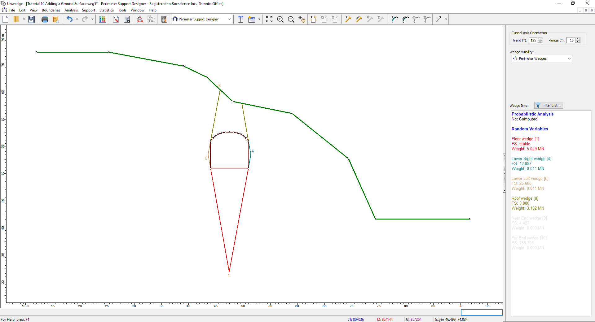
Your screen should look as follows:
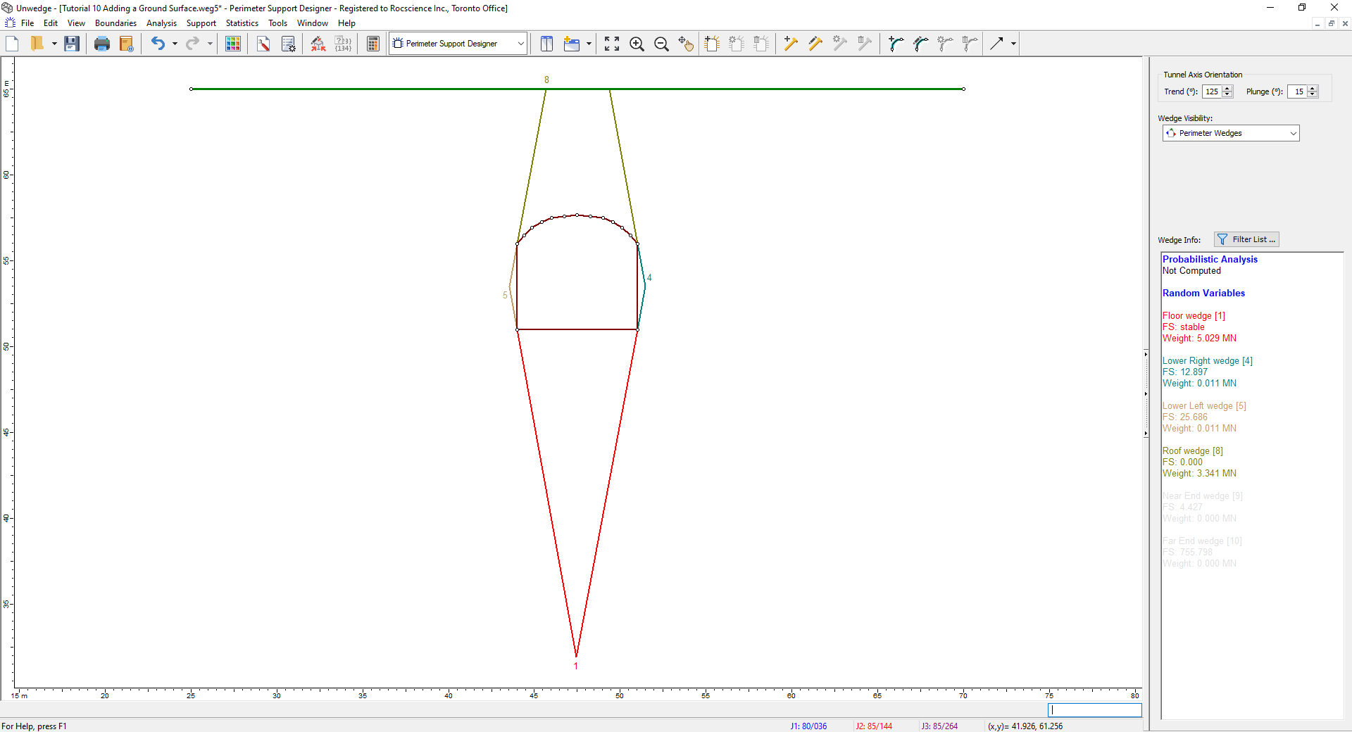
We can now view the Deterministic results of this geometry.
 to see how a ground surface appears in the 3D Wedge View.
Below, you can see a side-by-side comparison of the resulting changes.
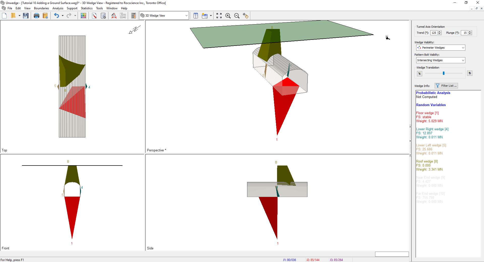
As expected, the Weight and Apex Height of the Roof wedge have decreased. Additionally, the Required Support Pressure has decreased, due to the lower self-weight of the wedge. All other values have remained the same.
4.0 Importing a Ground Surface (DXF)
We will now import a Ground Surface from a DXF file.
- Switch back to the Perimeter Support Designer view.
- Right-click on the Ground Surface in the model and select Delete Ground Surface
 from the popup menu.
 - Select File > Import > Import DXF
 .
. - Open Tutorial 10 Ground Surface.dxf.
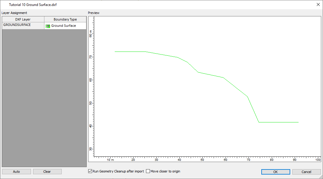
- Select OK.
The ground surface should appear on your screen.
- Right-click on the Ground Surface, and select Move Ground Surface
 .
. - Click on the left-most vertex of the Ground Surface.
- Enter the following coordinates in the prompt line at the bottom right of the screen: 7, 71.
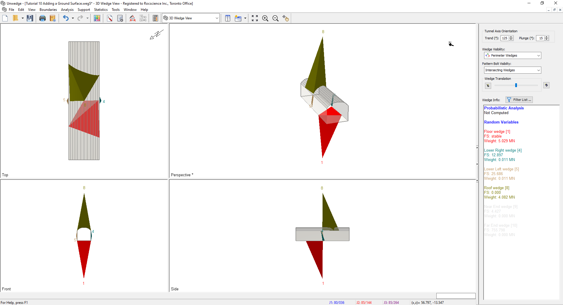
- Switch to the 3D Wedge View .
The 3D Wedge View should look as follows:

This concludes the tutorial. You are now ready for the next tutorial, Tutorial 11 - Advanced Joint Combination Analysis in UnWedge.