1 - Quick Start
This tutorial is a simple introductory tutorial that helps you become familiar with the basic modelling and data interpretation features of UnWedge.
A key tool for geotechnical engineers that work with tunnels, underground excavations, and caverns, UnWedge is used to determine the stability of rock wedges formed by the intersection of structural discontinuities. UnWedge the calculates Factor of Safety and can determine support requirements for projects.
Topics Covered:
- Project Settings
- Defining the Opening Section
- Tunnel Properties
- Joint Orientations
- Joint Properties
- 3D Wedge View
- Viewing and Display Options
- Wedge Analysis Information
- Data Tips
- Info Viewer
- Multi-Perspective View
- End Wedges
Finished Product:
The finished product of this tutorial can be found in the Tutorial 01 Quick Start.weg5 file. located in the Examples > Tutorials folder in your UnWedge installation folder.
1.0 Introduction
There are several important assumptions and limitations which must be considered when using UnWedge:
- UnWedge should be used to analyze wedge failure around excavations constructed in hard rock, where discontinuities are persistent, and where stress-induced failure does not occur. It is assumed that displacements take place at the discontinuities and that the wedges move as rigid bodies with no internal deformation or cracking.
- The wedges are tetrahedral in nature and defined by three intersecting discontinuities. A maximum of three structural planes can be analyzed at one time. If more than three major planes are identified for the analysis of the structural data, then all combinations of these planes should be considered.
- All of the discontinuity surfaces are assumed to be perfectly planar.
- Discontinuity surfaces are assumed to be persistent and to extend through the volume of interest, therefore the discontinuities defining the wedge do not terminate within the region where the wedges are formed. The implication is that no new cracking is required in the analysis of wedge movement.
- The discontinuities are considered to be ubiquitous: in other words, they can occur at any location in the rock mass.
- The underground excavation is assumed to have a constant cross-section along its axis.
- The default analysis is based upon the assumption that the wedges are subjected to gravitational loading only, due to the wedge weight (i.e., the stress field in the rock mass surrounding the excavation is not taken into account). While this assumption leads to some inaccuracy in the analysis, the error is generally conservative, leading to a lower Factor of Safety. However, you may include the effect of in-situ stress on the wedges with the Field Stress option.
- UnWedge always initially calculates the maximum sized wedges which can form around the excavation. To scale down the size of the wedges according to actual field observations (e.g., observed joint trace lengths), use the Scale Wedges option.
2.0 Creating a New File
- If you have not already done so, run the UnWedge program by double-clicking the UnWedge icon in your installation folder or by selecting Programs > Rocscience > UnWedge > UnWedge in the Windows Start menu.
When the program starts, a default model is automatically created. If you do NOT see a model on your screen:
- Select: File > New

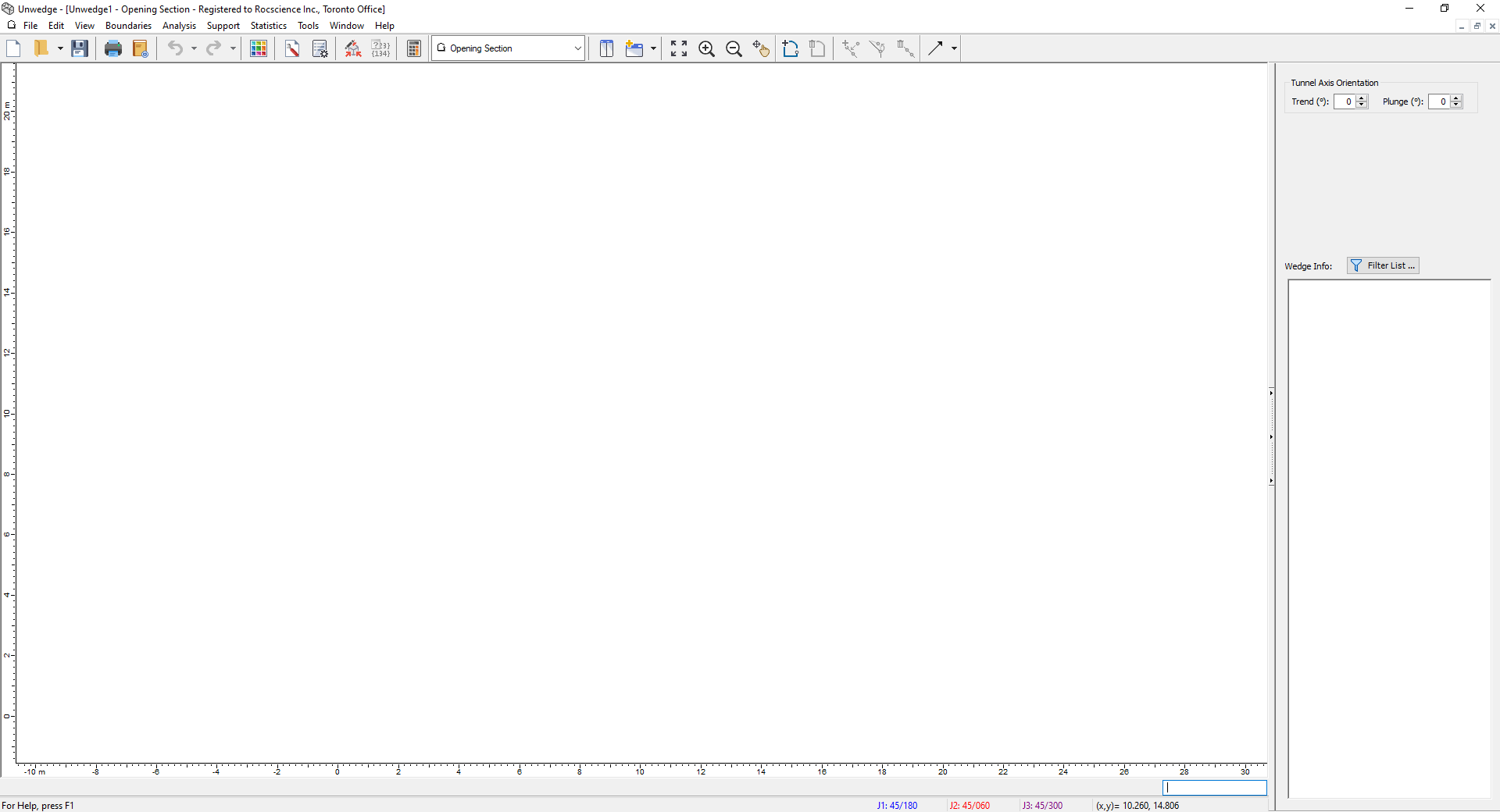
If the UnWedge application window is not already maximized, maximize it now so that the full screen is available for viewing the model.
3.0 Project Settings and Model Geometry
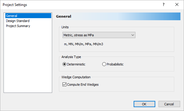
3.1 PROJECT SETTINGS
The Project Settings dialog allows you to configure the main analysis parameters for your model, such as Analysis Type, Units, and Design Standard options that will be explored in later tutorials. To open the dialog:
- Select: Analysis > Project Settings

There are two main analysis types in UnWedge: Deterministic and Probabilistic. The default choice for new files is Deterministic.
- Deterministic Analysis: Assumes that all input parameters are exactly known. UnWedge computes the Factor of Safety for each wedge. This tutorial demonstrates a Deterministic Analysis.
- Probabilistic Analysis: Statistical input data can be entered to account for uncertainty in joint orientation and strength values. The result is a distribution of Factors of Safety, from which a Probability of Failure is calculated. Probabilistic Analysis is demonstrated in Tutorial 07 - Probabilistic Analysis in UnWedge.
- Ensure Units = Metric, stress as MPa.
- Ensure Analysis Type = Deterministic.
- Ensure that the Compute End Wedges checkbox is selected.
- Select OK to close the dialog.
3.2 MODEL GEOMETRY
We will start by creating the two-dimensional cross-section of the excavation we want to analyze. The cross-section can either be imported as a DXF file or defined within the program using the Add Opening Section option. For this tutorial, we will use the Add Opening Section option.
- Make sure Opening Section
 is selected in the View dropdown on the toolbar.
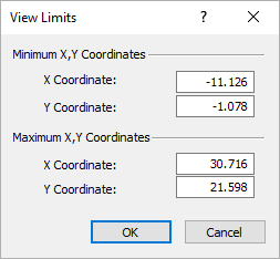
 - Select View > View Limits
 .
.
The View Limits dialog appears.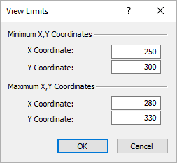
- Enter 250, 300 for the Minimum X, Y Coordinates and 280, 330 for the Maximum X, Y Coordinates.
- Select OK.
- Select Add Opening Section
 on the toolbar or the Boundaries menu.
 Enter the following coordinate pairs in the prompt line at the bottom right of the screen.
The X and Y coordinates can be separated by a space or a comma. Press ENTER at the end of each pair/line.X
Y
264.5
303
273
303
273
306
277.5
306
277.5
317

- After entering the above 5 coordinate pairs, type a and hit ENTER in the prompt line to enter an arc.

An Arc Options dialog appears.
- Under Arc Definition Method, select 3 points on arc.
- Under Arc to Polyline Conversion Method, select Number of segments = 12.
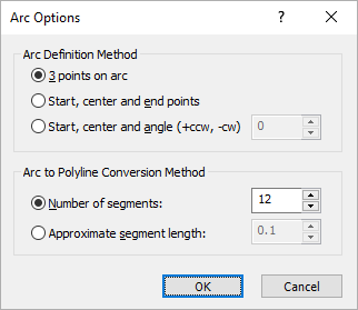
- Select OK.
- In the prompt, Enter second arc point = 271, 320 and hit ENTER.

- Enter third arc point = 264.5, 317 and hit ENTER.

- In the prompt, type c and hit ENTER to close the boundary automatically (i.e., the last vertex is joined to the first vertex).

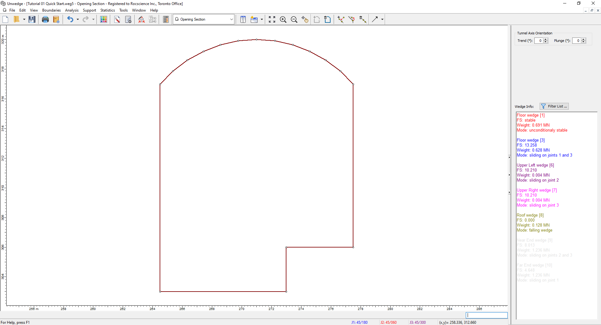
If everything is entered correctly, the excavation boundary will look as in the figure below:
- If the Opening Section boundary did not automatically zoom to the center of the view, select Zoom All
 on the toolbar or press F2.
4. Input Data
Now we'll define Tunnel Properties, Joint Orientations, and Joint Properties using the Input Data dialog. To open the dialog:
- Select: Analysis > Input Data

4.1 TUNNEL PROPERTIES
Let's start by defining Tunnel Properties:
- Select the General tab in the Input Data dialog.

Input Data Dialog - Under Tunnel Axis Orientation, set Trend = 45 and Plunge = 0.
- Make sure the Rock Unit Weight is 0.027 MN/m 3.
- Make sure the Seismic Force checkbox is unchecked.
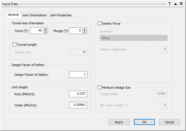
Input Data Dialog
4.2 JOINT ORIENTATIONS
Now we'll define Joint Orientations:
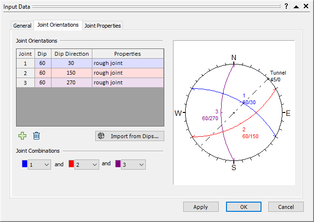
- Select the Joint Orientations tab.
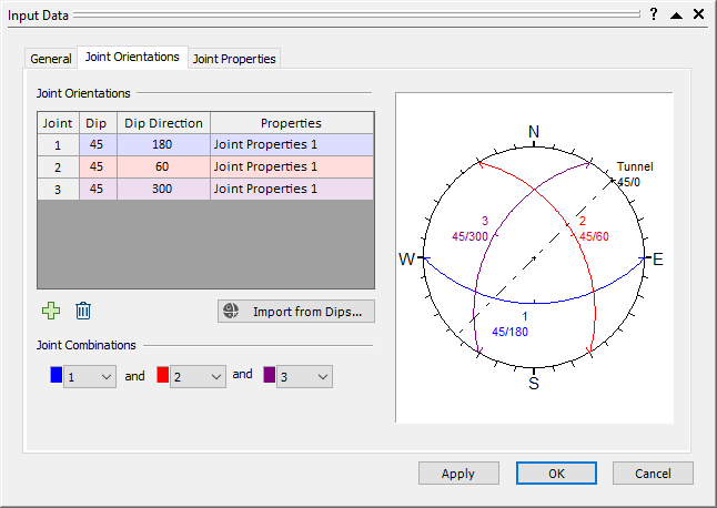
Input Data Dialog - Enter the following Dip / Dip Direction for the 3 joints, as shown:
Joint 1 = 60/30
Joint 2 = 60/150
Joint 3 = 60/270.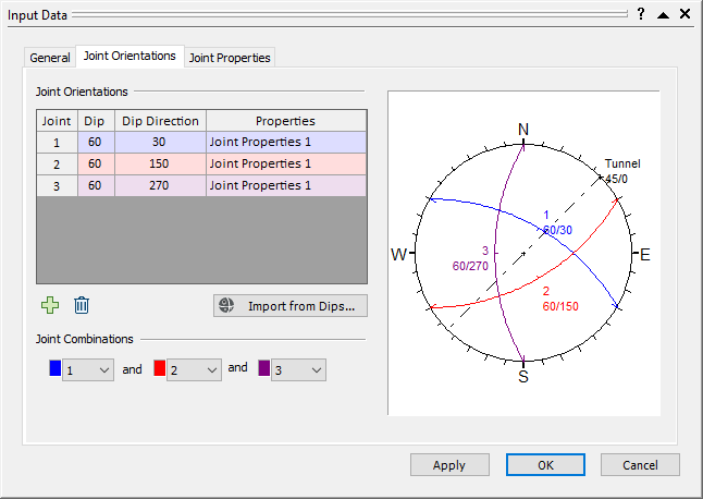
Input Data Dialog
Notes:
- Notice the stereonet at the right of the Input Data dialog, which displays the great circles corresponding to the current joint orientation data.
- Also, note that the Tunnel Axis Orientation (dotted line) is displayed on the stereonet. The stereonet can also be viewed by selecting Stereonet
 in the View drop-down on the toolbar.
4.3 JOINT PROPERTIES
Finally, we'll define the Joint Properties. We will define two joint property types – smooth and rough.
- Select the Joint Properties tab.
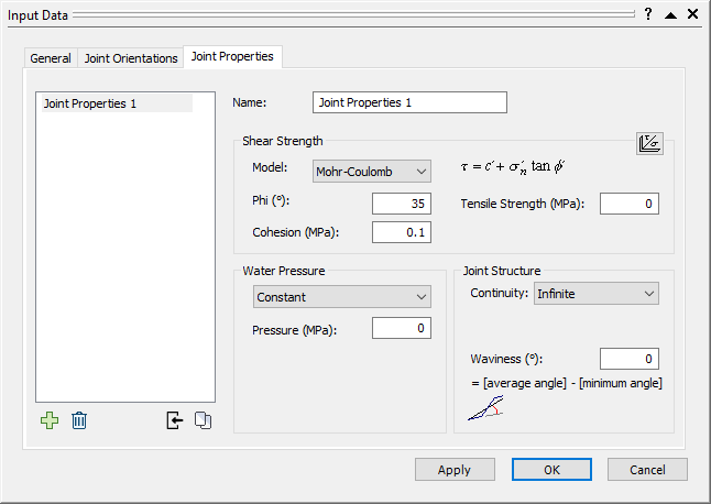
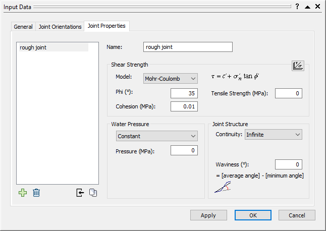
Input Data Dialog - Set the Name of the default joint type to rough joint .
- Under Shear Strength:
- Set Model = Mohr-Coulomb.
- Set Phi = 35 degrees.
- Set Cohesion = 0.01 MPa.
- Leave all other rough joint properties at the default settings.
Input Data Dialog
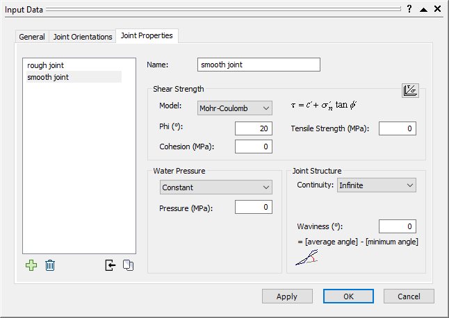
- To create a new joint property type, select the Add
 button below the Joint Types list and name it smooth joint.
 - Under Shear Strength:
- Set Model = Mohr-Coulomb.
- Set Phi = 20 degrees.
- Set Cohesion = 0 MPa.
- Leave all other smooth joint properties at the default settings.
Input Data Dialog
4.4 ASSIGN JOINT TYPES TO JOINTS
Now we need to assign the joint property types to the joints.
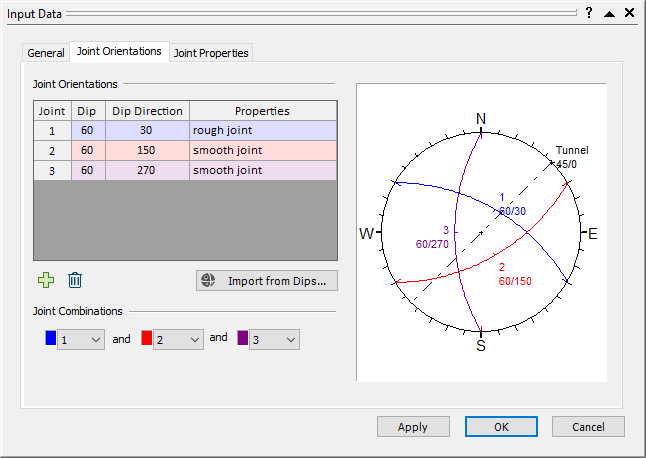
- Return to the Joint Orientations tab.
Input Data Dialog
Notice that all the joints are automatically assigned the first (rough joint) property under the Properties column. - Retain the rough joint property for Joint 1.
- Assign the smooth joint property to Joint 2 and Joint 3 by selecting it in the Properties dropdown.
Input Data Dialog - Select OK to save all of the information we have entered.
We are now finished entering all the Input Data for this tutorial and are ready to view the results of the analysis.
5.0 Analysis Results
When conducting a Deterministic Analysis, UnWedge automatically computes the wedge stability analysis whenever data is entered or modified, so it is not necessary to select the Compute option. As long as the Opening Section has been defined, results can be immediately viewed at any time.
When viewing results, the 3D Wedge View is usually the first screen you will want to look at. To switch to the 3D Wedge View:
- Select: View > Select View > 3D Wedge View

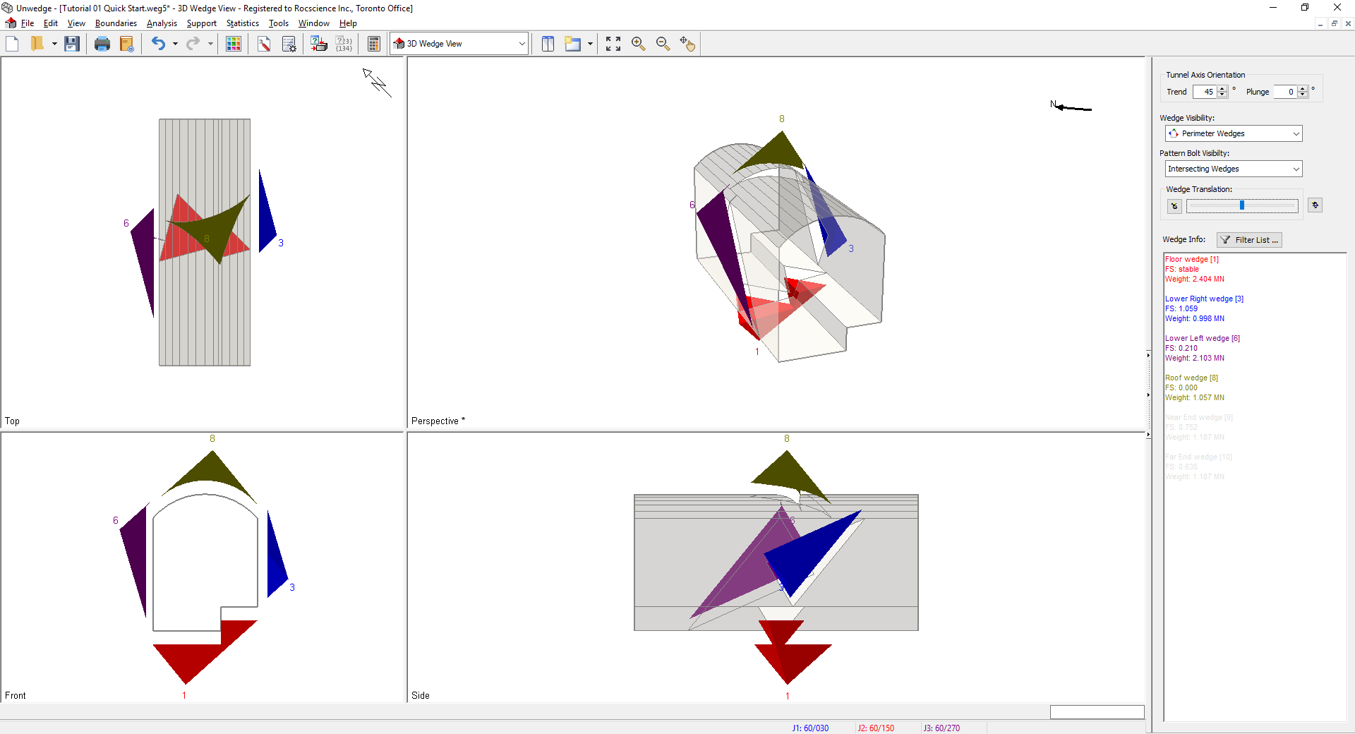
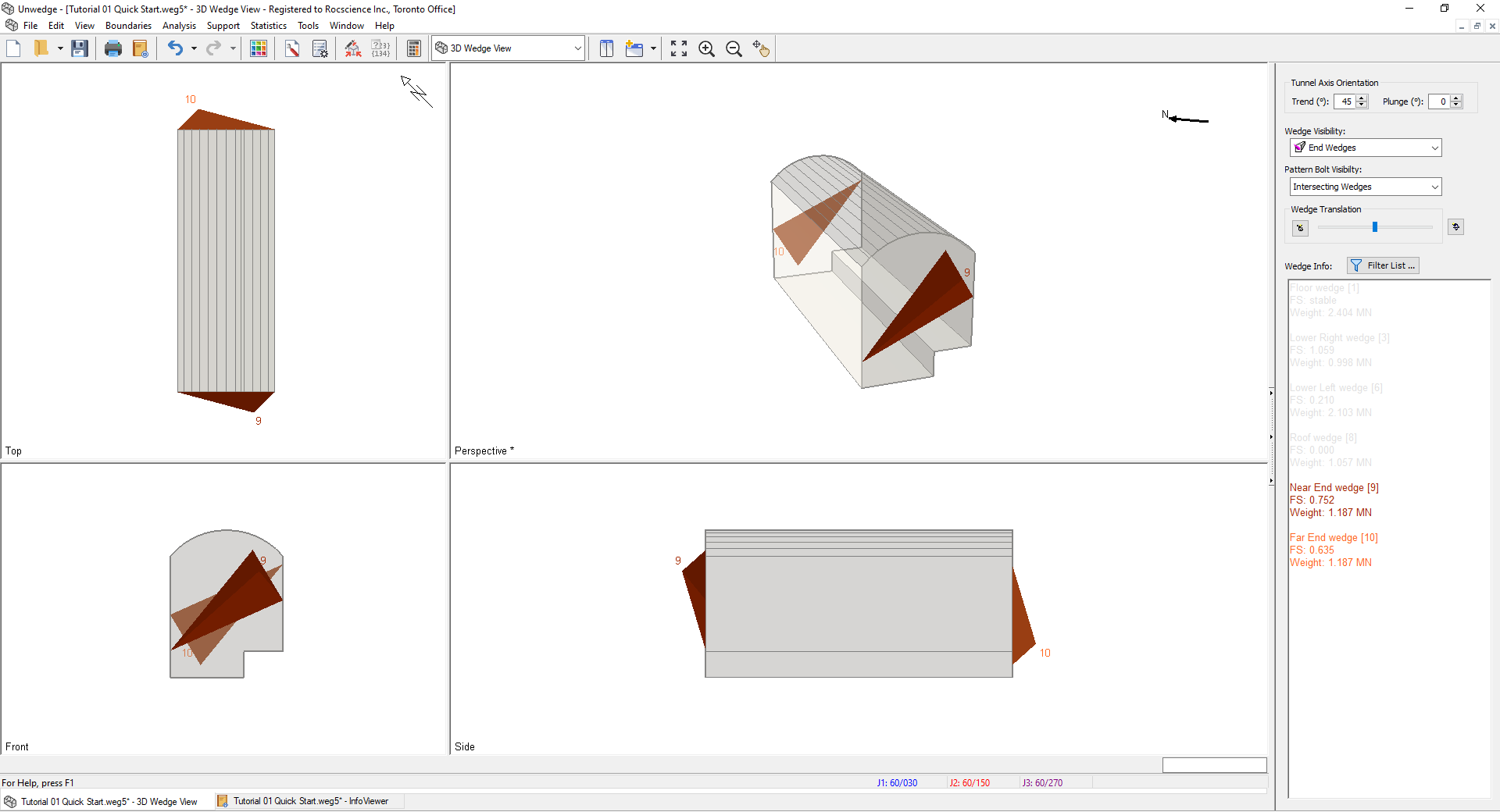
You should see the following screen:
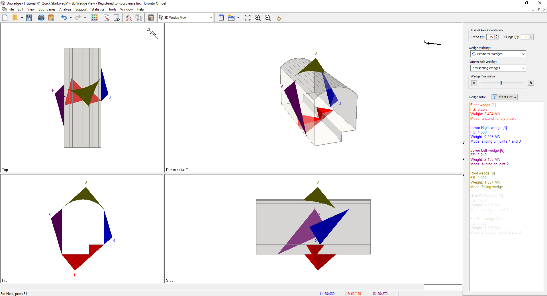
As you can see, the 3D Wedge View presents 4 views of the model:
- A three-dimensional Perspective view
- Three orthogonal views of the excavation: Top, Front, and Side.
By default, all possible Perimeter Wedges are displayed in the 3D Wedge View.
6. Viewing Options
We will now discuss some of the viewing options and shortcuts for the 3D Wedge View.
6.1 ROTATING THE MODEL
You can interactively rotate the UnWedge model in the Perspective view using the mouse to view it at any angle.
- Press and hold the left mouse button anywhere in the Perspective view.
Notice that the cursor changes to a “circular arrow” symbol to indicate that you may rotate the model.
 - Keep the left mouse button pressed, and move the cursor around.
The model is rotated according to the direction of movement of the cursor. - To exit the rotation mode, release the left mouse button.
The cursor reverts to the normal arrow cursor.
TIP: To reset the rotation to the default viewing angle, select Reset Rotation  in the Sidebar or the right-click menu.
6.2 MOVING THE WEDGES
The wedges in the 3D Wedge View can be interactively moved from their default positions around the excavation:
- Individual wedges can be moved, or all wedges can be translated simultaneously.
- The wedges can be moved into or away from the excavation.
- The direction of movement is always the sliding direction for each wedge.
There are several different ways in which the user can interactively move the wedges:
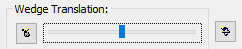
- Use the mouse to click or drag the Wedge Translation slider control in the Sidebar.
- Rotate the mouse wheel while holding down the SHIFT or CTRL keys on the keyboard ( SHIFT key for larger increments; CTRL key for smaller increments)
- Individual wedges can be moved by clicking and dragging them with the left mouse button (place the cursor over the desired wedge, and when the cursor changes to an arrow
 symbol, click and drag the mouse).
TIP: To restore the wedges to their default position, select the Reset Wedge Movement  option in the Sidebar or the right-click menu, or double-click the middle mouse button in any view.
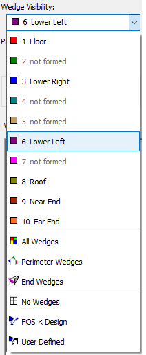
6.3 WEDGE VISIBILITY
The Wedge Visibility option in the Sidebar allows you to select which wedges are visible in the 3D Wedge View. You can view:
- All Wedges
- Perimeter Wedges only
- End Wedges only
- Any individual wedge (i.e., 1 Floor, 3 Lower Right)
- Wedges with Factor of Safety less than the design value (i.e., FOS < Design)
- Any User Defined selection of wedges
EXAMPLES:
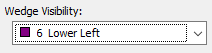
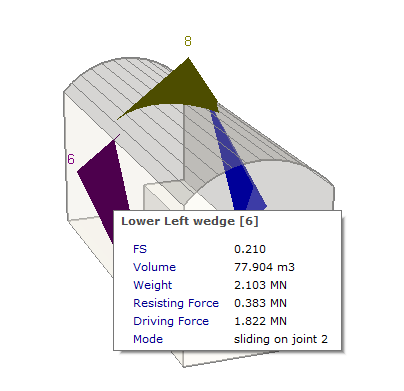
- Click on the Wedge Visibility drop-list in the sidebar and select the 6 Lower Left wedge. Your screen should appear as below.
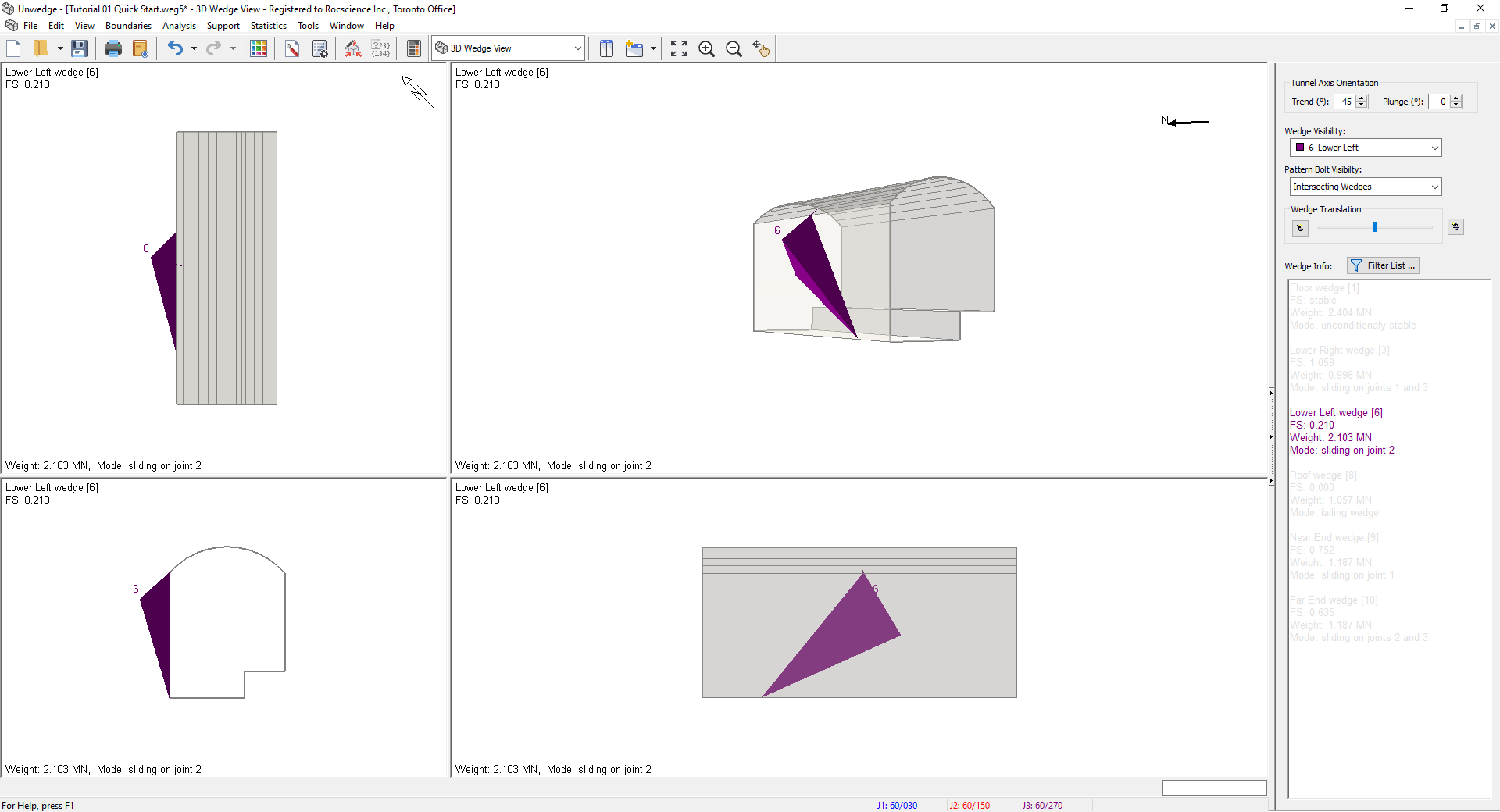
3D Wedge View Model - Select the Wedge Visibility = All Wedges option and you will see all possible wedges, including Perimeter Wedges and End Wedges. Select the Wedge Visibility = Perimeter Wedges option to display only the Perimeter Wedges once again.
6.4 RESIZING THE VIEWS
You can change the relative size of the panes or sub-views (Top/Front/Side/Perspective), or maximize any view within the 3D Wedge View.
- To maximize the size of any pane, double-click the left mouse button in the pane. Double-clicking again in the maximized view will restore the default display of all four panes.
- You can also re-size the four-pane display by clicking and dragging on the vertical or horizontal dividers between the panes.
- If you have re-sized the panes and you want to quickly restore the default display, double-quick in any pane to maximize the view, then double-click again to restore the default display.
6.5 ZOOM AND PAN
Zooming and panning are available on all views of the model (e.g., 2D views such as the Opening Section View, and 3D views such as the 3D Wedge View). The zoom and pan options are:
- Zoom All : Reset the model to its default size and location in the view
- Zoom In
 : Zoom in to 90 % of the original area
 - Zoom Out
 : Zoom out to 111% of the original area
 - Pan
 : Translate the model left, right, up or down within the view
The Zoom and Pan options are available on the toolbar, the View > Zoom menu, and through various keyboard and mouse shortcuts. Shortcuts include:
- Rotate the mouse wheel forward or backward to zoom in or out.
- The function keys F2, F4, and F5 are shortcuts to Zoom All, Zoom Out and Zoom In respectively.
- If you hold down the SHIFT key while using any zoom option, all four panes of the 3D Wedge View will be zoomed simultaneously.
- A shortcut to Pan is to click and hold the middle mouse button (mouse wheel) and drag to pan the model within the view.
6.6 TOOLS MENU
The Tools menu can be used on any of the two-dimensional views (Opening Section, Perimeter Support Designer View, End Support Designer View) to add annotations such as dimensions, arrows, notes, and others. It will be left as an exercise to the user to try the different tools provided.
7.0 More Results Viewing Options
7.1 WEDGE INFORMATION
Detailed analysis results (e.g., Factor of Safety, wedge weight, wedge volume, joint trace lengths, sliding direction, etc.) are available for all wedges computed by UnWedge. The wedge information is available in several different locations within the program:
- Wedge Info panel in the Sidebar
- Wedge Information Filter
- Popup Data Tips (hover the mouse over a wedge to see the wedge information for that wedge)
- Info Viewer
7.1.1 Wedge Info Panel
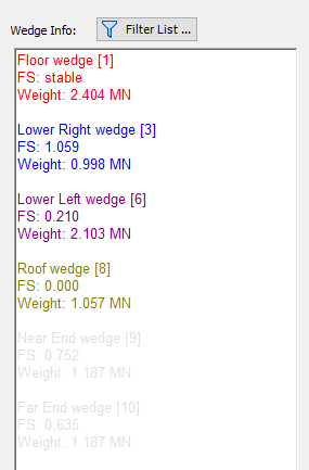
The Wedge Info panel in the Sidebar displays the wedge analysis results for all visible wedges.
- Wedges are identified by name and number. Also, the colour of the text in the Wedge Info panel corresponds to the colour of each wedge in the model.
- Information is displayed for visible wedges only (i.e., the wedges displayed according to the Wedge Visibility option).
Examine the Wedge Information for this model. Note that the Factor of Safety for most of the wedges is less than 1, indicating that support would be needed to stabilize the wedges. The addition of support will be covered in a subsequent tutorial.
7.1.2 Wedge Information Filter:
The information displayed in the Wedge Info panel can be customized with the Wedge Information Filter dialog:
- Select the Filter List
 button in the Sidebar.
 - Select the information to display in the Wedge Info panel by selecting the corresponding checkboxes.
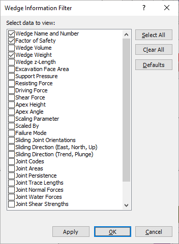
The Wedge Information Filter option also determines the wedge information displayed by Data Tips or the Info Viewer, as described in the next sections.
Note: If a filter is applied, the Filter List icon will display as  .
.
7.1.3 Data Tips
Data Tips are a very handy feature of UnWedge that allows you to graphically access information about input parameters and analysis results by hovering the mouse over the desired entities on the screen. This will display a popup box with information about the object. The following information can be displayed as Data Tips:
- Wedge Information for each wedge
- Joint Properties
- Support Properties (bolts, shotcrete, pressure)
- Coordinates of Opening Section vertices
For example, if you hover the mouse over any wedge, you will see the analysis information for that wedge.
Notes:
- The Data Tips option is usually ON by default. However, it can be set to Minimum or Off in the View > Data Tips menu. If you do not see any Data Tips, go to the menu and set it to Maximum.
- Another useful tip to remember is the following:
- If you right-click directly on any wedge and select the Show Joint Colours option from the popup menu, the joint colours will be displayed on each wedge plane.
- If you now hover the mouse over any wedge plane, the Joint Properties will be displayed, as shown below.
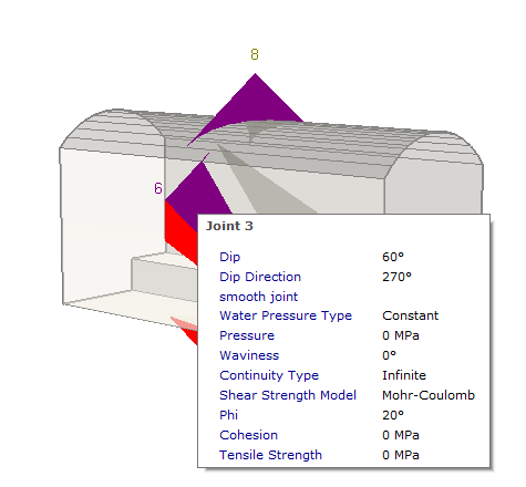
- Right-click again on any wedge and turn the Show Joint Colours option OFF. The Show Joint Colours option is also available in the General tab of the Display Options dialog. In the dialog, you can also customize the colours used to display the joints.
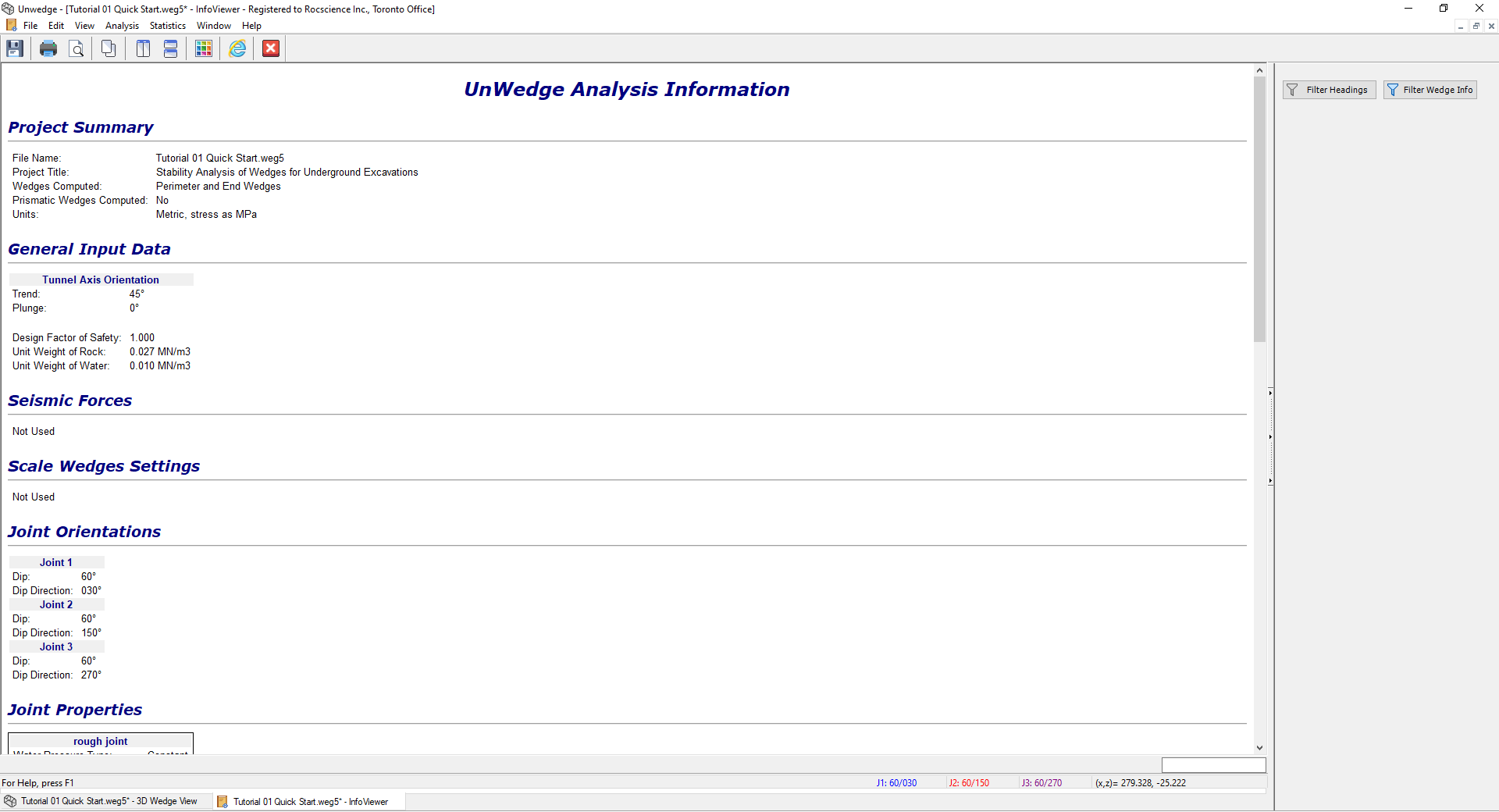
7.1.4 Info Viewer
The Info Viewer provides a comprehensive summary of model input data and analysis results in an easy-to-follow text listing. The information displayed in the Info Viewer can be filtered according to user preferences. It can also be saved by the user in a variety of ways including in reports.
To access the Info Viewer:
- Select: Analysis > Info Viewer

The Sidebar on the right provides options for filtering the information displayed, and right-clicking provides options for saving the information to a file. This is left as an optional exercise for the user to experiment with.
- Return to the 3D Wedge View by clicking on the 3D Wedge View tab on the bottom left of the screen.
7.2 END WEDGES
There are two main types of wedge determined by UnWedge:
- Perimeter Wedges: Wedges that can form around the perimeter of the excavation.
- End Wedges: Wedges that can form at either end of the excavation.
To display End Wedges in the 3D Wedge View:
- Select End Wedges in the Wedge Visibility dropdown in the Sidebar.
To display each End Wedge in its own Perspective pane:
- Select End Wedges
 from the View dropdown on the toolbar.
Notes:
- Depending on your joint and tunnel orientations, End Wedges may or may not exist.
- If the Opening Section axis has a vertical plunge, the End Wedges will be roof and floor wedges.
TIP: By default, UnWedge calculates End Wedges. If you are interested only in Perimeter Wedges, you can turn OFF the calculation of End Wedges in the Project Settings dialog by clearing the Compute End Wedges checkbox (see Section 3.1). In general, this should not be necessary. However, in some situations (e.g., if you are using the Tunnel Axis Plot option to optimize the tunnel orientation), the computation will be faster if you turn OFF the calculation of End Wedges.
7.3 MULTI-PERSPECTIVE VIEW
Another viewing option in UnWedge is the Multi-Perspective View. This view displays all possible wedges (including End Wedges), each in its own individual Perspective view.
To switch to the Multi-Perspective View:
- Select Multi-Perspective
 on the View dropdown on the toolbar or the View > Select View menu.
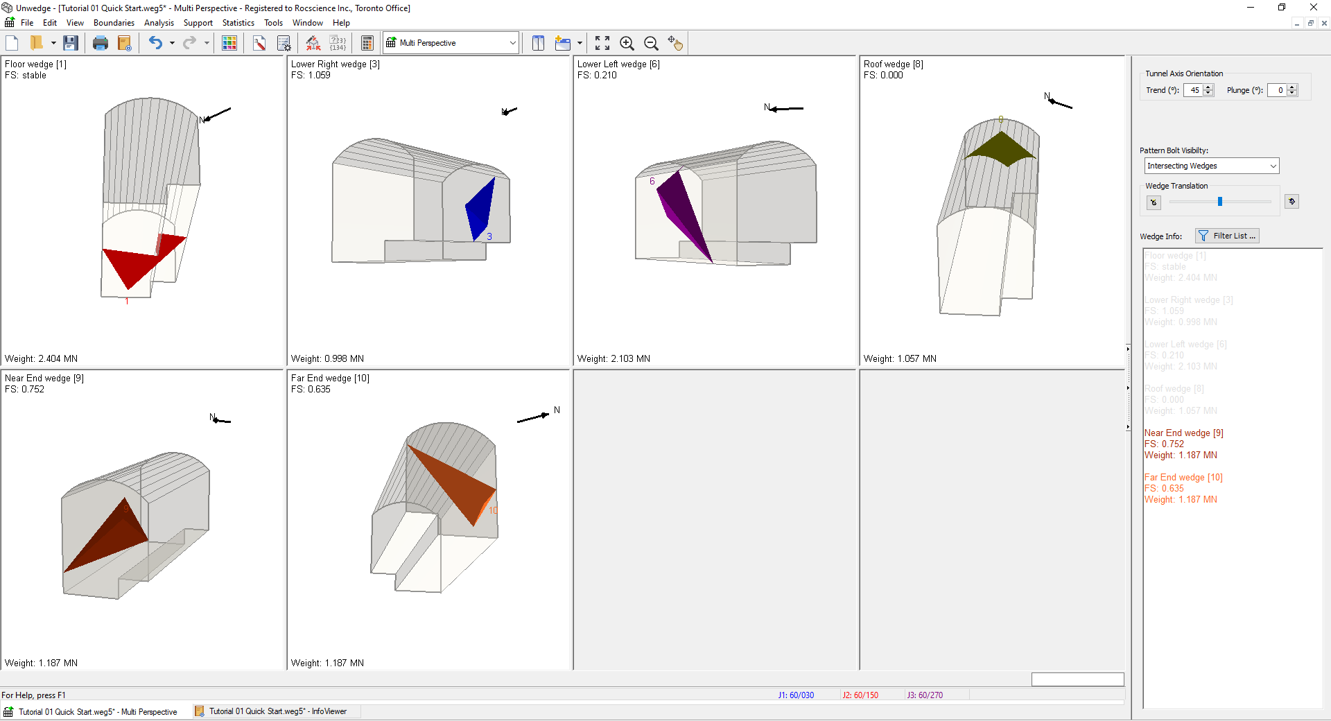
TIP: In the Multi-Perspective View, information for each wedge is displayed directly in the viewing pane for the wedge. The viewing properties of the view are very similar to the 3D Wedge View (e.g., double-click in any pane to maximize it).
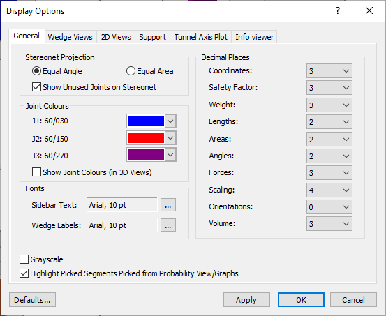
7.4 DISPLAY OPTIONS
Before we conclude this tutorial, we'll look at the Display Options dialog. The Display Options provide a great variety of options for customizing the appearance of the model. Each view in the program has different associated display options.
To open the Display Options dialog:
- Select: View > Display Options

It is recommended that you experiment with the Display Options dialog to become familiar with all of the different options.
This concludes the tutorial. You are now ready for the next tutorial, Tutorial 02 - Scaling Wedges in UnWedge.