3 - Perimeter Support
1.0 Introduction
This tutorial demonstrates how to add support to Perimeter Wedges using pattern bolts and shotcrete in order to increase the Factor of Safety of the wedges.
Topics Covered in this Tutorial:
- Perimeter Support Design View
- Wedge Apex Height
- Adding a Bolt Pattern
- Bolt Properties
- Editing a Bolt Pattern
- Bolt Data Tips
- Bolt Support Force Diagram
- Adding Shotcrete
- Editing Shotcrete
- Shotcrete Properties
Finished Product:
The finished product of this tutorial can be found in the Tutorial 03 Perimeter Support.weg5 file, located in the Examples > Tutorials folder in your UnWedge installation folder.
2.0 Model
- If you have not already done so, run the UnWedge program by double-clicking the UnWedge icon in your installation folder or by selecting Programs > Rocscience > UnWedge > UnWedge in the Windows Start menu. When the program starts, a default model is automatically created.
If the UnWedge application window is not already maximized, maximize it now so that the full screen is available for viewing the model.
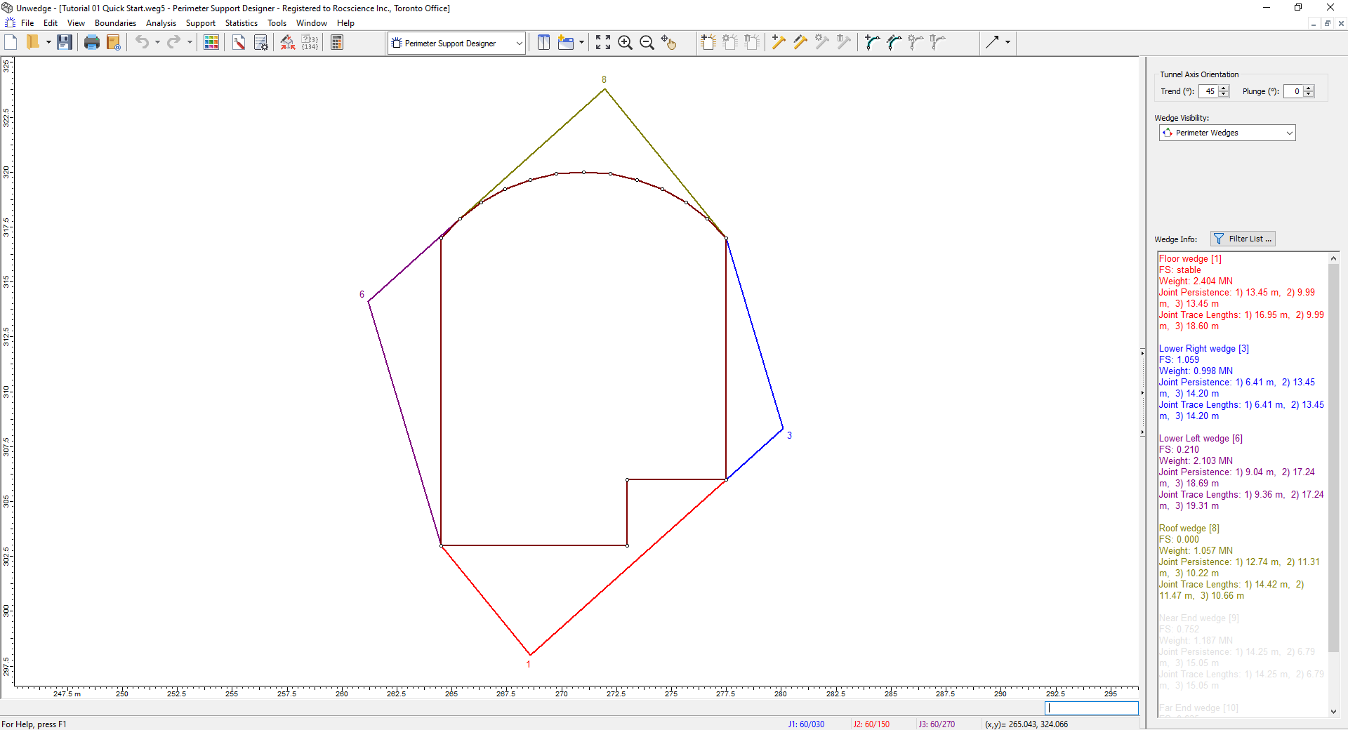
For this tutorial, we will start with the same model used for Tutorial 01 - UnWedge Quick Start, which represents an underground powerhouse cavern for a hydroelectric power generation project. Because we're adding support to Perimeter Wedges, we'll also open the Perimeter Support Designer View.
- Select
 File > Recent Folders > Tutorials Folder.
 - Open the Tutorial 01 Quick Start.weg5 file.
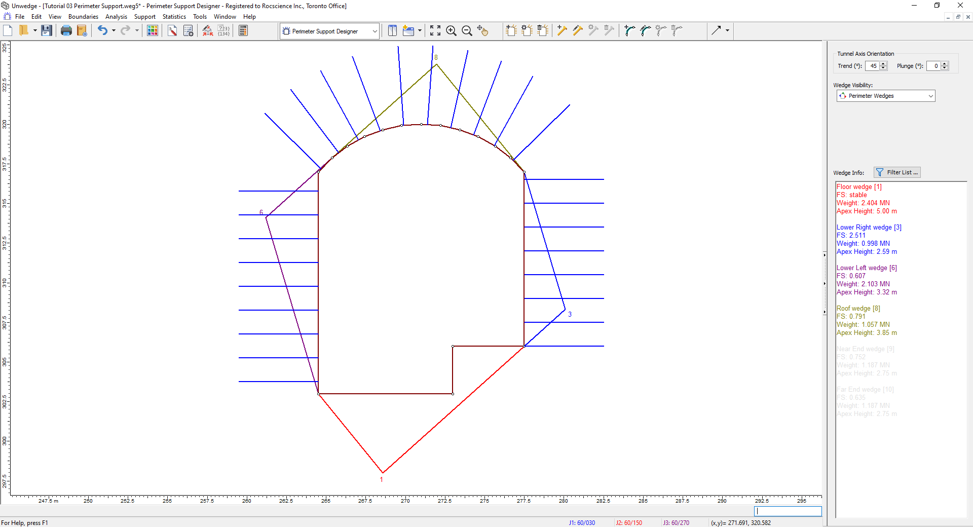
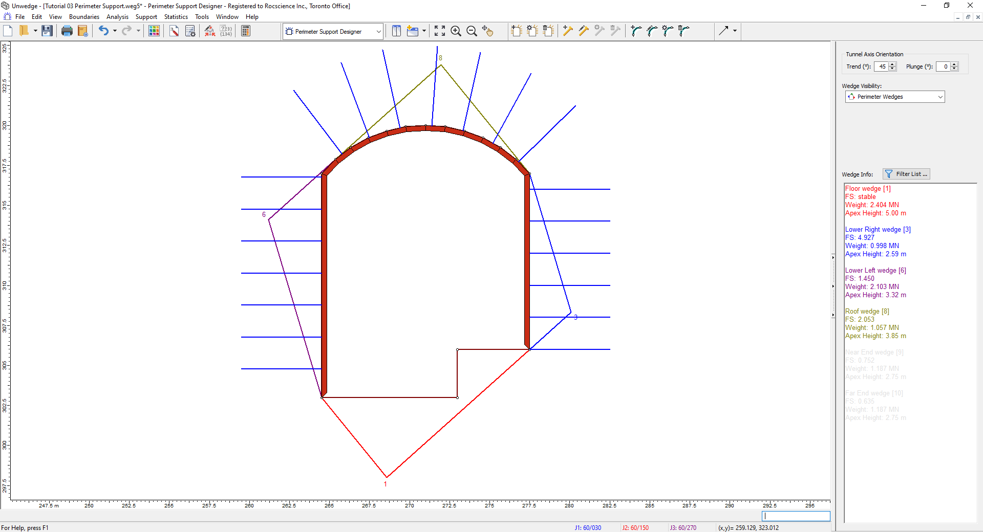
- Select Perimeter Support Designer from the View dropdown on the toolbar.
3.0 Perimeter Support: Bolt Pattern
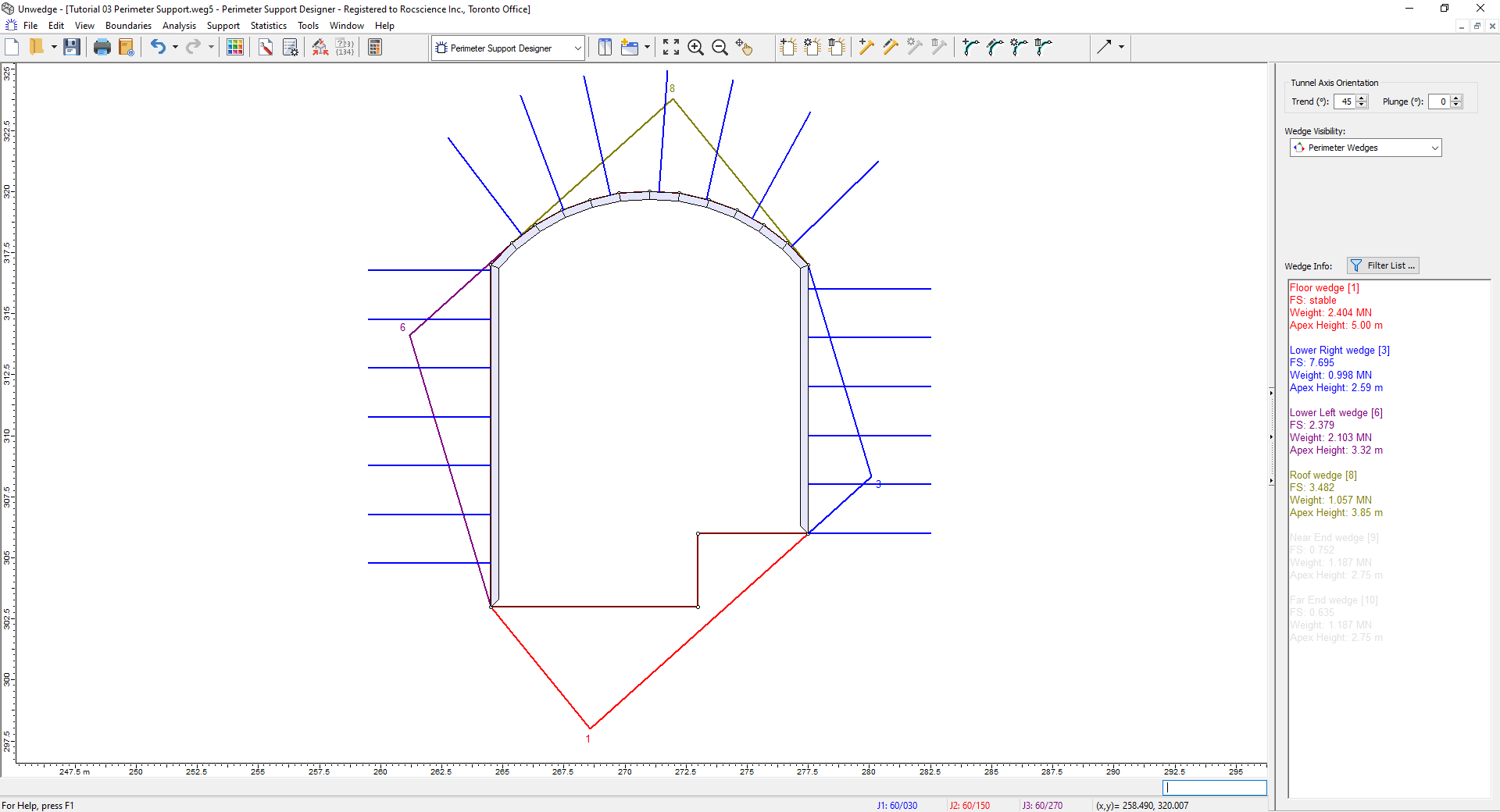
The Perimeter Support Designer View is a two-dimensional view that allows you to add or edit support (bolts, shotcrete, or pressure) on the perimeter of the excavation.
The view displays:
- The Opening Section boundary
- The Perimeter Wedges, in two dimensions, around the perimeter of the excavation
- The perimeter support that has been applied (bolts, shotcrete, pressure)
The two-dimensional display of the Perimeter Wedges allows you to easily determine the extent of pattern bolting, shotcrete, or pressure that must be applied in order to support the Perimeter Wedges.
3.1 WEDGE APEX HEIGHT
Before we add a Bolt Pattern, let’s display the wedge Apex Height so that we have an idea of the bolt length that will be required. The Apex Height is the shortest distance from the apex of a wedge to the excavation boundary, measured in the two-dimensional plane of the Opening Section.
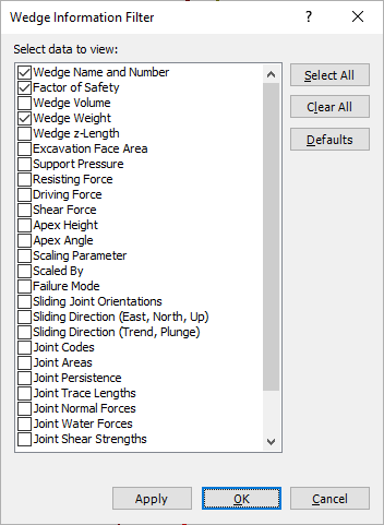
- Select the Filter List
 button in the Sidebar.
 - In the Wedge Information Filter dialog:
- Click the Defaults button to set the default checkbox selections: Wedge Name and Number, Factor of Safety, and Wedge Weight.
- Select the Apex Height checkbox.
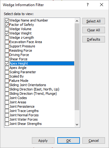
- Select OK.
The Wedge Info panel in the Sidebar should now include Apex Height.
Based on the Apex Height of the Roof Wedge (3.85 m), Lower Left Wedge (3.32 m), and Lower Right Wedge (2.59 m) we will use a Bolt Length of 5 m to support these wedges. We are not concerned with the Floor Wedge in this tutorial since it is stable and does not require support.
3.2 ADDING A BOLT PATTERN
Now we will add a Bolt Pattern that covers the sides and roof of the excavation. To add a Bolt Pattern:
- Select: Support > Add Bolt Pattern

- In the Add Bolt Pattern On Perimeter dialog:
- Set Length = 5.
- Leave all other values as is.
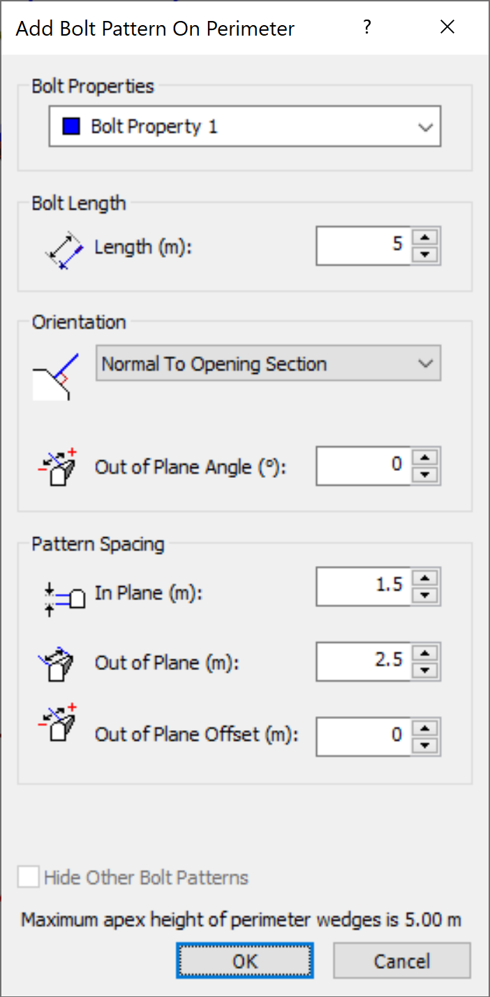
- Select OK.
Now we can add the Bolt Pattern graphically with the mouse, as follows:
- First of all, notice that as you move the mouse cursor a red cross-hair icon tracks along the opening section boundary and follows the mouse movement.
- Hover the mouse cursor over the lower-right vertex of the opening section (the vertex at 277.5, 306). When the red cross-hair cursor is exactly on the vertex (it will automatically snap to the nearest vertex), click the left mouse button. This will define the starting point for the Bolt Pattern.
- If you immediately see a Bolt Pattern around the entire opening section, don’t worry, this is normal. Move the mouse in a counter-clockwise direction around the opening section boundary and you will see the Bolt Pattern displayed as the mouse is moved.
Remember: a Bolt Pattern is always generated in a counter-clockwise direction around the opening section boundary. - When the red cross-hair cursor is at the lower-left vertex of the boundary (the vertex at 264.5, 303), click the left mouse button again, and the Bolt Pattern will be added to the model as shown in the following figure.
Notes:
- The spacing of the bolts along the boundary is 1.5 meters. This is the In-plane Spacing we used in the Add Bolt Pattern dialog.
- All bolts are normal (perpendicular) to the boundary segment on which they are located since we used the Normal orientation option in the Add Bolt Pattern dialog.
- The Bolt Pattern begins exactly on the first point that you clicked on, but it will not necessarily end exactly on the second point (unless the distance between the two points is an exact multiple of the in-plane spacing).
3.3 BOLT PROPERTIES
We will now discuss the properties of the bolts we have just installed. To define Bolt Properties:
- Select: Support > Bolt Properties

- The Bolt Properties dialog appears.

Bolt Properties Dialog - For this tutorial, we will initially use the default bolt type, which is a Mechanically Anchored bolt with a 0.1 MN capacity.Other bolt types available in UnWedge include Grouted Dowel, Cable Bolt, Split Set, and Swellex.
- Select Cancel.
This bolt property type ( Bolt Property 1) is already assigned to the Bolt Pattern (when we added the bolts with the Add Bolt Pattern dialog), so we do not need to assign the properties.
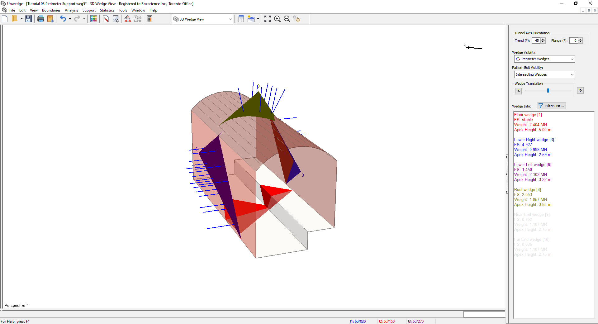
3.4 3D WEDGE VIEW
Now let’s take a look at the model in the 3D Wedge View.
- Select 3D Wedge View
 from the View dropdown on the toolbar or the View > Select View menu.
By default, only bolts that intersect the wedges are displayed.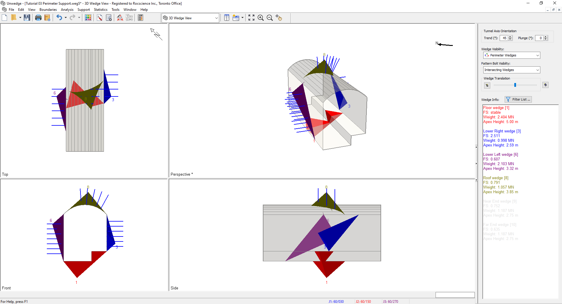
3D Wedge Model View - Maximize the Perspective view by double-clicking the Perspective pane.
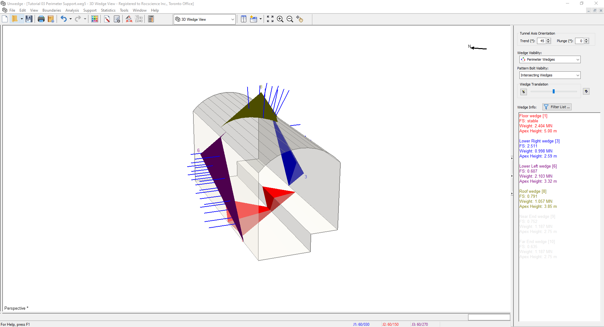
3D Wedge Model View - Use the mouse to rotate the model and observe how the bolts intersect the wedges.
- Click and drag on the wedges to move them away from the excavation. Note that the bolts remain in place and do not move with the wedges.
- Reset the wedges to their default position (click Reset Wedge Movement
 in the Sidebar or double click the middle mouse button).
 - To view ALL the bolts generated in the patterns, select All in the Sidebar Pattern Bolt Visibility dropdown. However, bolts that do NOT intersect a wedge have no effect on the analysis and do not affect the wedge Factor of Safety in any way.
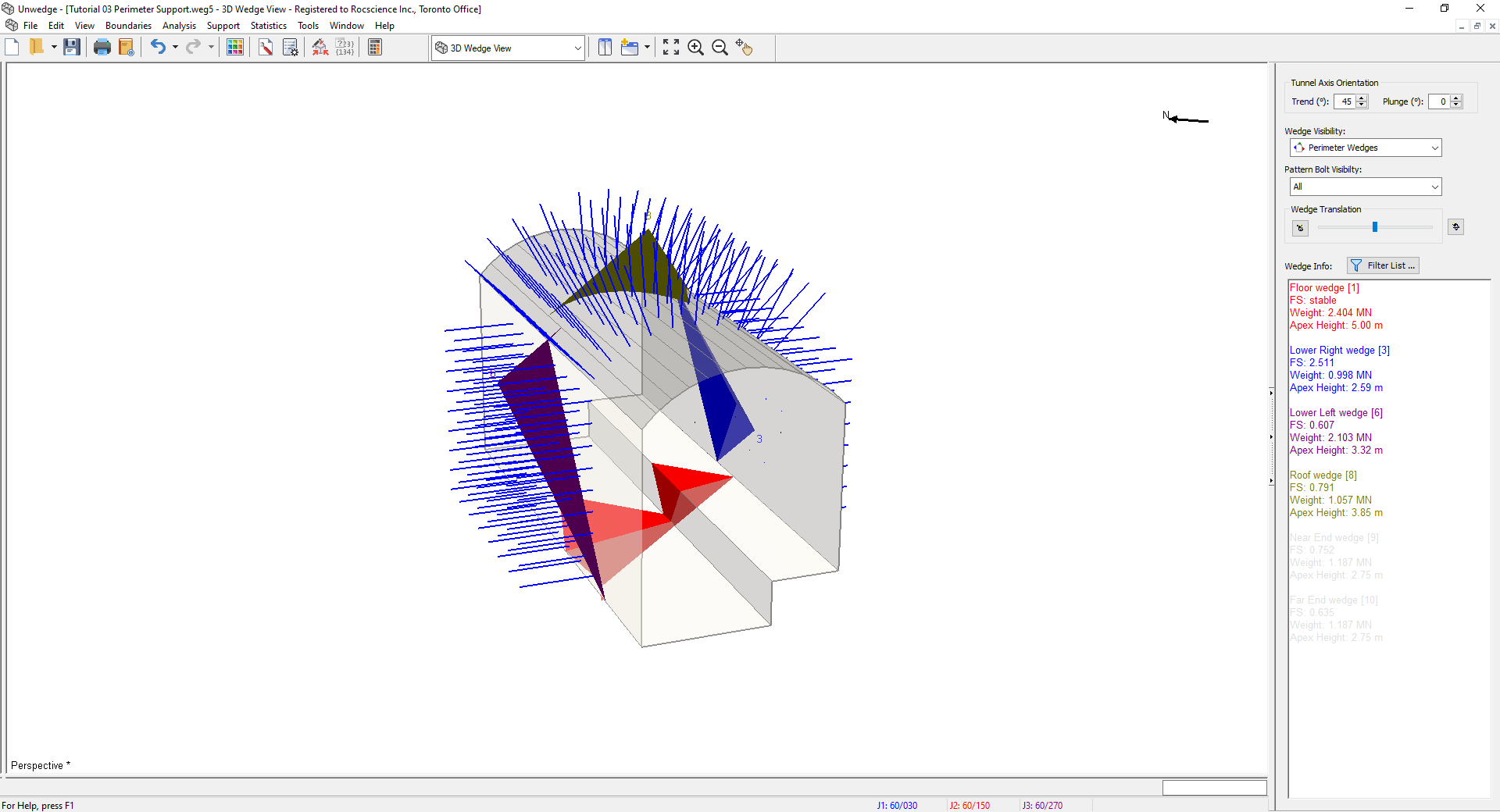
3D Wedge Model View Look at the Wedge Info panel in the Sidebar. The addition of the pattern bolt support has increased the wedge Factor of Safety as follows:
Factor of Safety
No Support
Pattern Bolt Support
Roof Wedge
0
0.791
Lower Left Wedge
0.210
0.607
Lower Right Wedge
1.059
2.511
- Reset the bolt visibility by selecting Intersecting Wedges in the Sidebar Pattern Bolt Visibility dropdown.
3.5 BOLT DATA TIPS
In the 3D Wedge View, bolt information can be displayed as popup Data Tips for individual bolts by hovering the mouse over any bolt that intersects a wedge. This information includes the Bolt Property Type, the length of the bolt that passes through the wedge ( Wedge Length), Anchorage Length, Bolt Failure Mode, Support Force, and Bolt Efficiency.
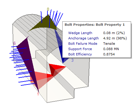
For this example (Mechanically Anchored bolts), the bolt support force that's applied to the wedge is equal to the bolt tensile capacity (0.1 MN) multiplied by the bolt efficiency. The bolt efficiency is a factor that is used to account for the bolt orientation and the fact that bolts may not be mobilized in pure tension. Bolt efficiency is a function of the bolt orientation relative to the direction of wedge movement. For complete details about how the Bolt Properties are used to determine the support force applied to a wedge, see Bolt Support Force in UnWedge.
- Restore the four-pane display by double-clicking in the Perspective view.
3.6 EDITING A BOLT PATTERN
The parameters of an existing Bolt Pattern can be easily edited with the Edit Bolt Pattern ![]() option. This allows you to change the Bolt Properties assigned, Orientation, Bolt Length, Pattern Spacing, etc.
option. This allows you to change the Bolt Properties assigned, Orientation, Bolt Length, Pattern Spacing, etc.
Notes:
- In the 3D Wedge View, the Edit Perimeter Bolt Pattern option is only available as a right-click shortcut.
- In the Perimeter Support Designer view, the Edit Bolt Pattern option is available from the toolbar, from the menu Support > Edit > Edit Bolt Pattern, or the right-click menu.
Since we are currently viewing the 3D Wedge View, let’s use the right-click shortcut method.
- Right-click on ANY bolt in the pattern in any pane.
- Select Edit Perimeter Bolt Pattern
 from the popup menu.
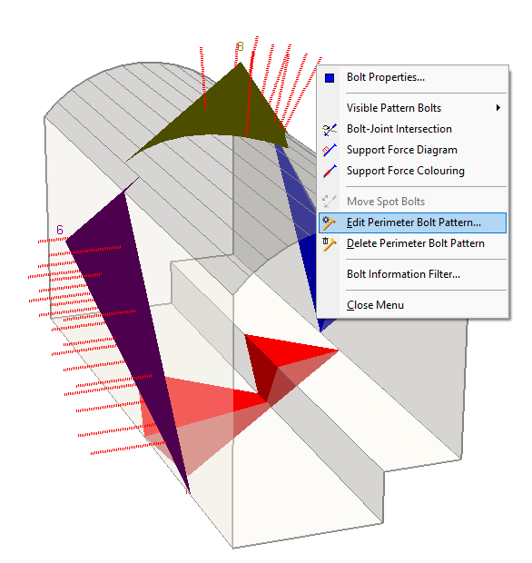
Edit Perimeter Bolt Pattern Selection from Rightclick Options - In the Edit Bolt Pattern On Perimeter dialog:
- Under Pattern Spacing, change the In Plane Pattern = 2 m
- Under Pattern Sapcing, change the Out of Plane = 2 m.
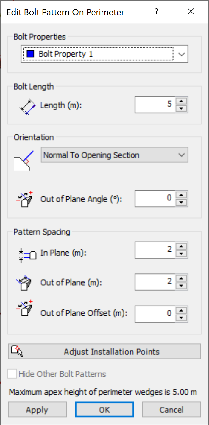
- Select OK.

Notice that the Factor of Safety of all three wedges has decreased slightly. This is because the new pattern spacing has resulted in fewer bolts that intersect the wedges.
3.6.1 Out of Plane Offset
The Out of Plane Offset option in the Edit Bolt Pattern dialog allows you to shift the origin of the Bolt Pattern in the direction of the tunnel axis. This can change the Factor of Safety by changing the position and number of bolts which intersect a wedge. By default, the Out of Plane Offset is zero, which simply means that the origin of the bolt pattern is at z = 0, which corresponds to the apex location of all Perimeter Wedges. Since the actual position of wedges is usually not known in advance, it is usually not possible to specify a meaningful value for the Out of Plane Offset. However, it does allow you to check the sensitivity of the wedge Factor of Safety to changes in the longitudinal position of the pattern.
3.6.2 Out of Plane Angle
By default, all bolts that are part of a Bolt Pattern will lie in the x-y plane and thus will be orthogonal to the extrusion (z) direction. Both end points of the bolt will have the same z coordinate. To angle the bolts out of plane (z-direction), the Out of Plane Angle option is used. The angle is measured in a plane containing both the bolt and the z-axis. The angle is measured from the bolt in the x-y plane (angle = 0).
As an optional exercise:
- Try different values of Out of Plane Offset and Out of Plane Angle in the Edit Bolt Pattern dialog, and observe the changes in Factor of Safety. You can enter positive or negative values for the Out of Plane Offset, so try values between -1 and +1 for example. If you select the Apply button in the dialog you can view the new results for each offset or angle value without closing the dialog. Observe the position of the bolt pattern and the values of Factor of Safety for each offset value. Switch to 3D Wedge View to see the angle of the bolts.
- In general, the Factor of Safety will be maximized at some particular value of Out of Plane Offset or Out of Plane Angle. However, the optimal value of offset may be different for each wedge.
- When you are finished, reset the Out of Plane Offset and Out of Plane Angle values to zero.
TIP: The Out of Plane Offset option can also be useful if you want to apply more than one Bolt Pattern (e.g., to use different bolt types) and you want to offset the different patterns by a given distance.
3.7 EDITING BOLT PROPERTIES
Now let’s try a different type of bolt. Since we are viewing the 3D Wedge View, we will use the right-click shortcut to access the Bolt Properties dialog.
- Right-click on ANY bolt in the pattern in ANY of the four panes.
- Select Bolt Properties from the popup menu.
The Bolt Properties dialog will appear.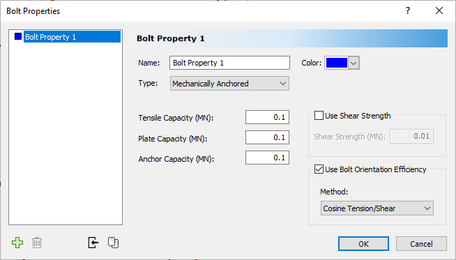
Bolt Properties Dialog - In the Bolt Properties dialog, change the Type to Swellex.
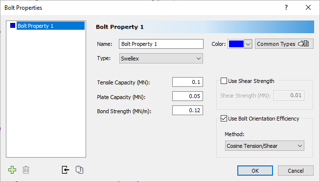
Bolt Properties Dialog - Select OK.
Notice that the Factor of Safety of the three wedges has decreased. Although the Swellex bolt tensile capacity (0.1 MN) is the same as the previous mechanically anchored bolt type, a Swellex bolt can also fail by pullout or stripping at the ends of the bolt if the bond strength or face plate capacity is exceeded. We will illustrate this by displaying the support force diagram for the bolts.
3.8 BOLT SUPPORT FORCE DIAGRAM
A bolt support force diagram in UnWedge displays the tensile support capacity along the length of the bolt (i.e., if a bolt intersects a wedge at a given point along the length of the bolt, what is the maximum possible tensile support force that can be supplied by the bolt?).

The support force diagram for bolts can be displayed in the 3D Wedge View as follows:
- First, maximize the Perspective view by double-clicking in the view.
- Right-click on any bolt and select Support Force Diagram from the popup menu.
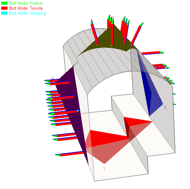
A representation of the support force diagram is displayed along the length of each bolt. - Zoom in and rotate the model as desired in order to see the support force diagrams.
For the Swellex bolts, note the three possible failure modes – Stripping, Tensile, Pullout. The failure modes are represented by different colours
After zooming and rotating, your screen may look as follows.
Other display options are available, for example:
- Right-click on any bolt and turn on the Bolt-Joint Intersection option (this displays a small marker at each bolt-wedge intersection).
- Click and drag the Roof wedge away from the excavation. Rotate the model as desired for better viewing of the intersection markers. This graphically illustrates how the failure mode for each bolt (stripping, tensile, pullout) corresponds to the position of the wedge-bolt intersection point on the support force diagram.
Before proceeding, reset the default viewing options (i.e., turn off the display of the bolt support force diagrams and bolt-joint intersections, reset the wedge position, select Zoom All ![]() , and double-click in the Perspective view to restore the four-pane display).
, and double-click in the Perspective view to restore the four-pane display).
4.0 Perimeter Support: Shotcrete
Now let’s add some shotcrete support to the cavern perimeter but, first, switch back to the Perimeter Support Designer view. The procedure for adding shotcrete to the perimeter is very similar to the method of adding a Bolt Pattern.
- Switch back to the Perimeter Support Designer View
 .
. - Select Add Shotcrete Layer
 from the toolbar or the Support menu.
The Add Shotcrete Layer On Perimeter dialog appears, which allows you to choose the Shotcrete Properties type.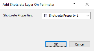
- We'll use the default Shotcrete Property 1.
- Select OK.
- Add the shotcrete layer graphically with the mouse, as follows:
- Firstly, notice that as you move the mouse cursor, a red cross-hair icon tracks along the opening section boundary, and follows the mouse movement.
- Hover the mouse cursor over the lower right vertex of the opening section (the vertex at 277.5, 306). When the red cross-hair cursor is exactly on the vertex (it will automatically snap to the nearest vertex), click the left mouse button. This will define the starting point for the shotcrete layer.
- If you immediately see the shotcrete layer around the entire opening section, don’t worry, this is normal. Move the mouse in a counter-clockwise direction around the opening section boundary, and you will see the shotcrete layer displayed as the mouse is moved. The shotcrete layer is displayed as a narrow coloured strip along the inside of the opening section boundary.
- Remember: A shotcrete layer is always generated in a counter-clockwise direction around the opening section boundary.
- When the red cross-hair cursor is at the lower left vertex of the boundary (the vertex at 264.5, 303), click the left mouse button again, and the shotcrete layer will be added to the model as shown in the following figure.
Look at the Wedge Info panel in the Sidebar and you can see that the addition of the shotcrete layer has greatly increased the Factor of Safety of the Roof, Lower Left, and Lower Right wedges.
Notes:
- Multiple layers of shotcrete can be added by repeating the above steps.
- The layers can be placed anywhere on the perimeter and can overlap in any manner.
- Each layer can have different properties.
It is left as an optional exercise to experiment with these options after completing this tutorial.
4.1 SHOTCRETE PROPERTIES
Properties of shotcrete are defined with the Shotcrete Properties option.
- Select Shotcrete Properties
 on the toolbar or the Support menu.
The Shotcrete Properties dialog appears.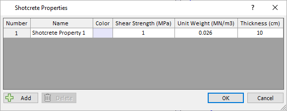
As you can see, the shotcrete properties are Shear Strength, Unit Weight, and Thickness. We have used the default properties (a layer with Thickness = 10 cm, and Shear Strength = 1 MPa).
Notes:
- The Shear Strength of the shotcrete multiplied by the thickness determines the passive support force that can be generated by the shotcrete per unit length of wedge perimeter (i.e., the exposed perimeter of the wedge at the excavation face). The assumed shotcrete failure mode is direct shear.
- The Unit Weight of the shotcrete is used to determine the total weight of shotcrete that has been applied to the face of a wedge. The shotcrete weight is added to the Wedge Weight and included in the stability calculations. The shotcrete weight can noticeably affect the Factor of Safety of a wedge if the thickness of the layer is significant.
Let’s define another shotcrete property type:
 button on the bottom-left of the Shotcrete Properties dialog.
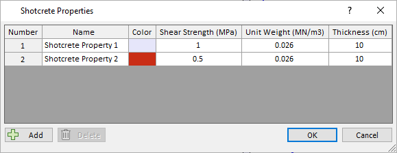
4.2 EDITING A SHOTCRETE LAYER
Now let’s assign the new shotcrete property to the existing shotcrete layer.
- Select Edit Shotcrete Layer on the toolbar or the Support > Edit menu.
- Left-click in the layer to select it.
- Right-click and select Done Selection
 in the popup menu.
The Edit Shotcrete Layer On Perimeter dialog appears.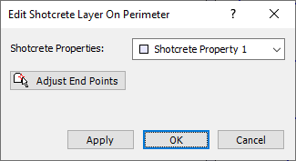
- Select Shotcrete Property 2 (i.e., the new shotcrete property type we defined) from the dropdown.
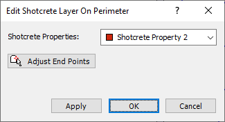
- Select OK.
The new Shotcrete Property is now applied to the perimeter shotcrete layer as you can see from its colour. The Factor of Safety of the wedges has decreased since the new shotcrete type has lower shear strength (0.5 MPa) than the previous shotcrete (1 MPa). The new shotcrete type could represent the shotcrete strength at an earlier age, for example.
TIP: If you hover the mouse over a shotcrete layer, you will see the properties of the layer displayed as a popup data tip.
4.3 DISPLAY OF SHOTCRETE IN 3D WEDGE VIEW
Finally, let’s see how shotcrete is displayed in the 3D Wedge View.
- Select 3D Wedge View from the View dropdown on the toolbar or from the View > Select View menu.
- Double-click in the Perspective view to maximize it.
As you can see, when shotcrete is applied to the excavation perimeter, it is displayed as semi-transparent shading on the perimeter where the shotcrete has been applied. The colour corresponds to the shotcrete colour defined in the Shotcrete Properties dialog. The display of shotcrete in the 3D Wedge View can be turned on or off in the Display Options dialog.
This concludes the tutorial. You are now ready for the next tutorial, Tutorial 04 - Joint Combinations in UnWedge.