9 - Probabilistic Support
1.0 Introduction
This tutorial will demonstrate probabilistic support in UnWedge by conducting a Probabilistic Analysis in which a Bolt Support Pattern is added to the roof of a section of an underground spiral access ramp.
Topics Covered in this Tutorial:
- Persistence
- Bolt Spacing
- Out of Plane Offset
- Random Offset
- Scatter Plot
Finished Product:
The finished tutorial can be found in the Tutorial 09 Probabilistic Support.weg5 file located in the Examples > Tutorials folder in your UnWedge installation folder.
2.0 Model
- If you have not already done so, run the UnWedge program by double-clicking on the UnWedge icon in your installation folder. Or from the Start Menu, select Programs > Rocscience > UnWedge.
If the UnWedge application window is not already maximized, maximize it now so that the full screen is available for viewing the model.
- For this tutorial, start by reading in the file Tutorial 02 Scaling Wedges_initial.weg5, which you can find in the Examples > Tutorials folder in your UnWedge installation folder and open.
2.1 PROJECT SETTINGS
- Open the Project Settings
 dialog from the toolbar or the Analysis menu.
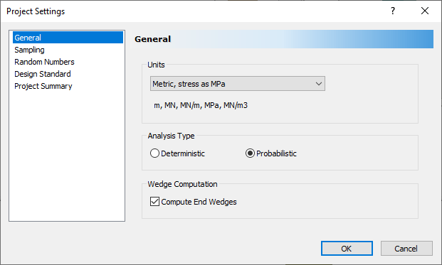
 - Ensure the Units = Metric, stress as MPa.
- Change the Analysis Type = Probabilistic.
- In the Sampling tab, ensure the Advanced Location Dependent Scaling box is checked.
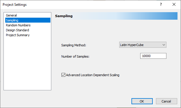
- Select OK.
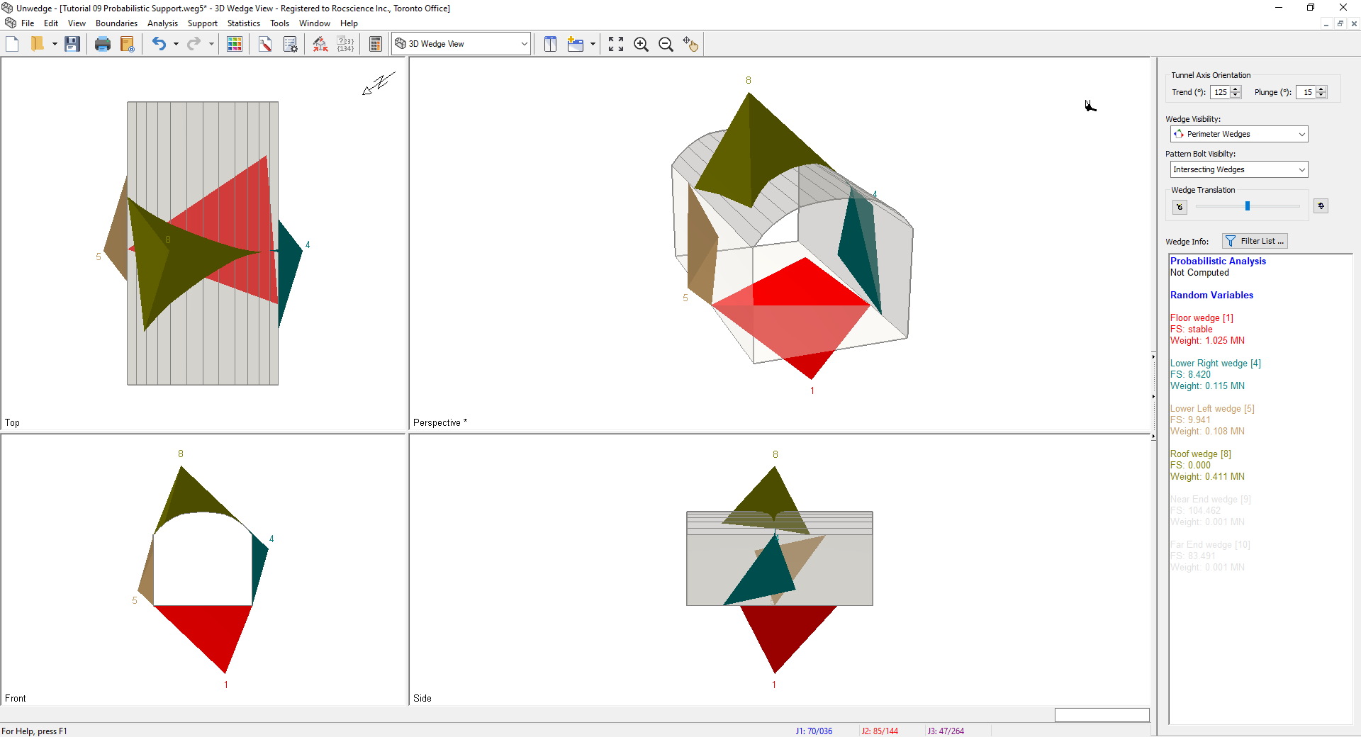
As you can see, all of the Perimeter Wedges (Roof, Sides, and Floor Wedges) are the maximum possible size for the excavation cross-section.
2.2 INPUT DATA
- Select Input Data
 from the toolbar or the Analysis menu.
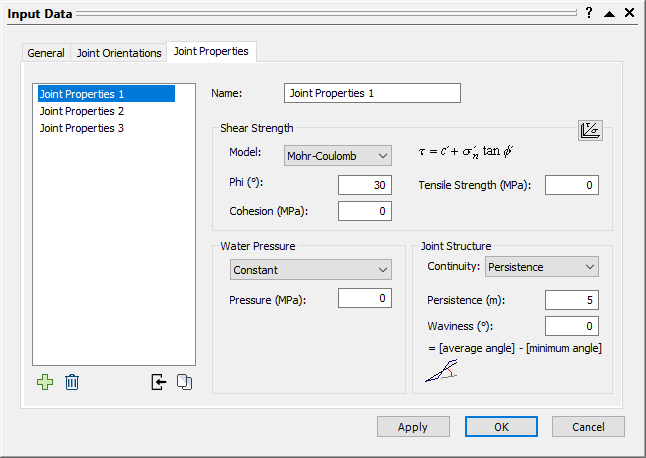
 - Select the Joint Properties tab.
- Under Shear Strength, set Cohesion = 0 MPa.
- Under Joint Structure, change Continuity from Infinite to Persistence. Set Persistence = 3 m.
- Repeat this process for Joint Properties 2 and Joint Properties 3.
- Select OK.
3.0 Probabilistic Input
We will only add variability to the Persistence values in this tutorial. All other values will be assumed to be exact.
- Select Statistics > Joint Properties
 .
.
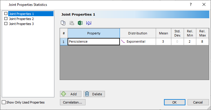
The Joint Properties Statistics dialog opens. - In the Joint Properties 1 tab, click Add
 button.
 - Change Property to Persistence.
- Set Distribution to Exponential.
- Set Mean = 3, Rel. Min = 2, and Rel. Max = 8.
- Repeat this process for Joint Properties 2, and Joint Properties 3.
- Select OK.
We are now ready to compute.
- Select Compute
 on the toolbar or the Analysis menu. This may take a couple of minutes.
4.0 Probability View
- Select Probability View
 on the View dropdown on the toolbar or the View > Select View menu.
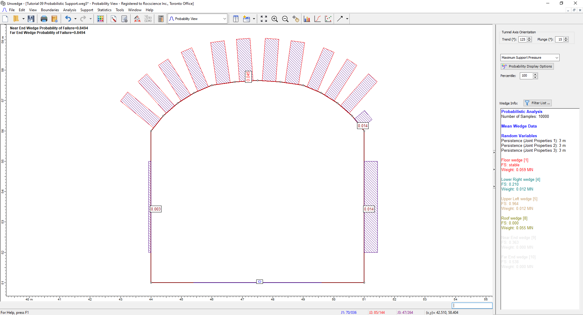
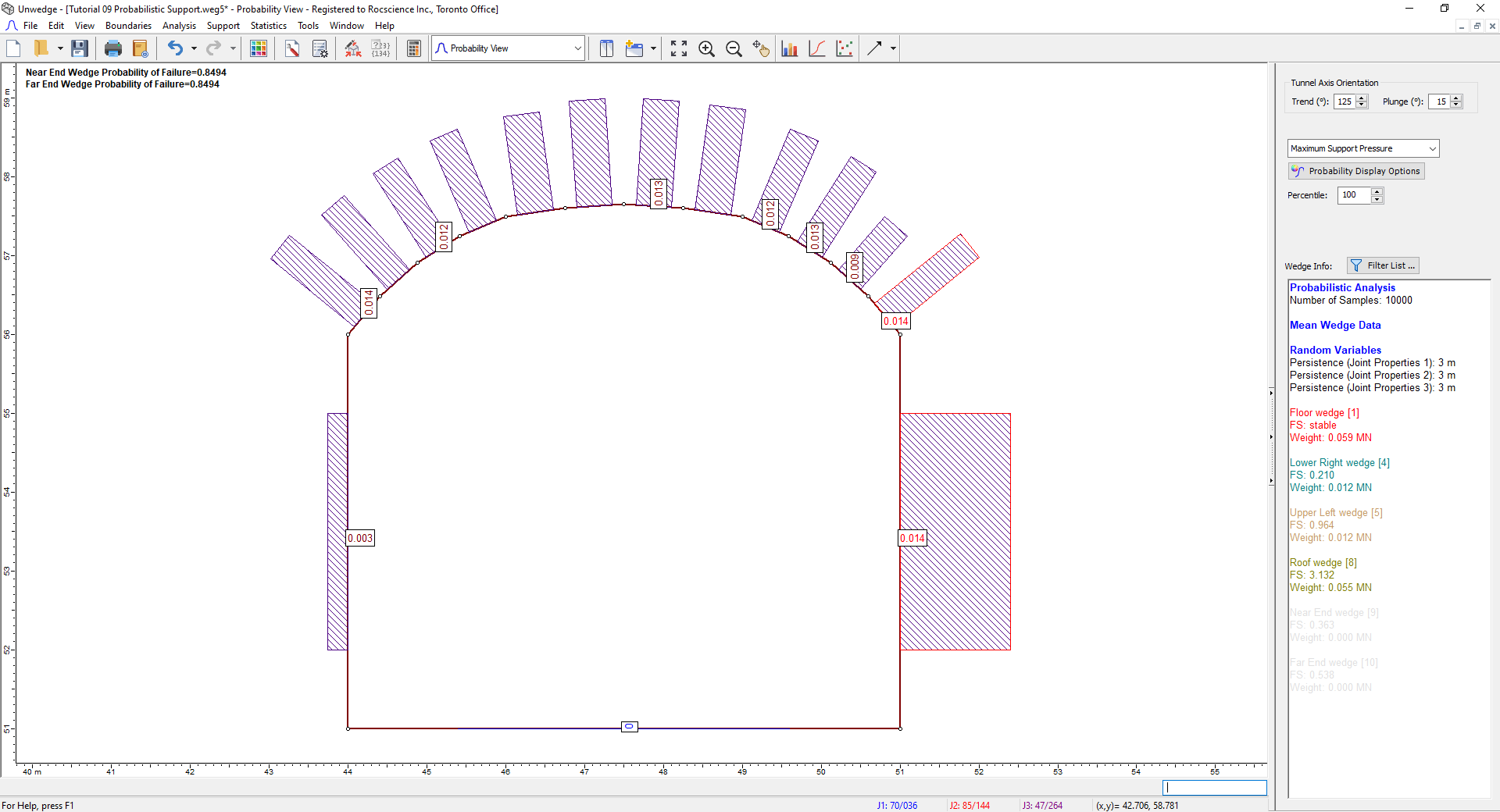
 - From the Sidebar on the right, we can see that the values on the screen represent the Maximum Support Pressure for each segment. The roof appears to have a Maximum Support Pressure of 0.045 MPa.
Probability Model View - From the drop-down menu on the Sidebar, select Maximum Wedge Depth.
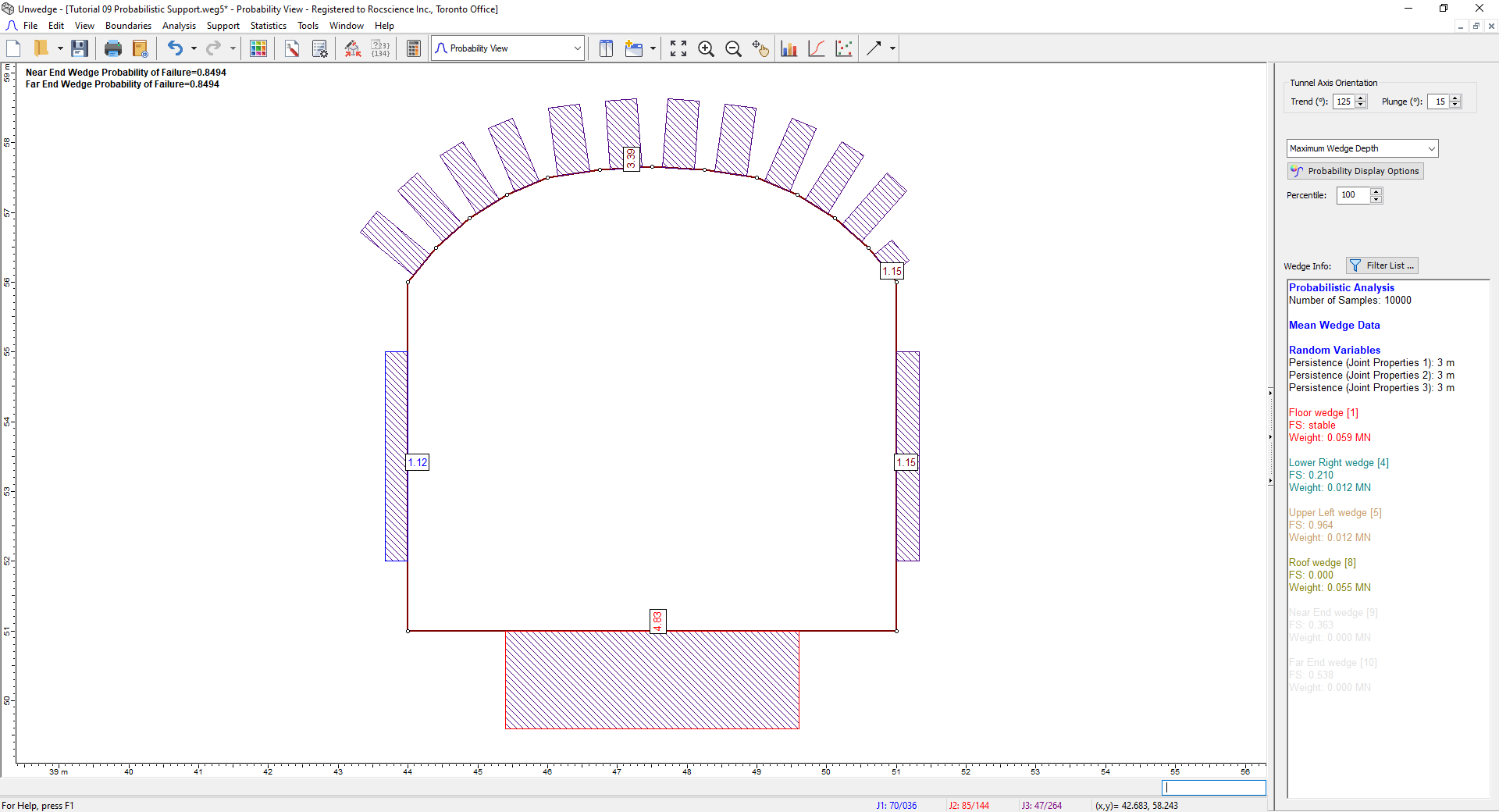
Probability Model View
Since the maximum roof wedge depths do not surpass 4 m, we will use 4 m long bolts.
5.0 Perimeter Support: Bolt Pattern
- Select Perimeter Support Designer
 on the View dropdown on the toolbar or the View > Select View menu.
 - Select Bolt Properties
 on the toolbar or the Support menu.
The Bolt Properties dialog appears. - Notice that the capacities of the default Mechanically Anchored bolt are 0.1 MN.
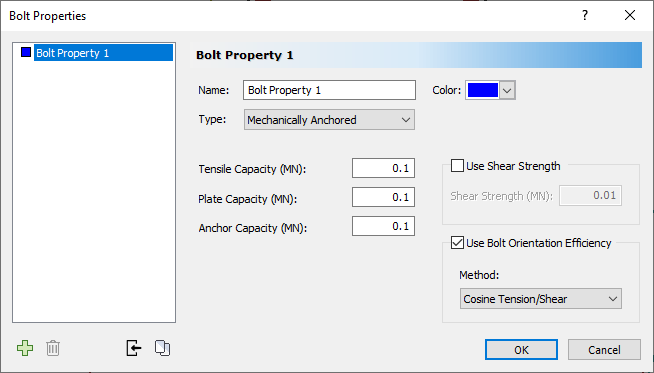
- Select Cancel.
If we used a bolt spacing of 2 m by 2 m, the resulting pressure, depending on offset, would be about:
0.1 MN / 4 m 2 = 0.025 MPa
which does not cover the 0.045 MPa Maximum Support Pressure we saw in the Probability View.
We will try to use a spacing of 1.5 m by 1.5 m instead: 0.1 MN / (1.5 m) 2 = 0.0444 MPa.
5.1 BOLT SPACING: 1.5M X 1.5M
- Select Add Bolt Pattern
 from the toolbar or the Analysis menu.
 - In the Add Bolt Pattern On Perimeter dialog:.
- Make sure Bolt Property 1 is selected in the Bolt Properties dropdown.
- Set Bolt Length = 4 m.
- Under Pattern Spacing, set In Plane = 1.5 m.
- Under Pattern Spacing, set Out of Plane = 1.5 m.
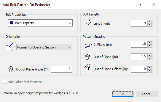
- Select OK.
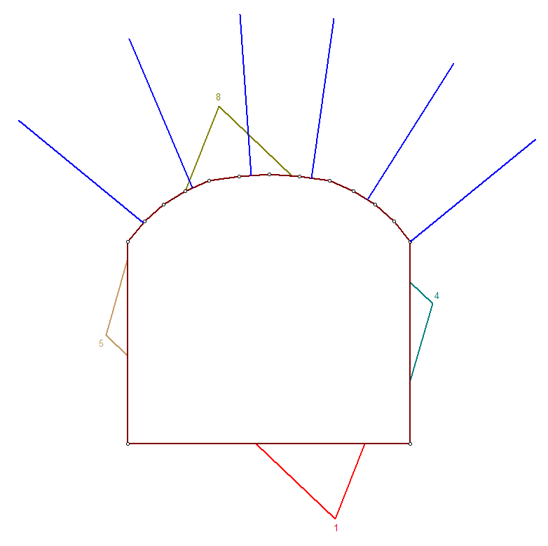
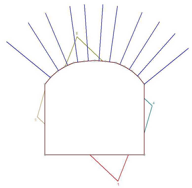
- Click on the right corner of the roof and then on the left corner of the roof (always going counterclockwise) to create a Bolt Pattern on the roof only, as shown.
We are now ready to compute.
- Select Compute on the toolbar or the Analysis menu. This may take a couple of minutes.
- Switch to the Probability View .
- Select Maximum Support Pressure from the dropdown on the Sidebar.
The Maximum Support Pressure on most of the roof segments has been greatly reduced, but it has not been eliminated. Therefore, we will try using a smaller bolt spacing.
5.2 BOLT SPACING: 0.75M X 0.75M
- Switch to the Perimeter Support Designer view.
- Right-click on a bolt and select Edit Bolt Pattern
 .
. - In the Edit Bolt Pattern On Perimeter dialog:
- Under Pattern Spacing, set In Plane = 0.75 m.
- Under Pattern Spacing, set Out of Plane = 0.75 m.
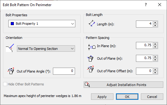
- Select OK.
We are now ready to compute.
- Select Compute on the toolbar or the Analysis menu. This may take a couple of minutes.
- Switch to the Probability View .
The Maximum Support Pressure on the majority of the roof segments is now zero. However, the right-most segment on the roof has a Maximum Support Pressure of 0.014 MPa. We will investigate this in the 3D Wedge View.
- Select New Window
 on the toolbar or the Window menu.
The Probability View should now be vertically tiled with the 3D Wedge View. - In the Probability View window, click on the right-most roof segment so it turns red.
The 3D Wedge View should be updated.
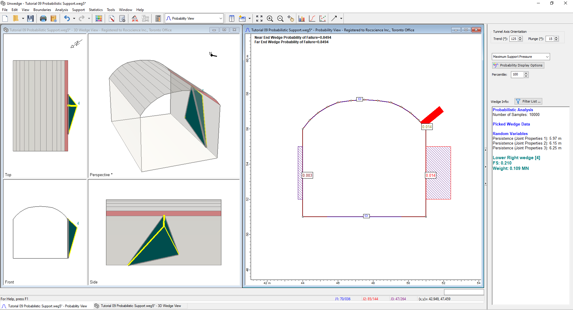
As we can see, the non-zero value is due to the right-side wedge that is intersecting the corner of the roof, as shown. Applying support to the right side of the tunnel will be left as an exercise for the user.
5.3 OUT OF PLANE OFFSET
- Close the 3D Wedge View and maximize the Probability View.
- Switch to the Perimeter Support Designer view .
- Right-click on a bolt and select Edit Bolt Pattern .

Notice that the Out of Plane Offset and Out of Plane Angle are currently set to 0. By default, a Bolt Pattern is positioned along the z-axis of the excavation, such that the pattern is aligned with the z = 0 coordinate. In UnWedge, z = 0 is the plane parallel to the Opening Section, which contains the apex of each Perimeter Wedge as drawn on the 3D Wedge View. To angle the bolts out of plane (z-direction), the out of plane angle option is used. The angle is measured in a plane containing both the bolt and the z-axis. The angle is measured from the bolt in the x-y plane (angle = 0). If you want to shift the position of the Bolt Pattern along the axis of the excavation, then enter a value for the Out of Plane Offset. The value of the Out of Plane Offset should be less than the value of the Out of Plane Spacing.
- Select Cancel.
The Out of Plane Offset option is useful if you wish to test the sensitivity of the Factor of Safety to the z-location of the pattern along the tunnel (e.g., run the analysis with zero offset, and then re-run it with the Out of Plane Offset set to half of the Out of Plane Spacing. It is also useful for offsetting the z-positioning of multiple Bolt Patterns (e.g., place a second pattern halfway between rows of the first pattern). It is an extremely important consideration when adding a Bolt Pattern.
The Out of Plane Offset can be defined as a statistical parameter so that you can evaluate the influence of the offset on wedge factors of safety. In this way, you can determine a distribution of Factor of Safety according to the offset and thus use the minimum Factor of Safety for design.
This section will look at the importance of out-of-plane offset on wedges supported by Bolt Patterns.
- Select Statistics > Bolt Properties
 .
. - In the Bolt Property Statistics dialog:
- Select the Use Random Bolt Offset checkbox.
This will apply a random offset to our pattern.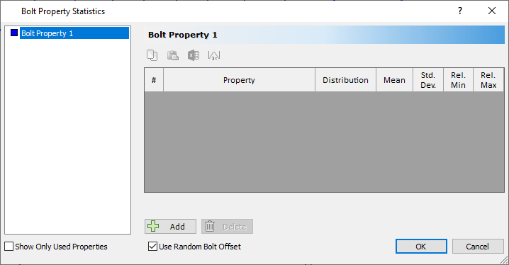
- Select OK.
We are now ready to compute.
- Select Compute on the toolbar or the Analysis menu. This may take a couple of minutes.
- Switch to the Probability View .
- Select New Window on the toolbar or the Window menu.
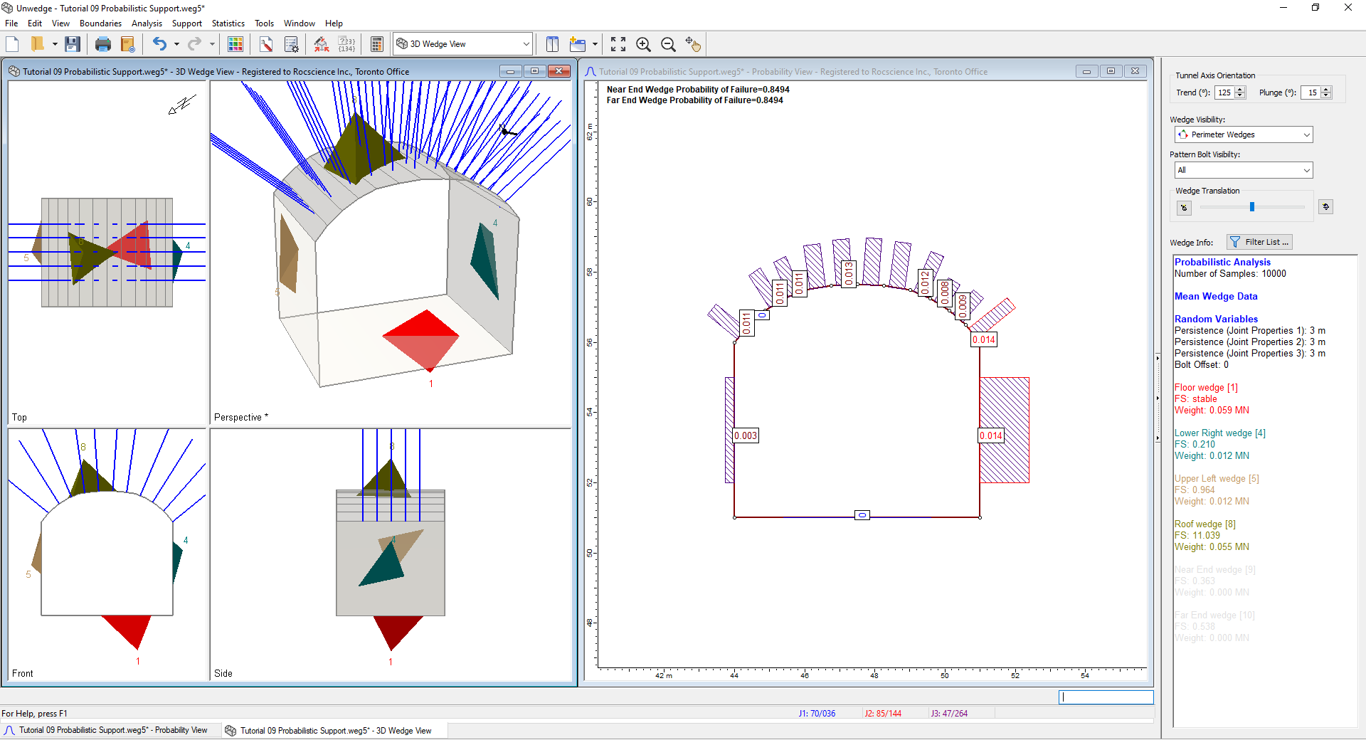
The Probability View should now be vertically tiled with the 3D Wedge View. - Click on the 3D Wedge View window and change the Pattern Bolt Visibility option on the Sidebar from Intersecting Wedges to All.
3D Wedge Model View
You should now see all the bolts on the roof. - In the Probability View window, click on one of the non-zero roof segments such that it turns red.
The 3D Wedge View should have updated.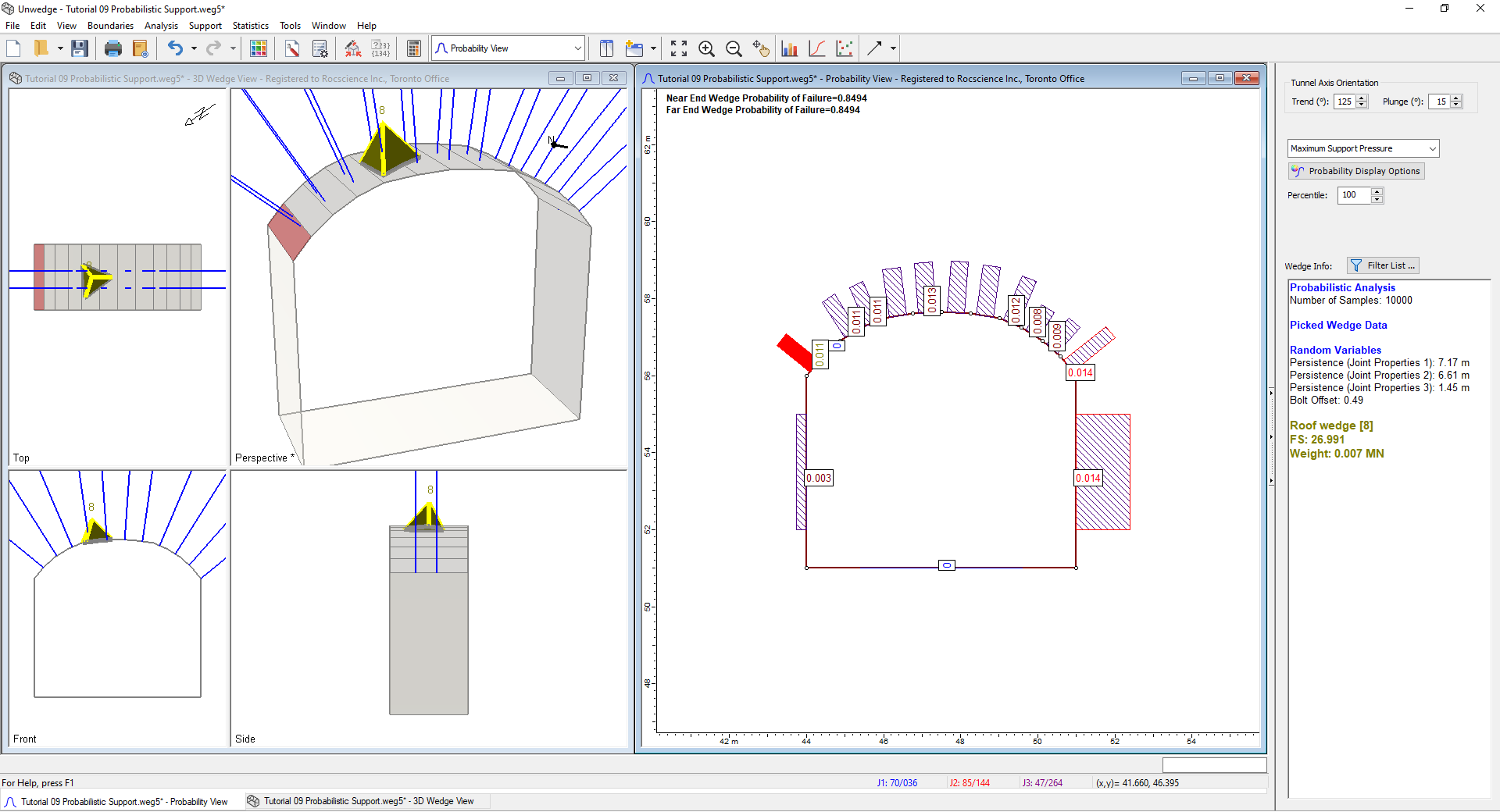
3D Wedge Model View
Examine the Perspective View. You will notice that several bolts bypass the roof wedge, as shown. This demonstrates that there are values of the offset that result in wedges not being intersected by any bolts. As a result, these wedges are completely unsupported and could fail, despite the default offset of zero resulting in all wedges being stable. It is important to investigate offset to ensure that large wedges that could fail secondary support systems such as wire mesh or shotcrete do not “sneak” through the Bolt Pattern.
6.0 Scatter Plot: Bolt Offset vs. Factor of Safety
- Right-click a segment in the Probability View.
- Select Plot Scatter
 on the popup menu.
The Scatter Plot Parameters dialog appears. - Set X-Axis Dataset = Bolt Offset, and Y-Axis Dataset = Factor of Safety.
- Select Location = Single Segment then select Segment 15 from the dropdown.
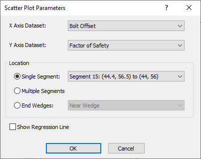
- Select OK.
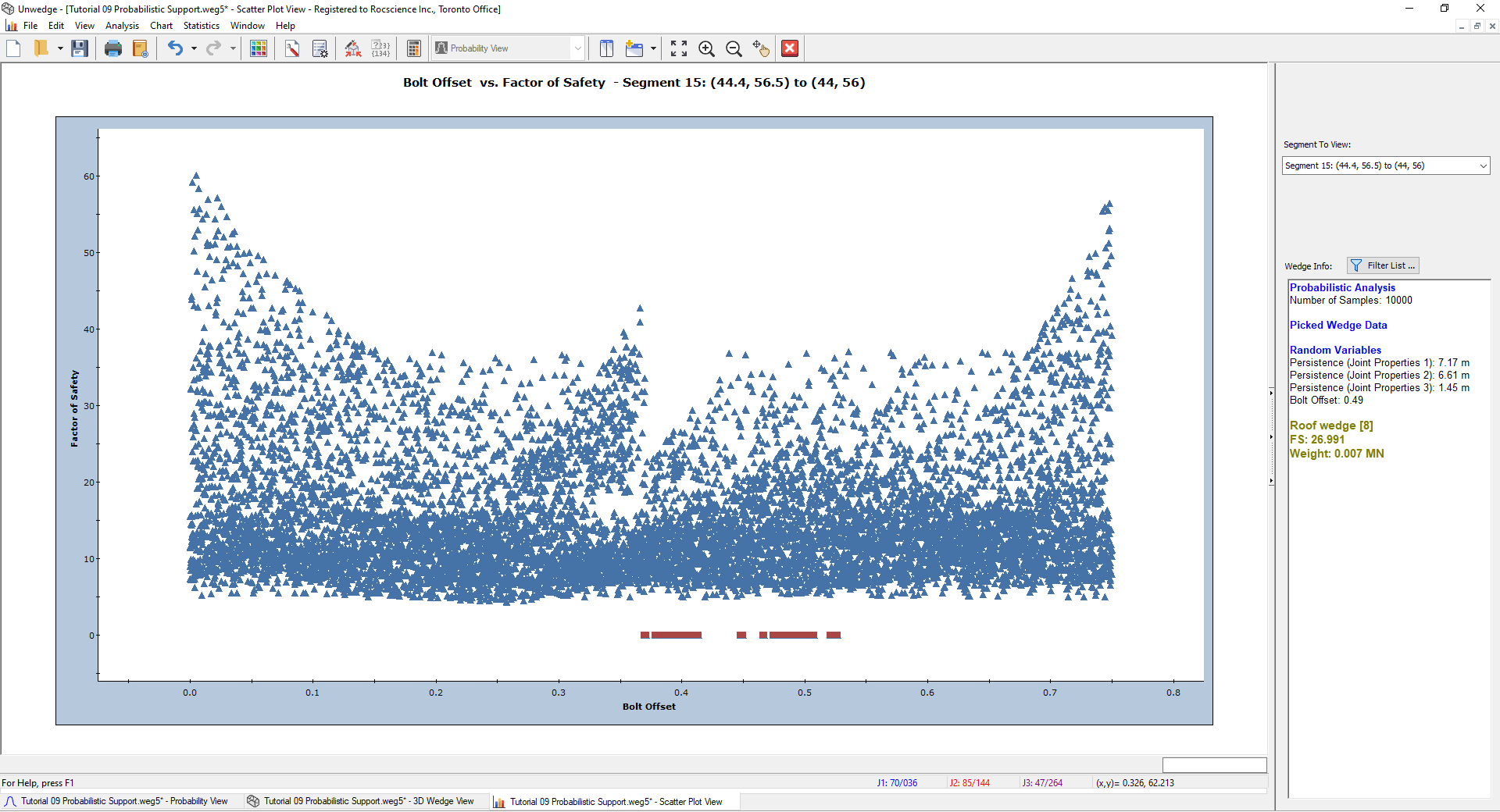
- Right-click on the plot and select Show Failed Wedges.
Your scatter plot should look as shown below. Notice the red dots in the image below. These values all have a Factor of Safety of zero, meaning they have failed. They represent the failed wedges from the 10,000 trials that were placed in between the bolts and hence did not receive any support.
This concludes the tutorial. You are now ready for the next tutorial, Tutorial 10 - Ground Surface in UnWedge.