2 - Scaling Wedges
1.0 Introduction
UnWedge always initially calculates the maximum-sized wedges that can form around an excavation. This tutorial demonstrates how to scale down the size of wedges according to field measurements such as Joint Trace Length, Joint Persistence, Wedge Face Area, etc.). Wedge scaling is important because the assumed wedge size can have a significant effect on the Factor of Safety and support requirements (e.g., pattern spacing, positioning or orientation of bolts, and the thickness or strength of shotcrete).
Topics Covered in this Tutorial:
- Scaling using Persistence and Trace Length
- Scaling Tunnel Length
- Scaling Wedge Size
- Scaling All Wedges
- Scaling Individual Wedges
- Factor of Safety and Scaling
Finished Product:
The finished product of this tutorial can be found in the Tutorial 02 Scaling Wedges.weg5 file, located in the Examples > Tutorials folder in your UnWedge installation folder.
2.0 Model
- If you have not already done so, run the UnWedge program by double-clicking the UnWedge icon in your installation folder or by selecting Programs > Rocscience > UnWedge > UnWedge in the Windows Start menu.
If the UnWedge application window is not already maximized, maximize it now so that the full screen is available for viewing the model.
For this tutorial we will start by reading in the file Tutorial 02 Scaling Wedges_initial.weg5 which you should find in the Examples > Tutorials folder in your UnWedge installation folder. The model represents a section of an underground spiral access ramp.
- Select
 File > Recent Folders > Tutorials Folder.
 - Open the Tutorial 02 Scaling Wedges_initial.weg5 file.
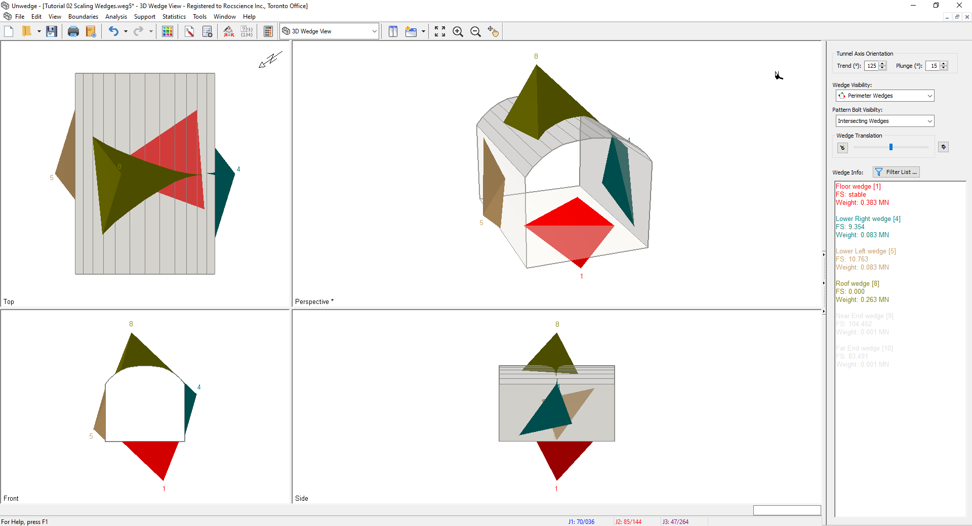
You should see the following view.
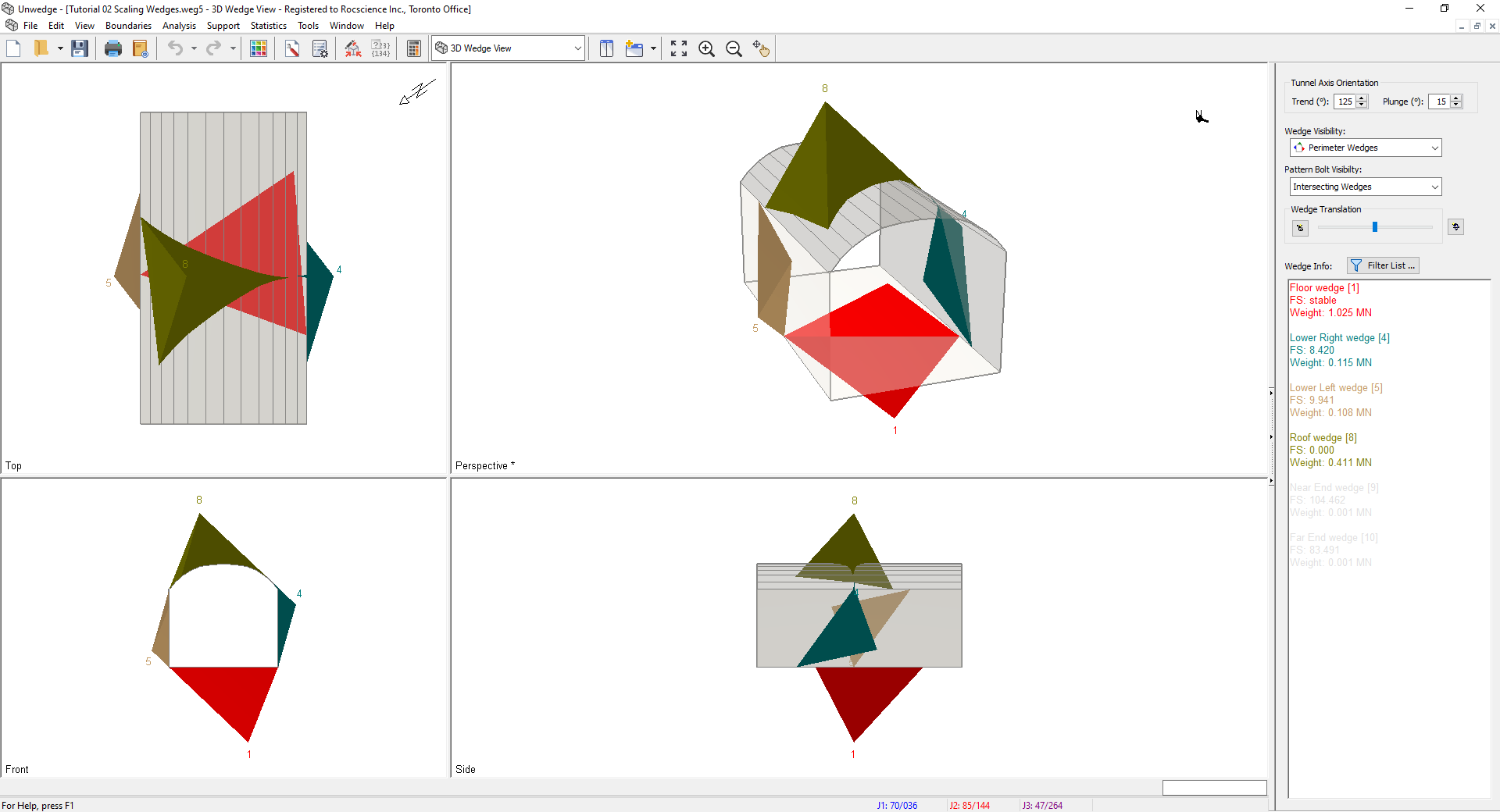
As you can see, all of the Perimeter Wedges (roof, sides and floor wedges) are the maximum possible size for the excavation cross-section.
3.0 Scaling Wedges
We will first scale the wedges using the options in the Input Data dialog.
3.1 SETTING TUNNEL LENGTH
- Select Input Data
 on the toolbar or the Analysis menu.
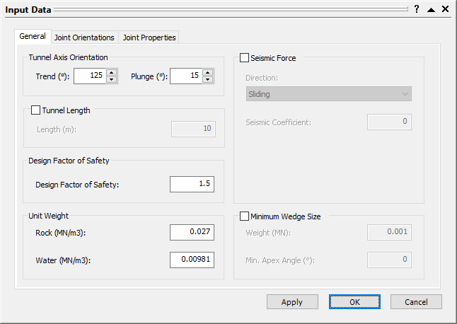
Input Data Dialog
Note that in the General tab you can scale down the length of the tunnel itself. Let's assume the Length of the tunnel is 10 m. - Select the Tunnel Length checkbox.
- Set Length = 10 m.
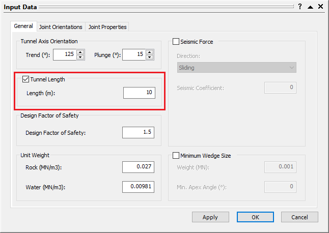
Input Data Dialog - Click Apply to see the changes.
3.2 SCALING USING JOINT 1 PERSISTENCE
We will now scale the wedges themselves first using Persistence.
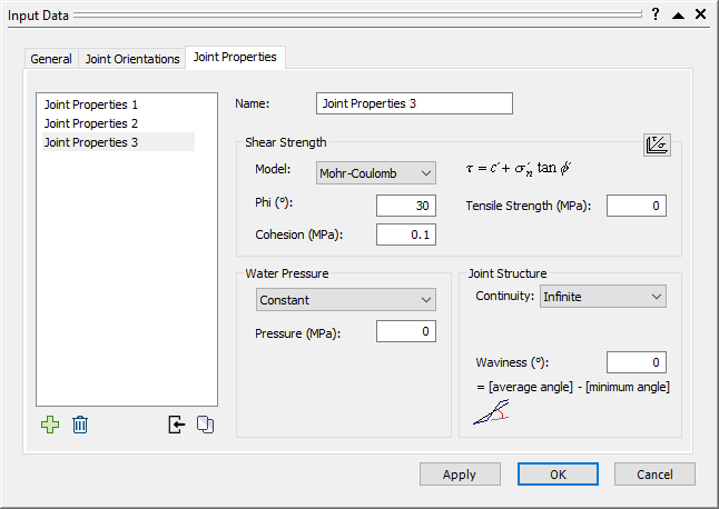
- Select the Joint Properties tab.
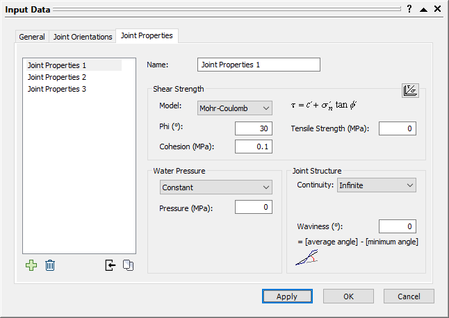
Input Data Dialog - Select Joint Properties 1 in the Joint Properties list.
- Under Joint Structure, set the Continuity = Persistence.
- Keep the default Persistence = 5 m.
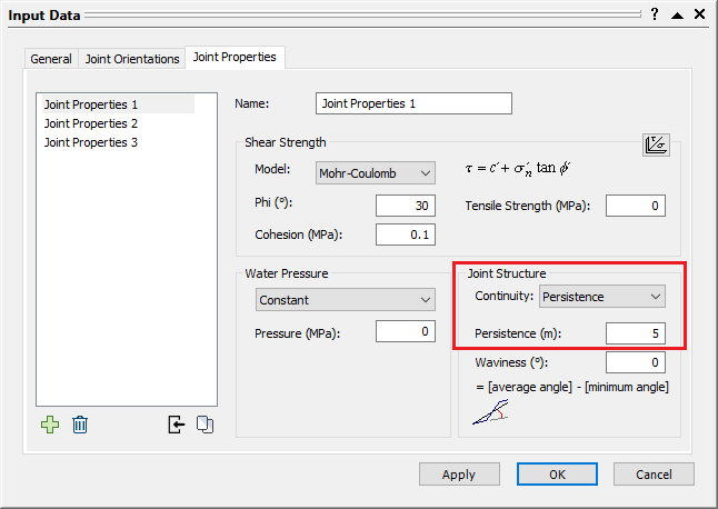
Input Data Dialog - Select OK.
All wedges should now have been scaled.
To display the scaling data in the Wedge Info panel:
- In the Sidebar, click the Wedge Info Filter List
 button.
 - In the Wedge Information Filter dialog, click the Defaults button to ensure the default data is displayed in the panel.
- Select the Scaled By and Joint Persistence checkboxes.
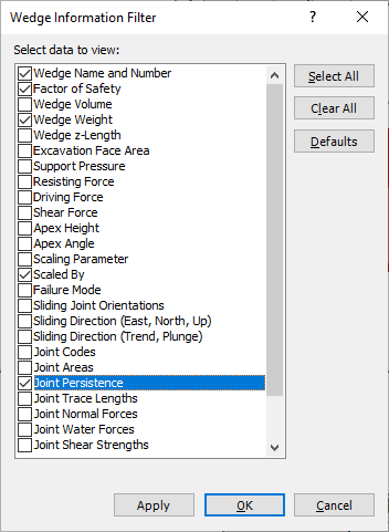
- Select OK.
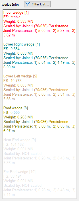
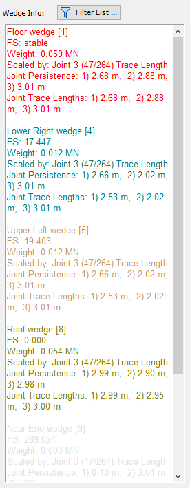
In the Wedge Info panel, we can now see that all wedges have been scaled by Joint 1 and that the Joint Persistence for Joint 1 of each wedge is 5 m, as expected.
3.3 SCALING USING JOINT 3 TRACE LENGTH
We will now scale the wedges using the Joint 3 Trace Length.
- Re-open the Input Data dialog from Analysis > Input Data .
- Select the Joint Properties tab.
- Select Joint Properties 3 in the Joint Properties list.
Input Data Dialog - Under Joint Structure, change Continuity = Trace Length.
- Set Trace Length = 3 m.
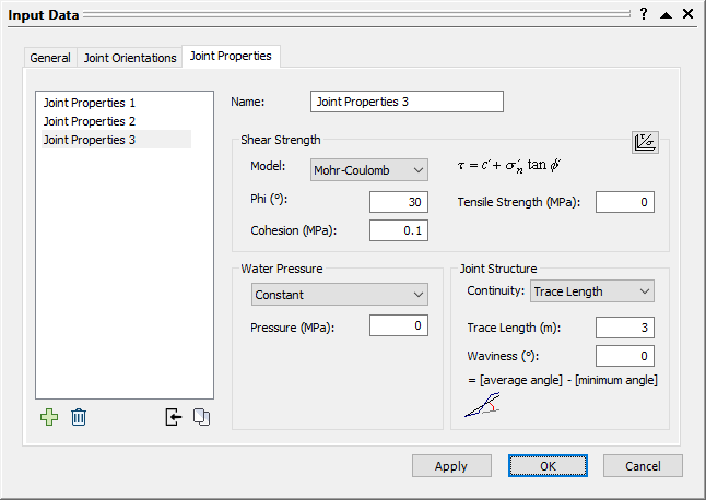
Input Data Dialog - Select OK.
To display the new scaling data in the Wedge Info panel:
- In the Sidebar, click the Wedge Info Filter List button.
- Select the Joint Trace Lengths checkbox.
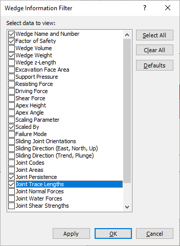
- Select OK.
In the Wedge Info panel, you should now see that all four wedges have been scaled by the Joint 3 Trace Length of 3 m. Because the Trace Length we entered for Joint 3 resulted in smaller wedges than the Persistence we entered for Joint 1, UnWedge has scaled all wedges the Joint 3 Trace Length.
4.0 Scaling Wedges: Advanced
We will now use the Scale Wedges option, which provides a more advanced way of scaling wedges.
- Select Scale Wedges on the Analysis menu.
The Scale Wedges dialog appears.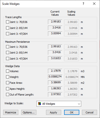
Scale Wedges Dialog
In this dialog, wedge size can be scaled according to Joint Trace Length, Joint Persistence, or Wedge Data (e.g., Volume, Weight). Although we can enter multiple scaling parameters at the same time, let’s enter parameters one at a time to see the results at each step. - Under Trace Lengths, select the Joint 1 checkbox.
- Set Scaling Value = 4 m
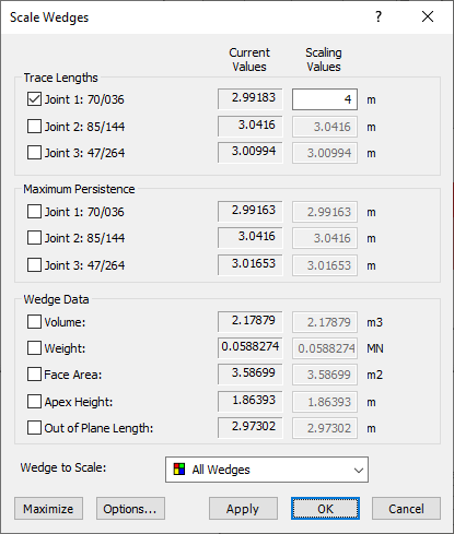
Scale Wedges Dialog - Select OK.
Note that all of the Joint 1 Trace Lengths displayed in the Sidebar have stayed the same. This is because we have already scaled Joint 1 with a Trace Length of 3 m and UnWedge chooses the smallest wedge size when several different scaling values are imputed. This demonstrates that the Scale Wedges dialog works in conjunction with the scaling options in the Input Data dialog.
To indicate that scaling has been applied to a wedge, the letter “ s” is displayed beside the wedge number (e.g., the roof wedge is numbered 8s). If you do not see the wedge numbers, go to Display Options  , select the Wedge Views tab, and make sure the Wedge Numbers checkbox is selected.
Now let’s enter one more scaling parameter:
- Re-open the Scale Wedges dialog from Analysis > Scale Wedges.
- Under Trace Lengths, select the Joint 2 checkbox.
- Set Scaling Value = 2.8 m.
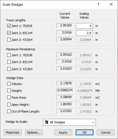
Scale Wedges Dialog - Select OK.
Look at the Wedge Info panel in the Sidebar. The results are now as follows:
- For the Floor (or Lower Right) and the Roof wedges, Scaled By = Joint 2 Trace Length and Joint 2 Trace Length = 2.8 m. The Joint 2 Trace Length (scaling value) is now the governing parameter.
- For the Upper Left and Lower Right wedges, Scaled By = Joint 3 Trace Length and Joint 3 Trace Length = 3 m. The Joint 3 Trace Length (scaling value) is still the governing parameter since the Joint 2 Trace Lengths are already less than 2.8 m and, therefore, the Joint 2 Trace Length scaling value does not affect these wedges.
This illustrates the following important points:
- When you enter more than one Scaling Value, a given wedge is ultimately scaled by only one parameter – the parameter that gives the smallest wedge size.
- Furthermore, if Wedge to Scale = All Wedges (in the Scale Wedges dialog) and you have entered multiple scaling values, the governing scaling parameter can be different for different wedges.
5.0 Position of a Scaled Wedge
For Perimeter Wedges that span multiple segments of the Opening Section (e.g., the Roof wedge in this example), UnWedge uses an algorithm that searches for the wedge with the maximum volume for the given Scaling Value(s). An iterative process is required to find this wedge. This determines the position of the scaled wedge on the perimeter.
For wedges that are formed on a single flat surface of the excavation boundary, the searching algorithm is not applicable, and the scaled wedge position will be approximately centred on the surface.
6.0 Scaling Individual Wedges
So far in this tutorial, we have considered all wedges for scaling, using the same set of scaling values. It is also possible to consider individual wedges for scaling. This allows you to enter independent scaling values for any desired wedge(s).
To select individual wedges for scaling:
- You can select the desired wedge from the Wedge to Scale dropdown in the Scale Wedges dialog.
- You can also right-click directly on a wedge and select Scale Wedge for that particular wedge from the popup menu, as shown in the following figure. This displays the Scale Wedges dialog with the wedge already selected in the dialog.
For example:
- Right-click on the 8 Roof wedge.
- Select Scale Wedge: 8 Roof from the popup menu.
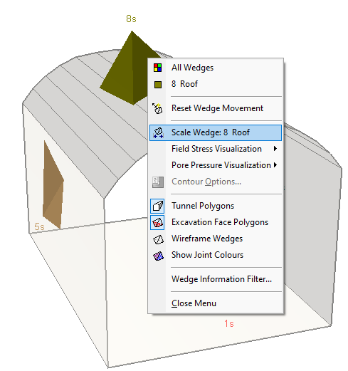
3D View of Model Right Click Options - In the Scale Wedges dialog under Trace Lengths, select the Joint 2 checkbox
- Set Scaling Value = 2 m.
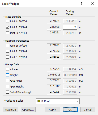
Scale Wedges Dialog - Select OK.
Look at the Wedge Info panel and note that the Roof wedge is now scaled by Joint 2 Trace Length = 2 m. All other wedges are still scaled as before.
You can scale any or all wedges individually in this manner. When you select individual wedges to scale, the scaling value parameters are entered independently for each wedge, and the dialog will “remember” the scaling values you have entered for each wedge.
6.1 RESETTING THE MAXIMUM WEDGE SIZE
To reset all wedges to the maximum size, select the Maximize button in the Scale Wedges dialog. This will clear all of the scaling values, for All Wedges and also for any individual wedge scaling values you have entered. However, it will not clear the Persistence and Trace Length values entered in the Input Data dialog.
7.0 Factor of Safety and Scaling
We will now briefly discuss the effect of scaling the wedge size on the wedge Factor of Safety and support requirements.
7.1 EFFECT OF JOINT STRENGTH
- Frictional Strength Only: If the shear strength of the joint planes is purely frictional (cohesion = 0), changing the size of an unsupported wedge will NOT change the Factor of Safety. You can verify this for the current example (the Joint Shear Strength of all joints is given by Phi = 30 degrees, cohesion = 0).
- Friction and Cohesion: If the shear strength of the joint planes includes a non-zero cohesion, the Factor of Safety of a wedge will, in general, depend on the size of the wedge.
- Other Parameters: Water pressure, field stress and other parameters can also influence the dependence of wedge size and Factor of Safety.
7.2 SUPPORT
If support has been applied to a wedge (e.g., bolts, or shotcrete), in general, changing the size of a wedge will affect the Factor of Safety. This can be due to several factors:
- The wedge size may affect the number of bolts that intersect a wedge (pattern bolting).
- The wedge size will affect the relative embedded lengths of a bolt. For a bonded bolt, the length that passes through the wedge and the length embedded in the rock mass will determine the support force applied to the wedge.
- If shotcrete has been applied, the wedge size will have a direct effect on the exposed perimeter length of the wedge face. This has a direct effect on the support force that is applied by the shotcrete.
- In conclusion, wedge scaling is of particular importance during support design since the assumed wedge size can have a significant effect on the pattern spacing, positioning, or orientation of bolts, and the thickness or strength of shotcrete. Wedge support is discussed in the next tutorial.
This concludes the tutorial. You are now ready for the next tutorial, Tutorial 03 - Perimeter Support in UnWedge.