17 - Vertical Shaft
1.0 Introduction
This tutorial demonstrates the Vertical Shaft analysis mode in UnWedge. Here, we will be taking a look at the effects of water pressure at various depths along the shaft.
Topics Covered in this Tutorial:
- Vertical Shaft
- Water Pressure
Finished Product:
The finished product of this tutorial can be found in the Tutorial 17 Vertical Shaft.weg5 file, located in the Examples > Tutorials folder in your UnWedge installation folder.
2.0 Model
- If you have not already done so, run the UnWedge program by double-clicking the UnWedge icon in your installation folder or by selecting Programs > Rocscience > UnWedge > UnWedge in the Windows Start menu. When the program starts, a default model is automatically created.
If the UnWedge application window is not already maximized, maximize it now so that the full screen is available for viewing the model.
For this tutorial, we will start by reading in the file Tutorial 17 Vertical Shaft_initial which you should find in the Examples > Tutorials folder in your UnWedge installation folder. The model is Deterministic and contains both perimeter and end supports.
- Select File
 > Recent Folders > Tutorials Folder.
 - Open the Tutorial 17 Vertical Shaft_initial file.
You should see the following view.
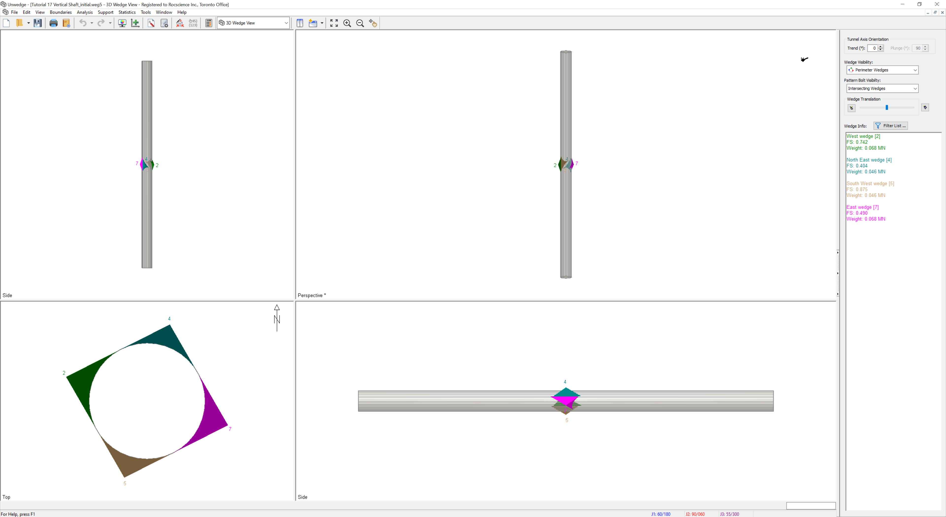
This is a vertical shaft with a diameter of 5 m and is 100 m deep.
2.1 PROJECT SETTINGS
- Open the Project Settings
 dialog from the toolbar or the Analysis menu.
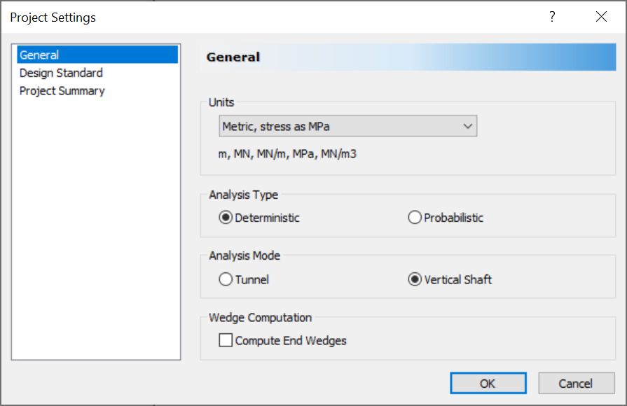
- Note that the Analysis Mode is set to Vertical Shaft which constrains the tunnel axis plunge to 90 degrees.
- Since this is a vertical shaft, the Compute End Wedges is unchecked under Wedge Computation.
- Select Cancel to close the dialog.
3.0 Water Pressure
Suppose that we have a water table right at the ground surface.
- Select Analysis > Input Data.
- Navigate to the Joint Properties tab of the Input Data dialog.
- Set the Water Pressure = Distance Above Roof End.
- Set the Phreatic Surface Offset Distance = 0 m.
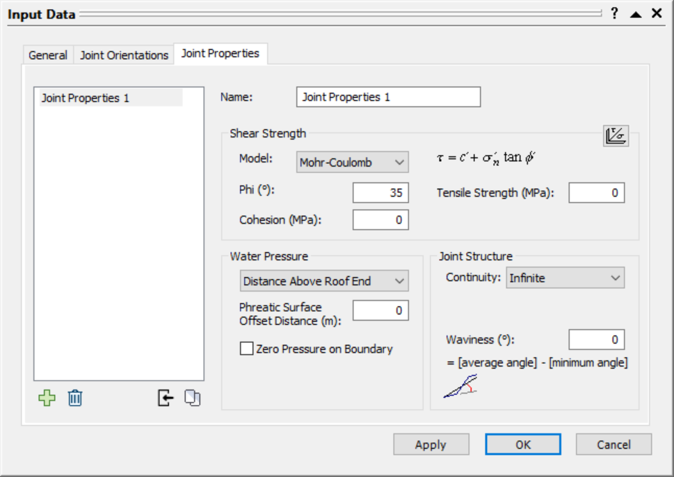
- Select OK.
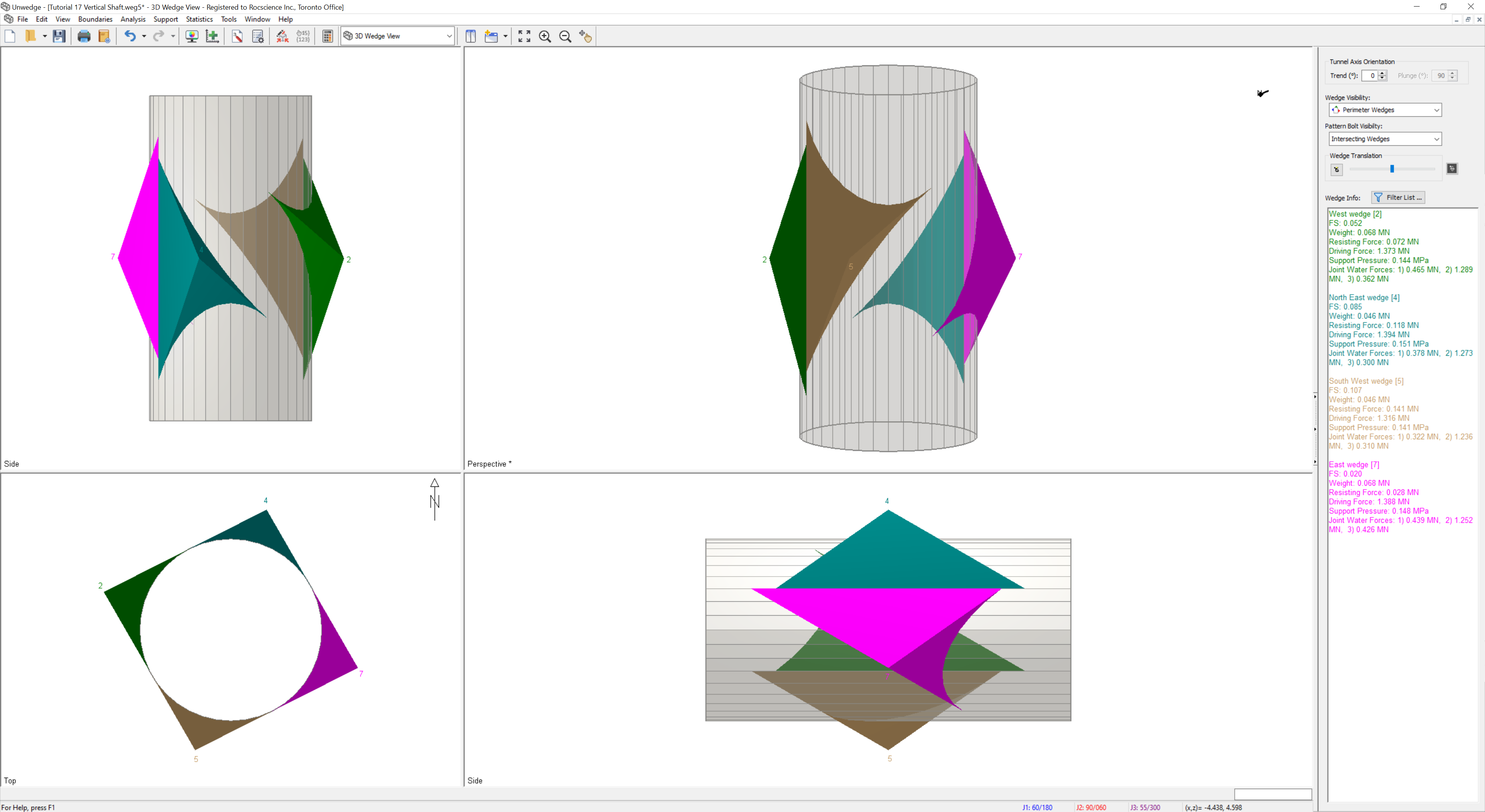
Note that the Factors of Safety for all 4 valid perimeter wedges have decreased due to the effects of water pressure in the joints.

3.1 WEDGE LOCATION
UnWedge automatically places the wedge apex at the z = 0 location along the shaft (somewhere about halfway along the length, at a depth of 50 m), although technically, they can occur anywhere along the shaft.
The deeper the wedges are located along the shaft, the greater the water pressure acting in the joints.
3.2 SHAFT LENGTH
To perform a sensitivity analysis on the wedge depth along the shaft, we will limit the Length to 10 m, and increase the Phreatic Surface Offset Distance by 10 m to model the effects of increasing water pressure for every 10 m down the shaft.
- Select Analysis > Input Data.
- Navigate to the General tab of the Input Data dialog.
- Check the Tunnel Length checkbox.
- Set the Length = 10 m.
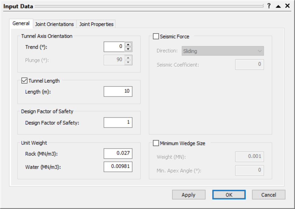
- Select OK.
Turn on the Resisting Force, Driving Force, Support Pressure, and Joint Water Forces Wedge Info display in the sidebar, if you have not done so already. To do so:
- Select Filter List button in the sidebar.
- Ensure that Resisting Force, Driving Force, Support Pressure, and Joint Water Forces checkboxes are selected.
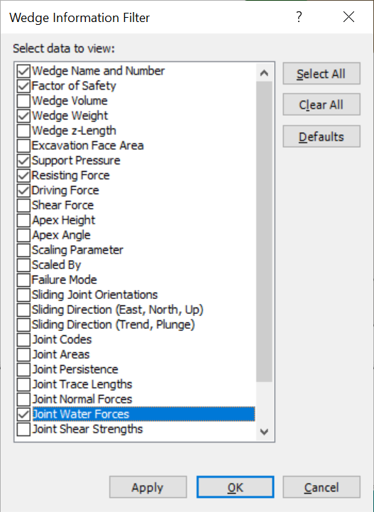
- Select OK.
With the Phreatic Surface Offset Distance set to 0 m above the roof end, East Wedge [7] has lost contact along all three joints.

3.3 PHREATIC OFFSET DISTANCE
- Select Analysis > Input Data.
- Navigate to the Joint Properties tab of the Input Data dialog.
- Set the Phreatic Surface Offset Distance = 10 m.

- Select Apply.
Note that the Joint Water Forces and Driving Force increases, as expected. Note that the changes in Factor of Safety are mixed. For the West wedge [2] and the South West wedge [5], the Factor of Safety decreases. For the North East wedge [3] and East wedge [7], the Factor of Safety increases. Depending on the joint geometry, increasing water pressure can increase the Factor of Safety if the component normal to the sliding joint is greater than the component in the sliding direction, and vice versa.
- Now keep increasing the Phreatic Surface Offset Distance by 10 m increments (i.e., Phreatic Surface Offset Distance = 20 m, 30 m, 40 m, 50 m, 60 m, 70 m, 80 m, 90 m) in the Input Data dialog.
TIP: The above sensitivity analysis could be easily automated using the Automate from Excel feature.
Take note of the Factor of Safety, Joint Water Force, Driving Force, Resisting Force, and Support Pressure for each wedge.
4.0 Results
As we would expect, the Joint Water Force for all joints steadily increases as we increase the depth of the wedges. While the Factor of Safety is not very sensitive to changes in the Phreatic Surface Offset Distance, the required Support Pressure is. The deeper the wedges, the more Support Pressure is required to obtain the Design Factor of Safety.
As the Joint Water Force increases on the joints, the Driving Force increases, as the water pressure pushes the wedge into the excavation. Due to the joint geometry (tetrahedral with unequal joints), the water pressure also effectively pushes the wedge onto the sliding joint, thereby increasing the Normal Force acting on the sliding joint. Since the joint strength is modelled by Mohr-Coulomb with only Friction Angle, the only element that affects the Resisting Force is the Normal Force acting on the sliding joint.
This concludes the tutorial.