16 - Truncation Surface and Planes
1.0 Introduction
This tutorial demonstrates the effects of truncating wedges in UnWedge.
Topics Covered in this Tutorial:
- Perimeter Truncation Surface
- End Truncation Planes
- Effects of Truncation on Wedges
- Effects of Truncation on Supports
Finished Product:
The finished product of this tutorial can be found in the Tutorial 16 Truncation Surface and Planes.weg5 file, located in the Examples > Tutorials folder in your UnWedge installation folder.
2.0 Model
- If you have not already done so, run the UnWedge program by double-clicking the UnWedge icon in your installation folder or by selecting Programs > Rocscience > UnWedge > UnWedge in the Windows Start menu. When the program starts, a default model is automatically created.
If the UnWedge application window is not already maximized, maximize it now so that the full screen is available for viewing the model.
For this tutorial, we will start by reading in the file Tutorial 16 Truncation Surface and Planes_initial which you should find in the Examples > Tutorials folder in your UnWedge installation folder. The model is Deterministic and contains both perimeter and end supports.
- Select File
 > Recent Folders > Tutorials Folder.
 - Open the Tutorial 16 Truncation Surface and Planes_initial file.
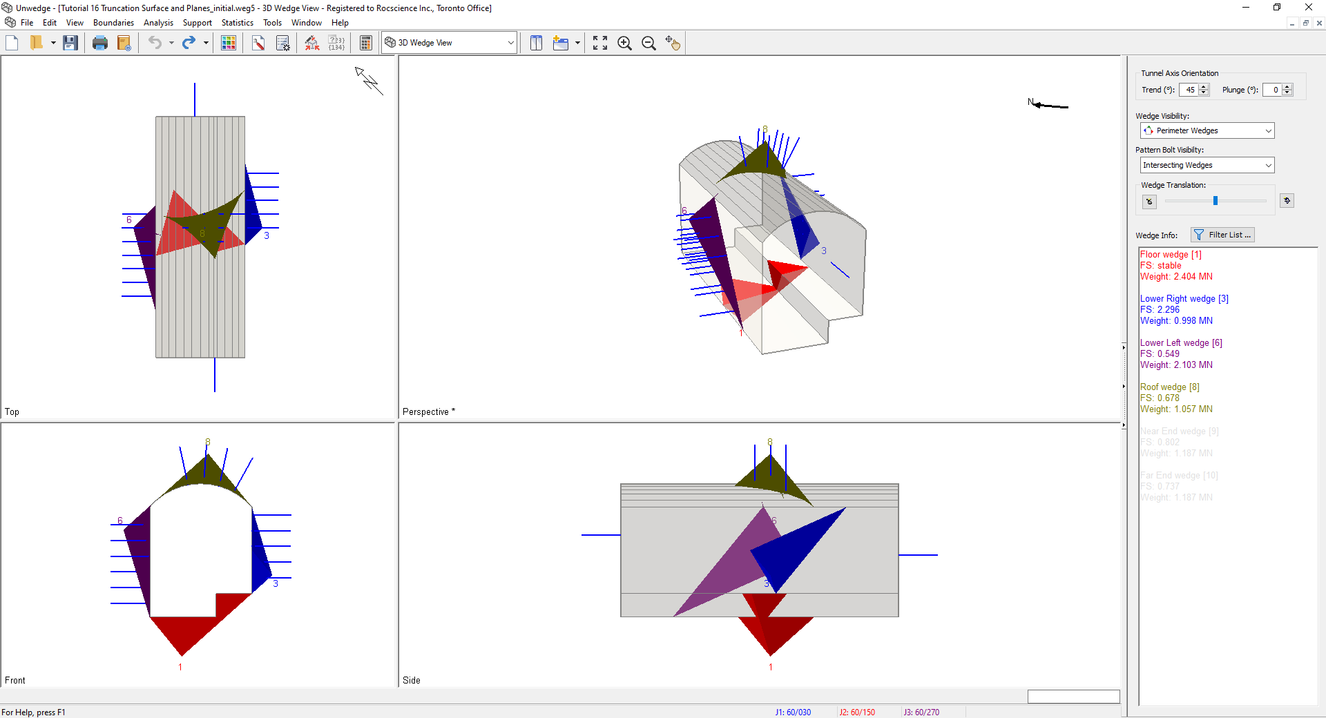
You should see the following view.
3.0 Truncation Surface and Planes
3.1 PERIMETER TRUNCATION SURFACE
The Truncation Surface feature in UnWedge is made up of surfaces which run in the direction of the tunnel axis. These surfaces truncate any Perimeter Wedges with which it intersects while allowing supports to penetrate. Keep in mind that the wedge geometry and bolt intersections will be affected.
To add a Truncation Surface, go to any of the 2D section views (i.e., Opening Section, End Wedges, Perimeter Support Designer, End Support Designer).
- Navigate to the Perimeter Support Designer
 view to better visualize the Perimeter Wedges and the Perimeter Supports.
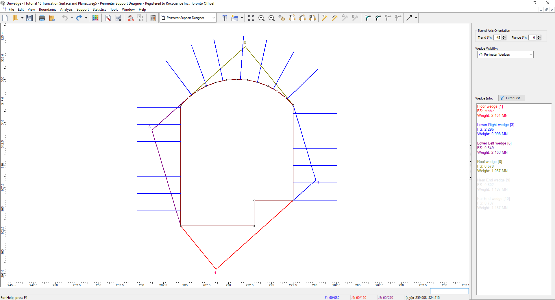
Perimeter Support Designer Model View - Select Boundaries > Add Truncation Surface
 .
. - Type coordinates 260, 321 followed by ENTER in the Prompt.
- Type coordinates 280, 321 followed by ENTER in the Prompt.
- Type ENTER again to finish drawing the truncation surface polyline.
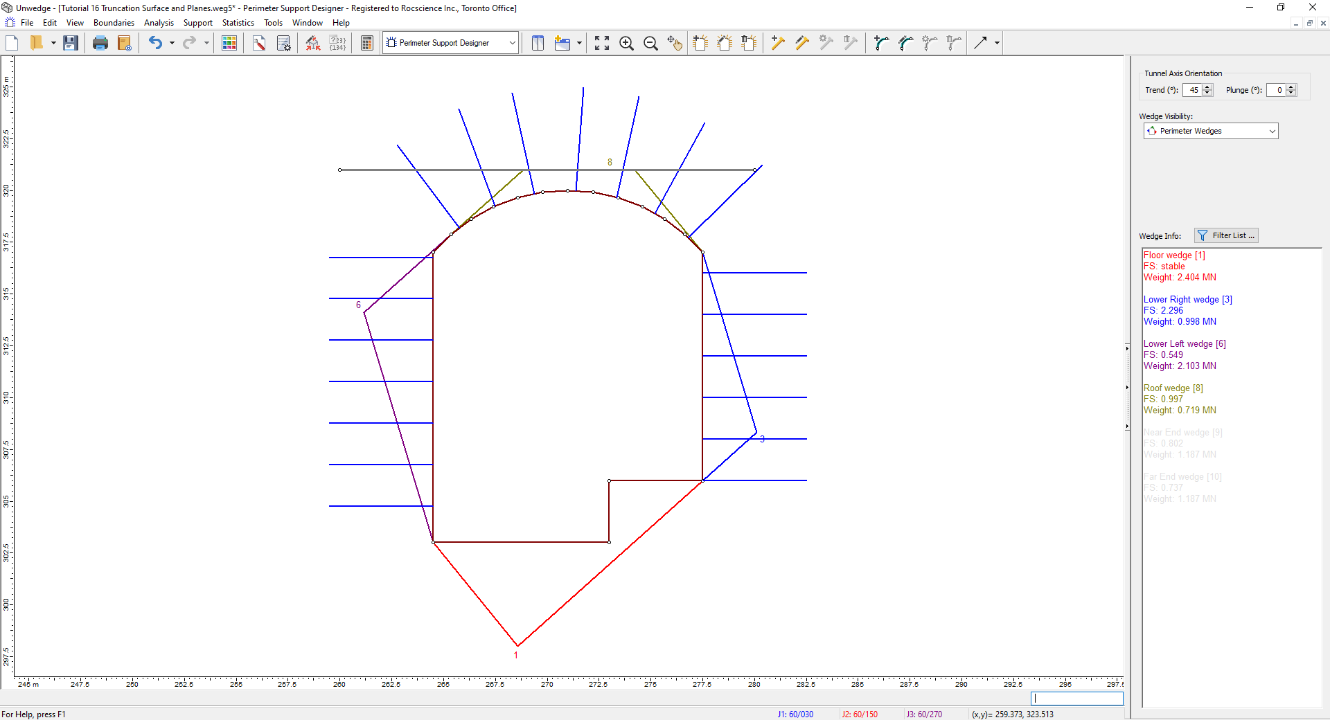
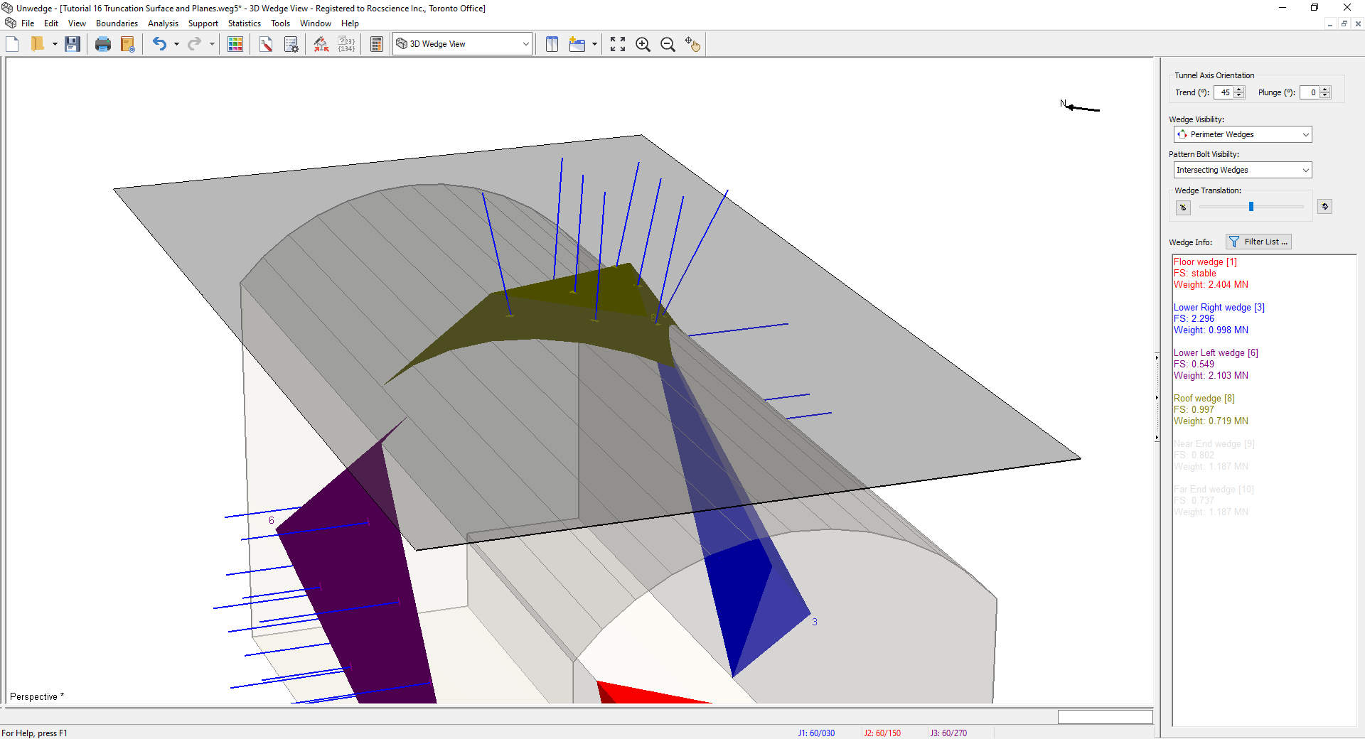
Perimeter Support Designer Model View The upper "Roof wedge [8]" has been truncated by the Truncation Surface. The wedge volume, weight, joint areas, and associated forces and factor of safety are affected by the truncation.
- Right-click on a bolt.
- Select Bolt-Joint Intersection.
Navigate to the 3D Wedge View  .
.
Notice that some of the bolt intersections on "Roof wedge [8]" now lie on the truncation face. The bond length of the bolt inside and outside the wedge is affected.
3.2 END TRUNCATION PLANES
The End Truncation Plane feature in UnWedge is made up of a plane parallel to the tunnel opening, at some offset distance. These planes truncate any End Wedges with which it intersects with while allowing supports to penetrate. Keep in mind that the wedge geometry and bolt intersections will be affected.
To add an End Truncation Plane:
- Select Boundaries > End Truncation Plane
 .
. - In the End Truncation Plane dialog:
- Check Near End Truncation.
- Under Near End Truncation, set Plane Offset Distance = 0.5 m.
- Check Far End Truncation.
- Under Set Far End Truncation, set Plane Offset Distance = 0.5 m.
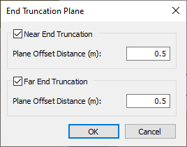
- Select OK to close the dialog.
In the 3D Wedge View, set the Wedge Visibility = All Wedges to visualize the End Wedges.
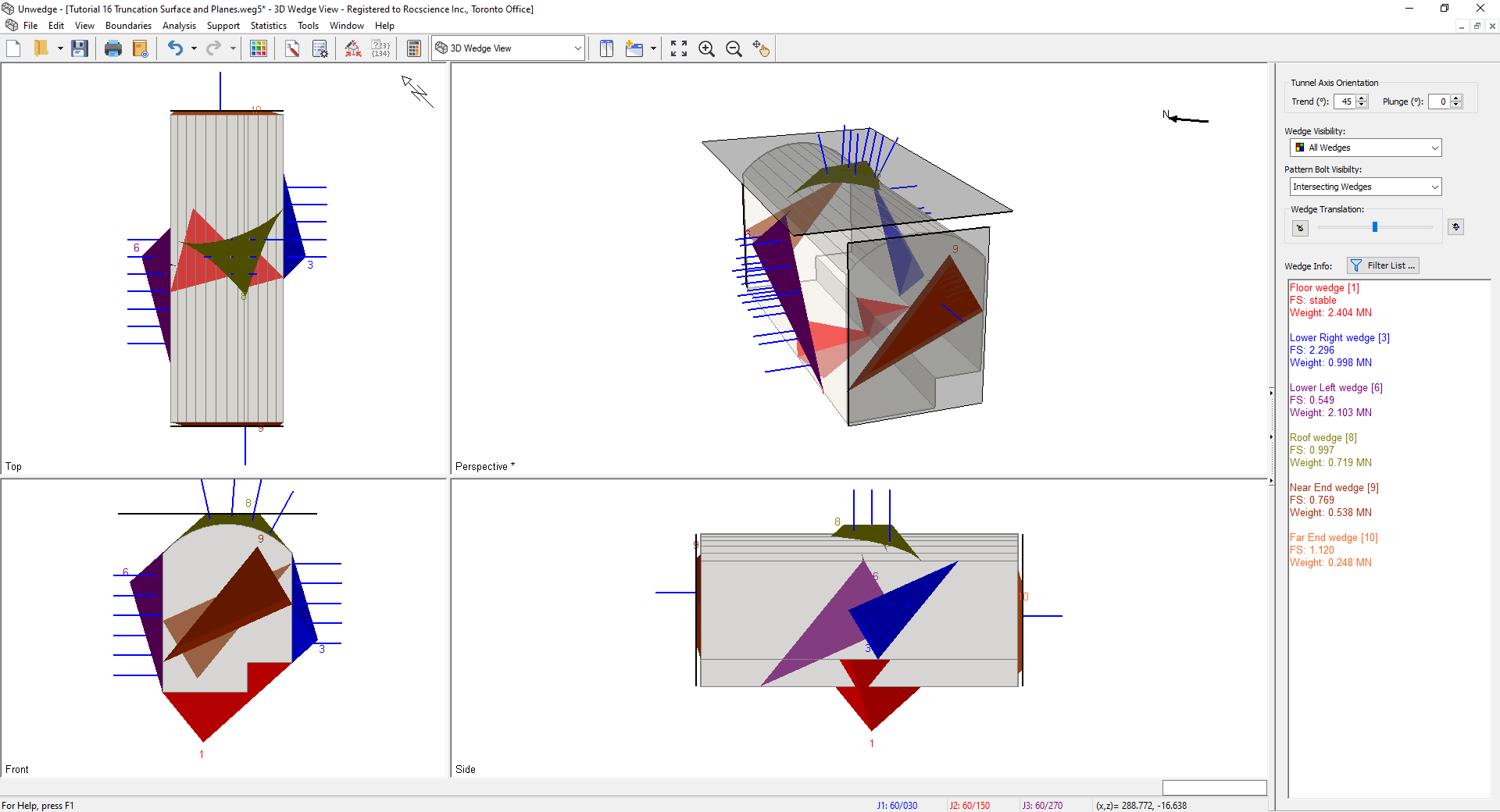
The End Wedges, "Near End Wedge [9]" and "Far End Wedge [10]" have been truncated 0.5 m from the tunnel opening by the End Truncation Planes. The wedge volume, weight, joint areas, associated forces and Factor of Safety are affected by the truncation (same as perimeter truncation). Likewise, to perimeter truncation, the bolt intersections are also affected.
Truncation in UnWedge is or limiting out-of-tunnel wedge extents (which would not be otherwise possible with the wedge geometry formed by three joint planes) while allowing bolts to pass through,
This concludes the tutorial.