6 - Intersecting Tunnels
1.0 Introduction
UnWedge is generally used to examine the safety of a single tunnel. However, it is possible to simulate two or more intersecting tunnels with a simple trick. This tutorial demonstrates how to model a drawpoint and adjacent drift in a hard rock mine. This junction is assumed to be a high-traffic area so support is applied to achieve a Design Factor of Safety of 2.0.
Topics Covered in this Tutorial:
- Tunnel Intersection
- Import DXF
- Scale Wedge Size
- Cable Bolt Support
- End Wedges
- End Wedge Support
- Spot Bolts
- Pattern Bolts
- Design Factor of Safety
Finished Product:
The finished tutorial can be found in the Tutorial 06 Intersecting Tunnels.weg5 file located in the Examples > Tutorials folder in your UnWedge installation folder.
2.0 Model
- If you have not already done so, run the UnWedge program by double-clicking the UnWedge icon in your installation folder or by selecting Programs > Rocscience > UnWedge > UnWedge in the Windows Start menu. When the program starts, a default model is automatically created.
If the UnWedge application window is not already maximized, maximize it now so that the full screen is available for viewing the model.
2.1 PROJECT SETTINGS
Let's start by configuring basic parameters in the Project Settings dialog.
- Select Projects Settings
 on the toolbar or the Analysis menu.
 - In the General tab, make sure Units = Metric, stress as MPa.
- Make sure Analysis Type = Deterministic and that the Compute End Wedges checkbox is selected.
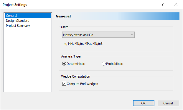
Project Settings Dialog - Select OK.
2.2 IMPORT DXF FILE
For this tutorial, we'll read in an AutoCAD DXF file that contains the geometry of the intersecting tunnels.
- Select File > Import > Import DXF
 .
. - Navigate to the Examples > Tutorials folder in your UnWedge installation folder and open the Tutorial 06 Drawplan.dxf file.
- In the Import DXF dialog, leave the default settings.
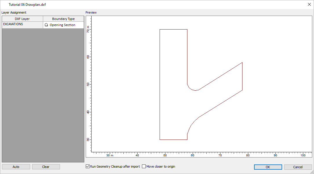
Tutorial 06 Drawplan Import Screen - Select OK.
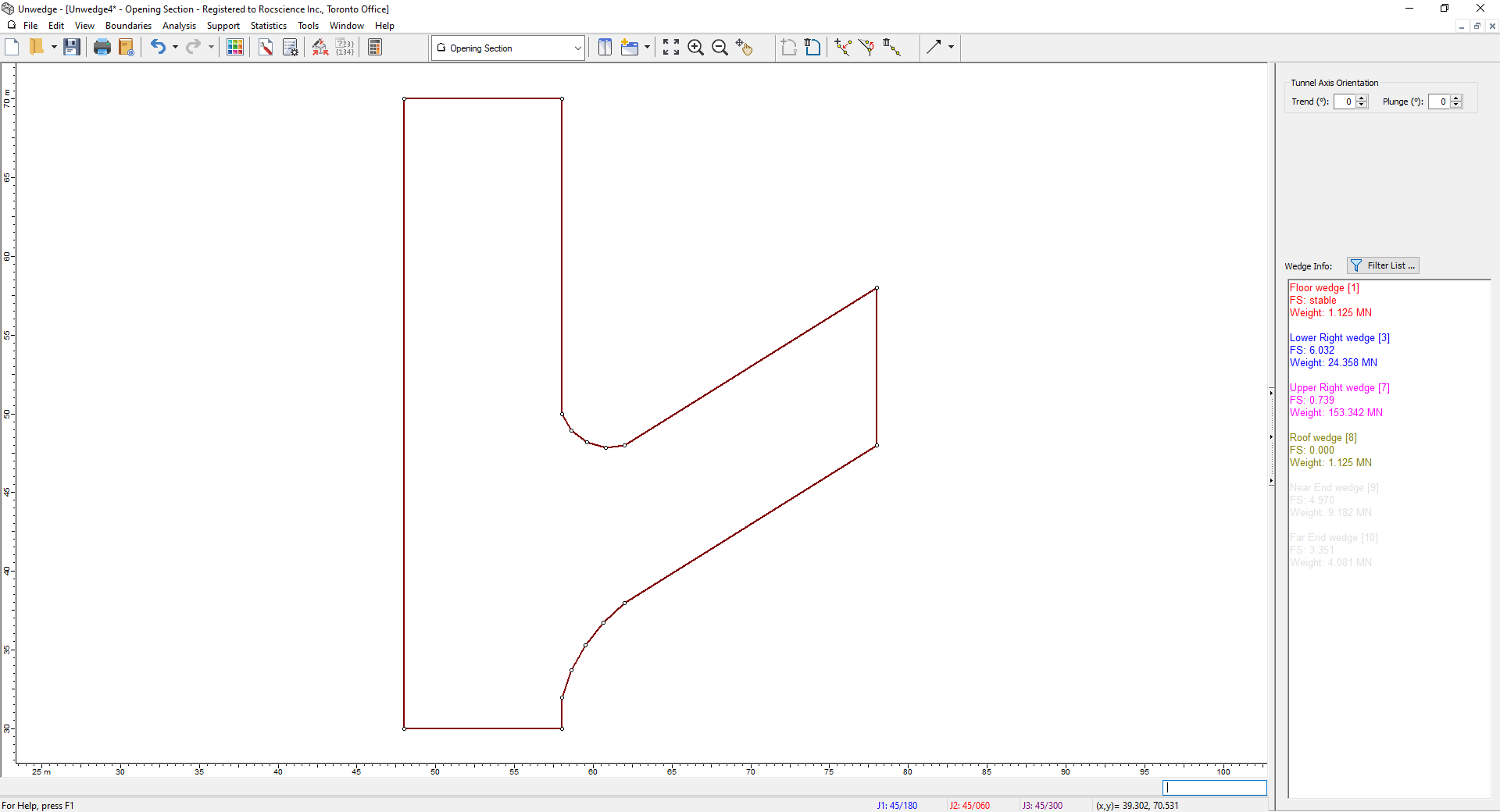
The model should appear as follows:
2.3 TUNNEL ORIENTATION
As you can see, by default, UnWedge assumes that the tunnel is horizontal. Since we have imported a plan view, we need to rotate the tunnel 90°.
- Switch to the 3D Wedge View
 by selecting it in the View dropdown on the toolbar or by selecting View > Select View > 3D Wedge View.
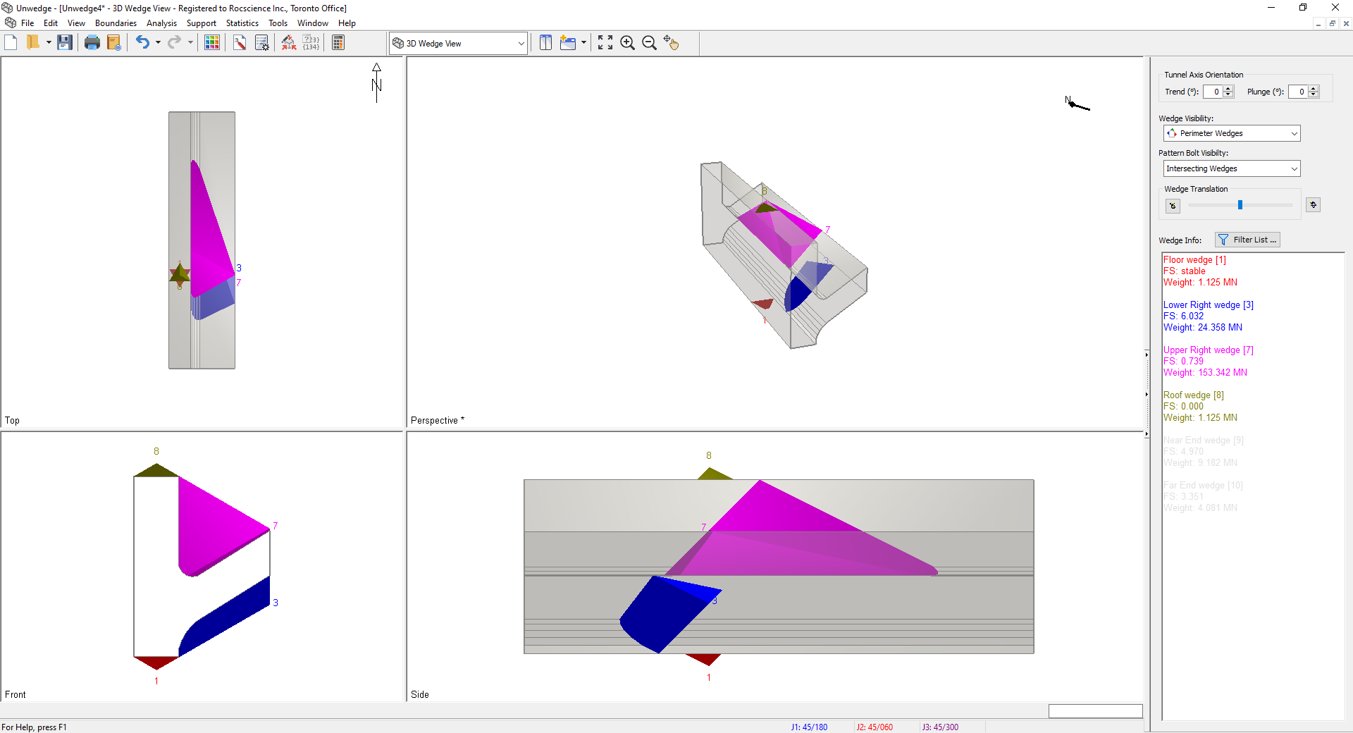
3D Wedge Model View - Under Tunnel Axis Orientation on the Sidebar, set the Plunge to 90°.
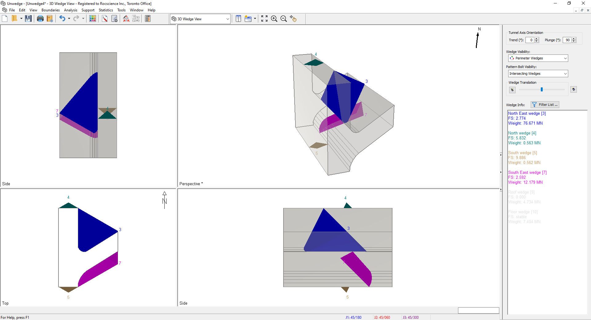
3D Wedge Model View
You will now see the two tunnels oriented such that the main drift is heading North. Notice that the perspective on the bottom left corner has changed from Front to Top. If your actual tunnel is heading in a different direction, you must change the Trend. For example, to set the main drift heading East set the Trend to 90°.
For this tutorial, we will assume that the main tunnel is heading North, so leave the Trend = 0°. You will now see the correct 3D representation of the tunnels. The geometry will be clearer if you rotate the Perspective view approximately 90° as shown. Alternatively, select the Reset Tunnel Rotation ![]() button from the sidebar or from the right-click menu in the Perspective view.
button from the sidebar or from the right-click menu in the Perspective view.
The height of the tunnel appears significantly too large. This will be addressed later by using the Tunnel Length function.
2.4 INPUT DATA
Next, we'll enter parameter data using the Input Data dialog.
- Select Input Data
 on the toolbar or the Analysis menu.
 - In the General tab, set Design Factor of Safety = 2.0.
Since miners are constantly at work in this area of the mine, we want a high Factor of Safety.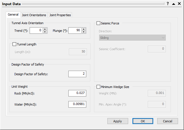
Input Data Dialog - Select the Joint Orientations tab.
By default, three Joint Orientations are already defined. - Enter the Dip and Dip Directions for the Joints as shown.
Joint 1: Dip = 69.67 degrees, Dip Direction = 36.41 degrees.
Joint 2: Dip = 84.53 degrees, Dip Direction = 143.55 degrees.
Joint 3: Dip = 48.13 degrees, Dip Direction = 262.1 degrees.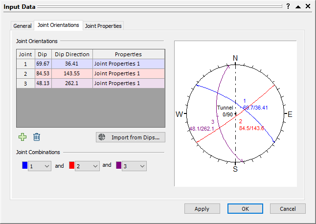
Input Data Dialog - Select the Joint Properties tab.
- For Joint Properties 1, enter Phi = 30 and Cohesion = 0.
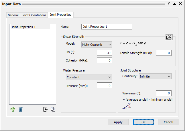
Input Data Dialog
Note that all three Joint Orientations are assigned these properties by default. - Select Apply.
Notice the height of tunnel is extremely disproportionate. We will use the Tunnel Length function to enter the actual tunnel height.
2.5 TUNNEL LENGTH
- Click on the General tab.
Let’s assume that the height of the tunnel is 5 m. - Select the Tunnel Length checkbox and set Length = 5 m.
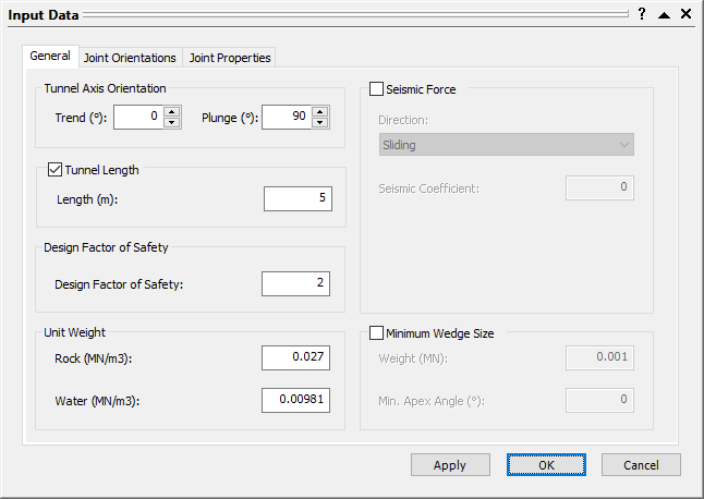
Input Data Dialog - Select OK.
Now you can see that the wedges have a maximum height of 5 m. Your screen should now look like this:
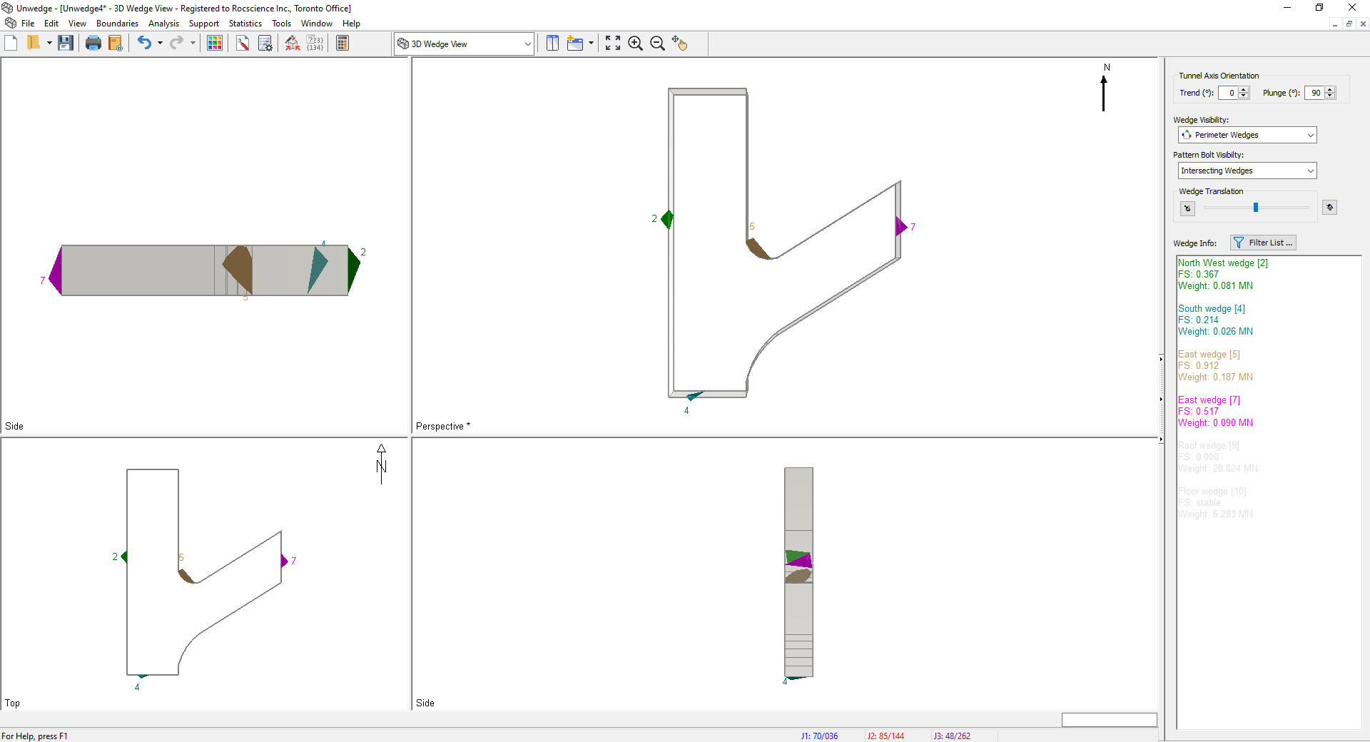
3.0 Perimeter Wedge Support
You will see in the Sidebar that all of the wedges have a Factor of Safety below 1. Recall that we want a Factor of Safety of at least 2. This can be easily accomplished by adding a few Spot Bolts. We will support the Perimeter Wedges using cable bolts.
- Switch to the Perimeter Support Designer
 view by selecting it from the View dropdown on the toolbar or the View > Select View menu.
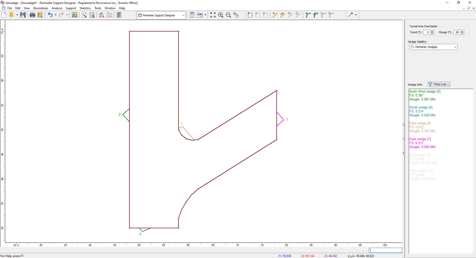
Perimeter Support Designer Model View - Select Bolt Properties
 on the toolbar or the Support menu.
 - In the Bolt Properties dialog:
- Change Bolt Property 1 Type = Cable Bolt.
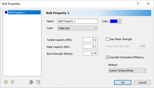
Bolt Properties Dialog - Select OK.
- Select Add Spot Bolt
 on the toolbar or Support menu.
 - In the Add Spot Bolt dialog:
- Leave Bolt Properties selected as Bolt Property 1.
- Leave Bolt Length = 2 m.
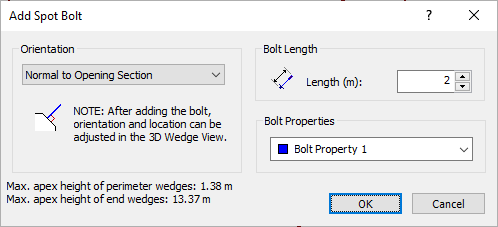
The maximum apex height for the Perimeter Wedges is less than 1.5 meters so the default 2-meter bolts should be sufficient.
- Select OK.
- Click on the perimeter of the model such that the bolt goes through one of the wedges.
- Repeat these steps until Wedge 5 and 7 are supported by one bolt and Wedge 2 and Wedge 4 are supported by two bolts.
The screen should look like this:
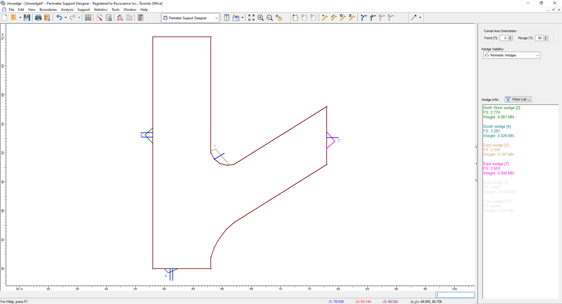
You can see in the Sidebar that the Factor of Safety for all Perimeter Wedges is now greater than 2, thus achieving the Design Factor of Safety.
4.0 Roof Wedges
4.1 VIEW END WEDGES
To see the wedges that form at the top and bottom of the tunnel intersection, we need to look at the End Wedges.
- Switch to the End Wedges
 view using the drop-down menu on the toolbar or from the menu View > Select View.
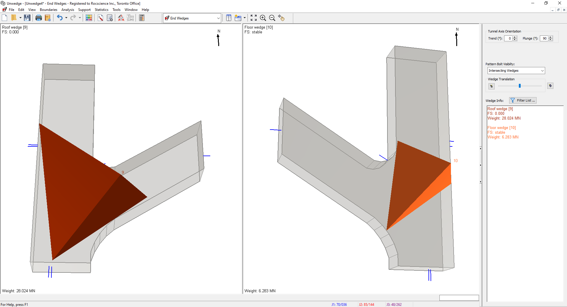
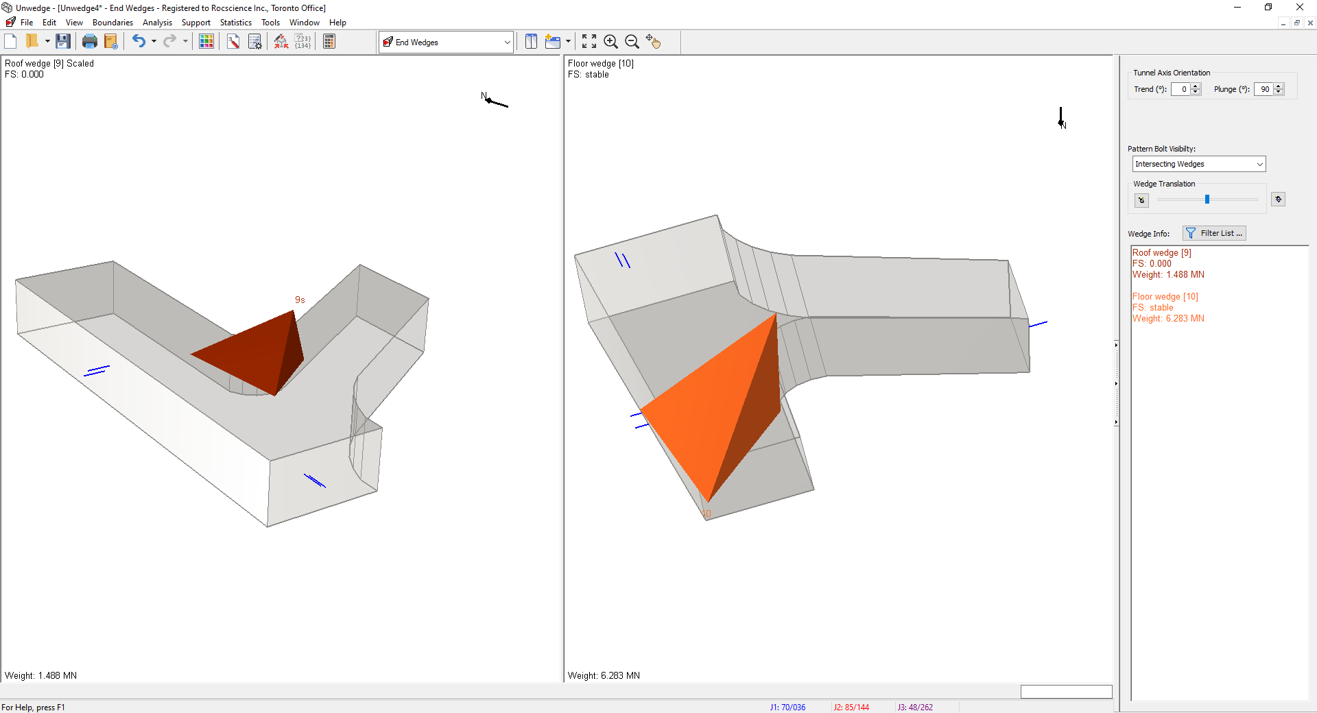
End Wedge Model View - You can rotate the views to get a realistic view of the roof and floor wedges like this:
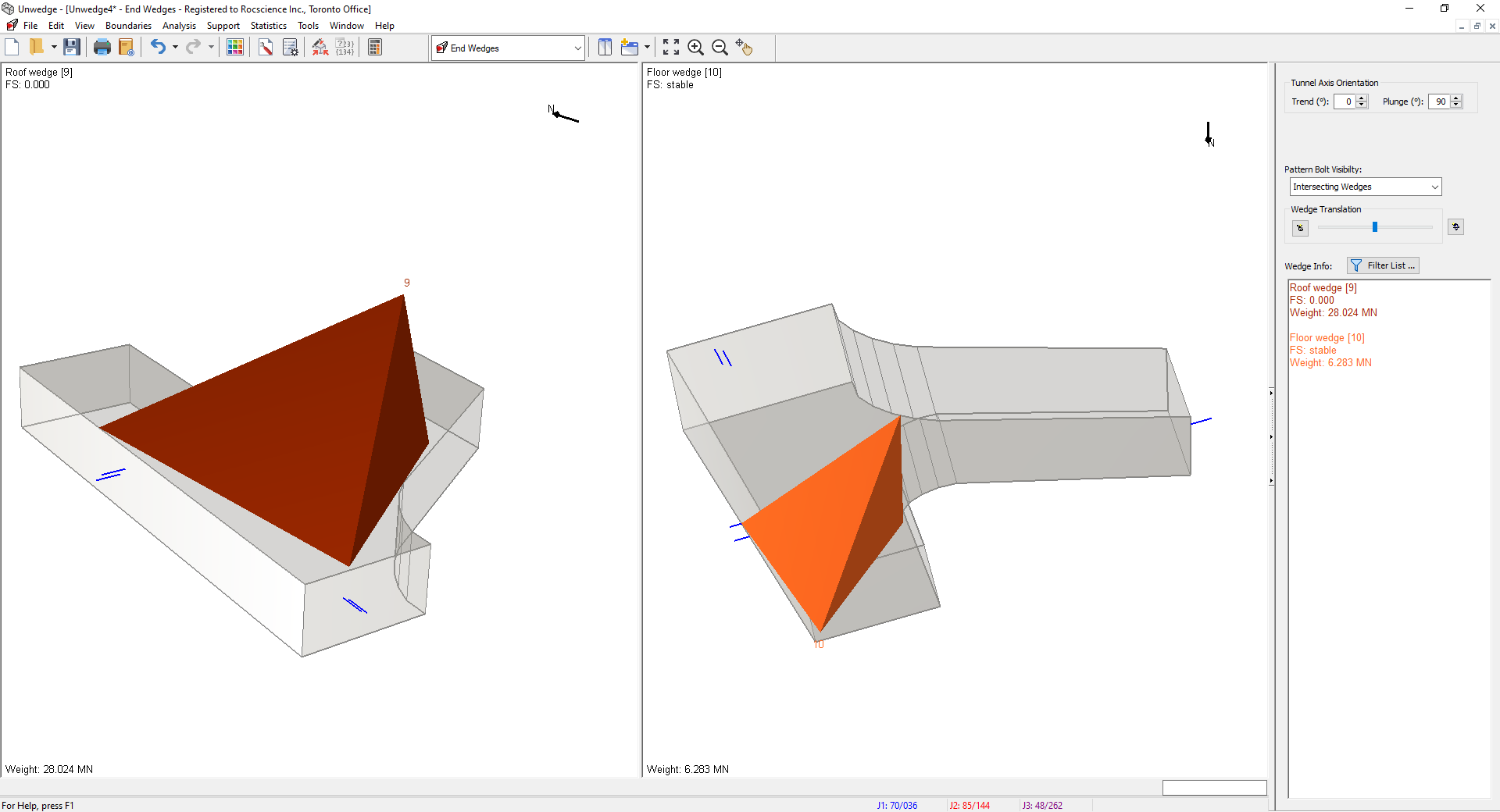
End Wedge Model View
The maximum wedge found in the roof of the excavation is very large with an Apex Height of approximately 13 m and a Weight of almost 30 MN. However, the largest trace length actually observed underground was 10 m in length so we can scale the wedge to reflect this.
4.2 SCALE WEDGE TO ROOF
- Select Scale Wedges
 on the Analysis menu.
The Scale Wedges dialog appears.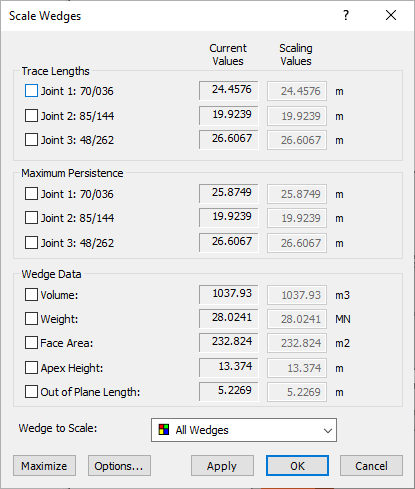
- At the bottom of the dialog, set Wedge to Scale = Roof.
- Under Trace Lengths, select all three joints and set Scaling Values = 10 m for all three.
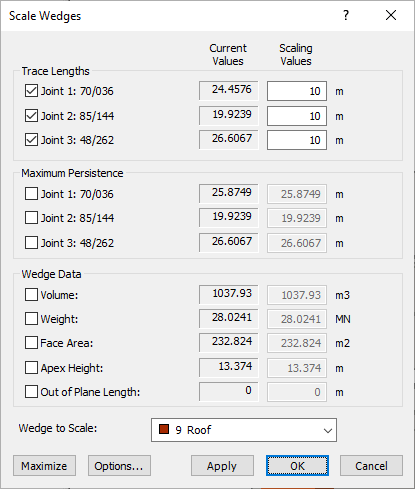
- Select OK.
You will now see that the Roof Wedge is now ~ 1.5 MN. This can be supported by shotcrete or cable bolts. Using the default shotcrete, the layer of shotcrete would have to be 40 cm thick to support the wedge with a factor of safety of 2, which is required because the drawpoint and drift are commonly travelled working areas and must be safe. Alternatively, the wedge could be supported with a pattern of 8 meters long, end-plated cable bolts installed at 1.3 meters by 1.3 meters centred. We will choose the cable bolt support option.
4.3 ADD BOLT PATTERN
We will support the roof wedge using the same cable bolts as used for the Perimeter Wedges so there is no need to change the Bolt Properties. We will add an array of bolts using the Add Bolt Pattern option.
- Switch to the End Support Designer
 view by selecting it on the toolbar or the View > Select View menu.
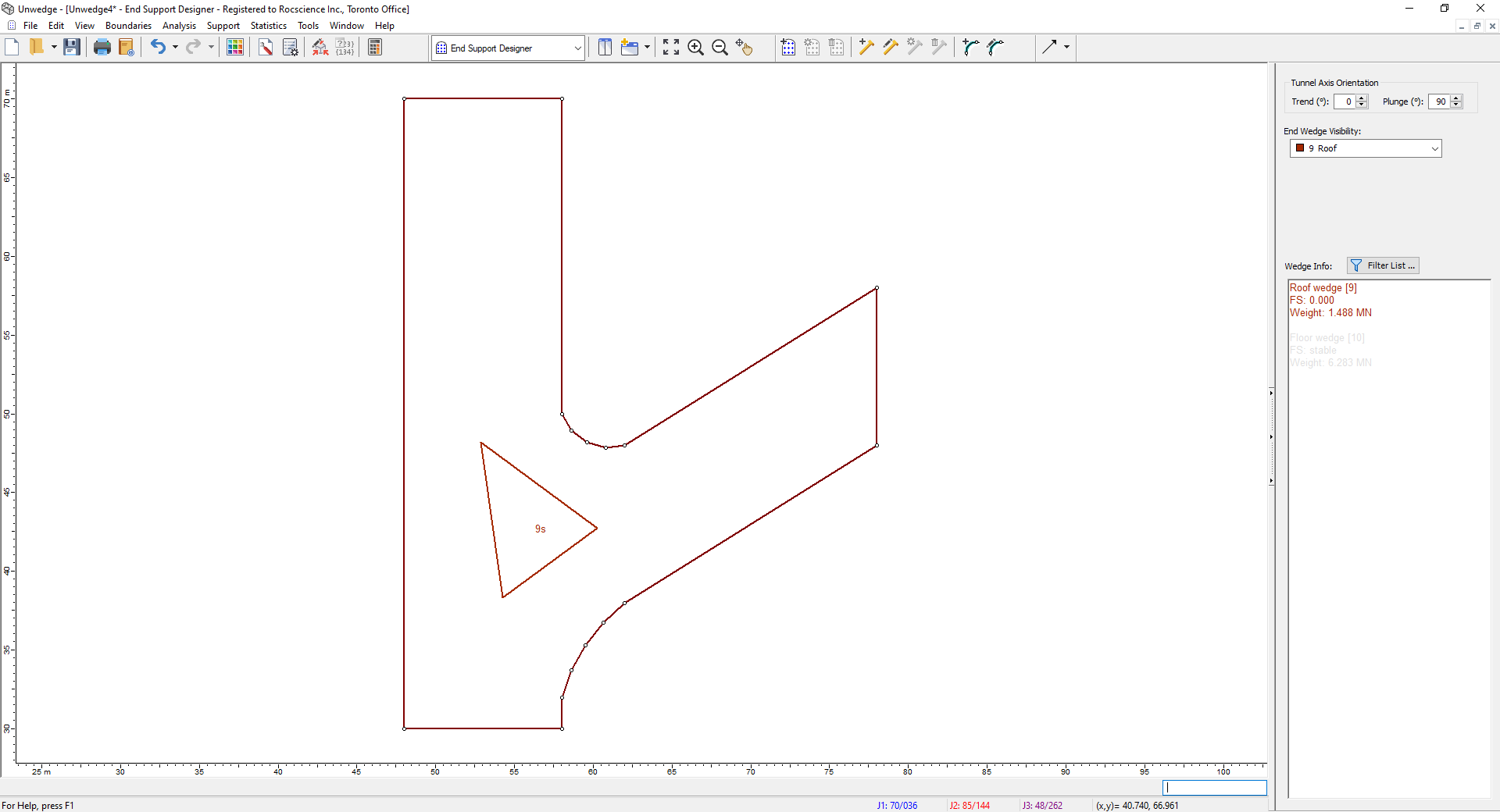
End Support Designer Model View - Make sure End Wedge Visibility on the Sidebar is set to Roof.
- Select Add Bolt Pattern
 on the toolbar or the Support menu.
 - In the Add Bolt Pattern on Ends dialog:
- Set Bolt Length = 8.
- Set Apply to End = Near End Only. This will apply the Bolt Pattern to the Roof wedge only. No supports are required for the Floor wedge since it is stable.
- Under Pattern Spacing, set Horizontal = 1.3 m.
- Under Pattern Spacing, set Vertical = 1.3 m.
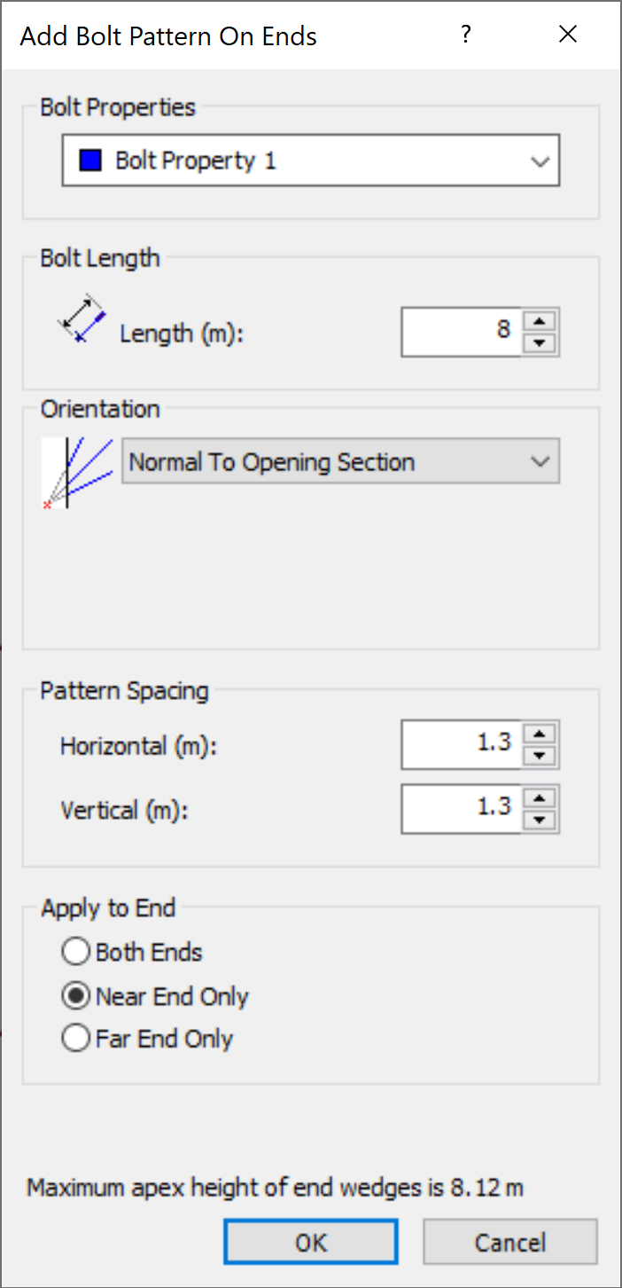
Note that the maximum apex height of End Wedges may be greater than 8 m. However, this maximum is for the floor wedge, which we do not care about. Therefore 8 m long bolts are fine.
- Select OK.
- You will now see an array of cable bolt locations. Click on the top-left corner of the Opening Section to place the array.
Your screen should now look like this:
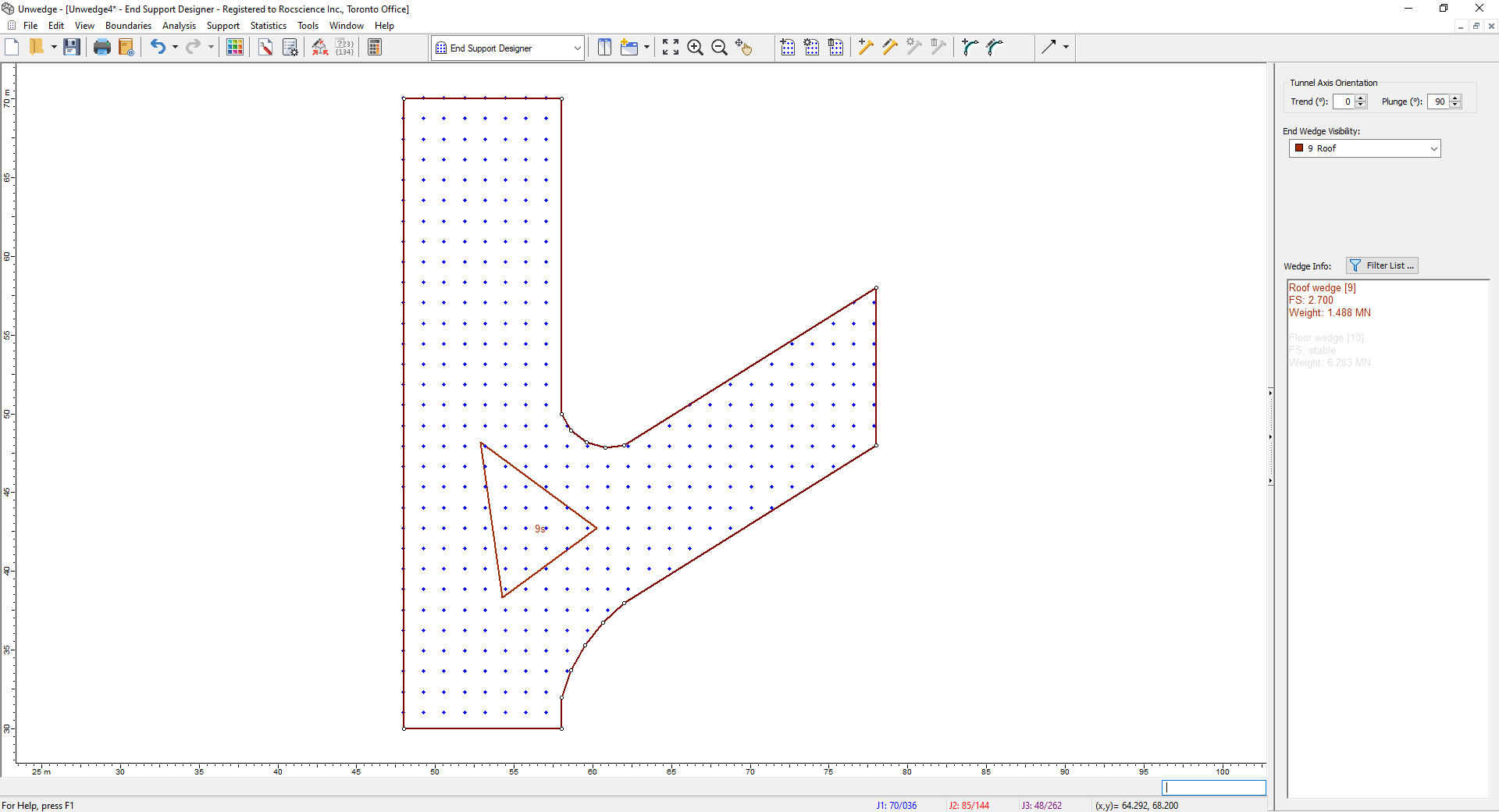
You can see in the Sidebar that the Factor of Safety for the Roof wedge is now greater than 2.
5.0 3D Wedge Views
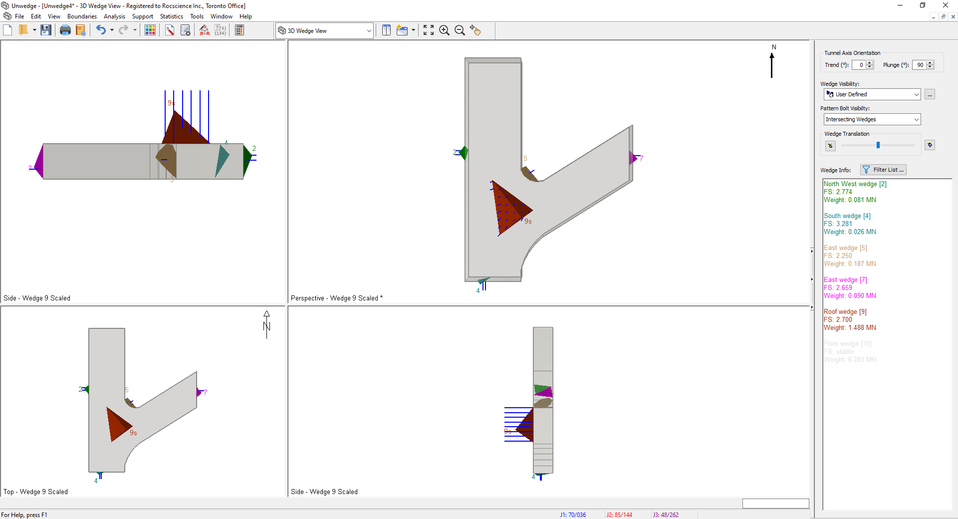
- Return to the 3D Wedge View by selecting it in the View dropdown on the toolbar.
- Turn off the visibility of the Floor wedge by:
- In the Sidebar Wedge Visibility dropdown, select User Defined.
- Click the
 button next to the dropdown.
The Select Visible Wedges dialog appears. - Uncheck 10 Floor.
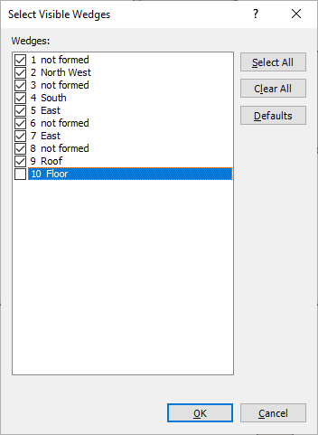
- Select OK.
The screen should now look like this:
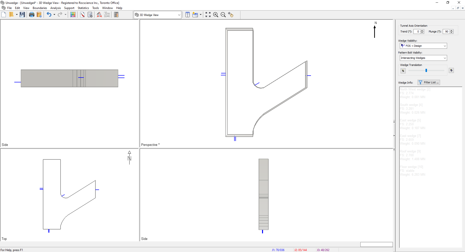
To check that all wedges are within the Design Factor of Safety, set Wedge Visibility on the Sidebar to FOS < Design.
You should now see no wedges.
This concludes the tutorial. You are now ready for the next tutorial, Tutorial 07 - Probabilistic Analysis in UnWedge.