4 - Joint Combinations
1.0 Introduction
This tutorial demonstrates the Joint Combinations option in UnWedge. It is inherent in the UnWedge analysis that wedges can only be formed by the intersection of three joint orientations. UnWedge does NOT consider more than three joint planes simultaneously in the analysis. However, if your Input Data includes more than three possible joint orientations, the Joint Combinations option allows you to select and analyze different combinations of three joints. The selection of combinations can be done manually or the Combination Analyzer can be used to help you automatically determine which are the most critical combinations of joints to analyze.
Topics Covered in this Tutorial:
- Import DXF
- Joint Combinations
- Combination Analyzer
- Required Support Pressure
- Design Factor of Safety
- Adding Support Pressure
- Passive / Active Support Force
Finished Product:
The finished tutorial can be found in the Tutorial 04 Joint Combinations.weg5 file located in the Examples > Tutorials folder in your UnWedge installation folder.
2.0 Model
- If you have not already done so, run the UnWedge program by double-clicking the UnWedge icon in your installation folder or by selecting Programs > Rocscience > UnWedge > UnWedge in the Windows Start menu. When the program starts, a default model is automatically created.
If the UnWedge application window is not already maximized, maximize it now so that the full screen is available for viewing the model.
2.1 PROJECT SETTINGS
Before we start, we'll make sure Project Settings are the way we want them.
- Select Project Settings
 from the toolbar or the Analysis menu.
 - In the General tab, make sure Units = Metric, stress as MPa.
- Set the Analysis Type = Deterministic.
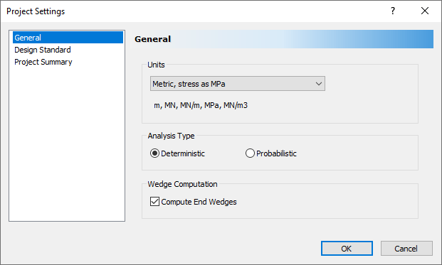
Project Settings Dialog - Select OK.
2.2 IMPORT DXF FILE
For this tutorial, we will start by reading in a DXF file that contains the coordinates of the Opening Section boundary. When you import the file, you're given the option of defining the boundary type you are about to import. DXF files can also be imported into UnWedge as Ground Surface. They can also be imported as Polyline Tools or Polygon Tools. These are the same tools available in the Tools menu of UnWedge; once imported, they can be used as guides for creating the geometry, for example.
- Select File > Import > Import DXF

- Navigate to the Examples > Tutorials folder in your UnWedge installation folder and open the Tutorial 04 Tunnel Boundary.dxf file.
In the import dialog, you're given the option of defining the Boundary Type.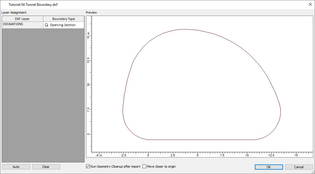
Tunnel Boundary Dialog - Leave the default selection of Boundary Type = Opening Section.
- Select OK.
The Opening Section is created from the .DXF.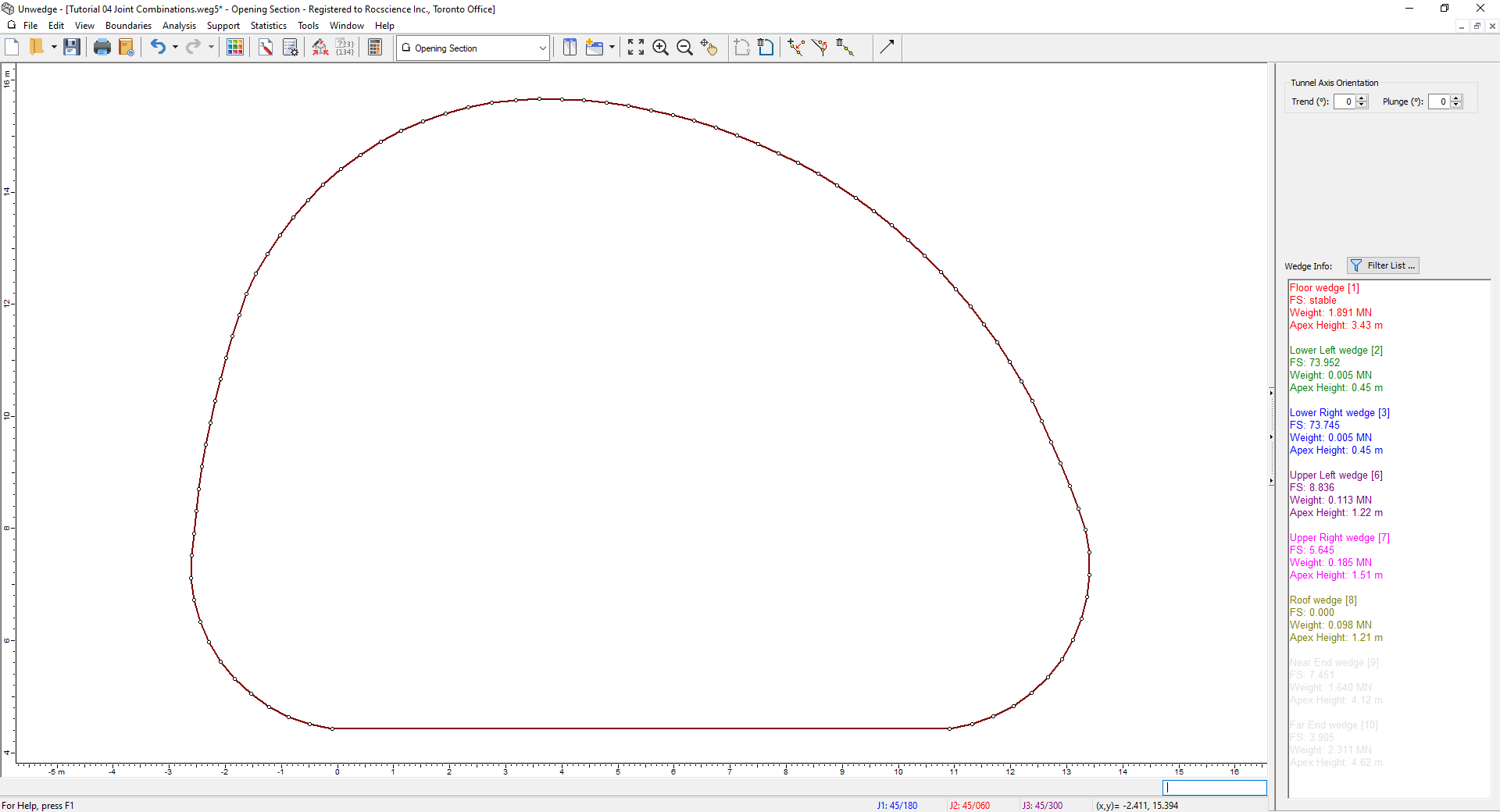
Open Section Model View - Switch to the 3D Wedge View
 by selecting it in the View dropdown on the toolbar.
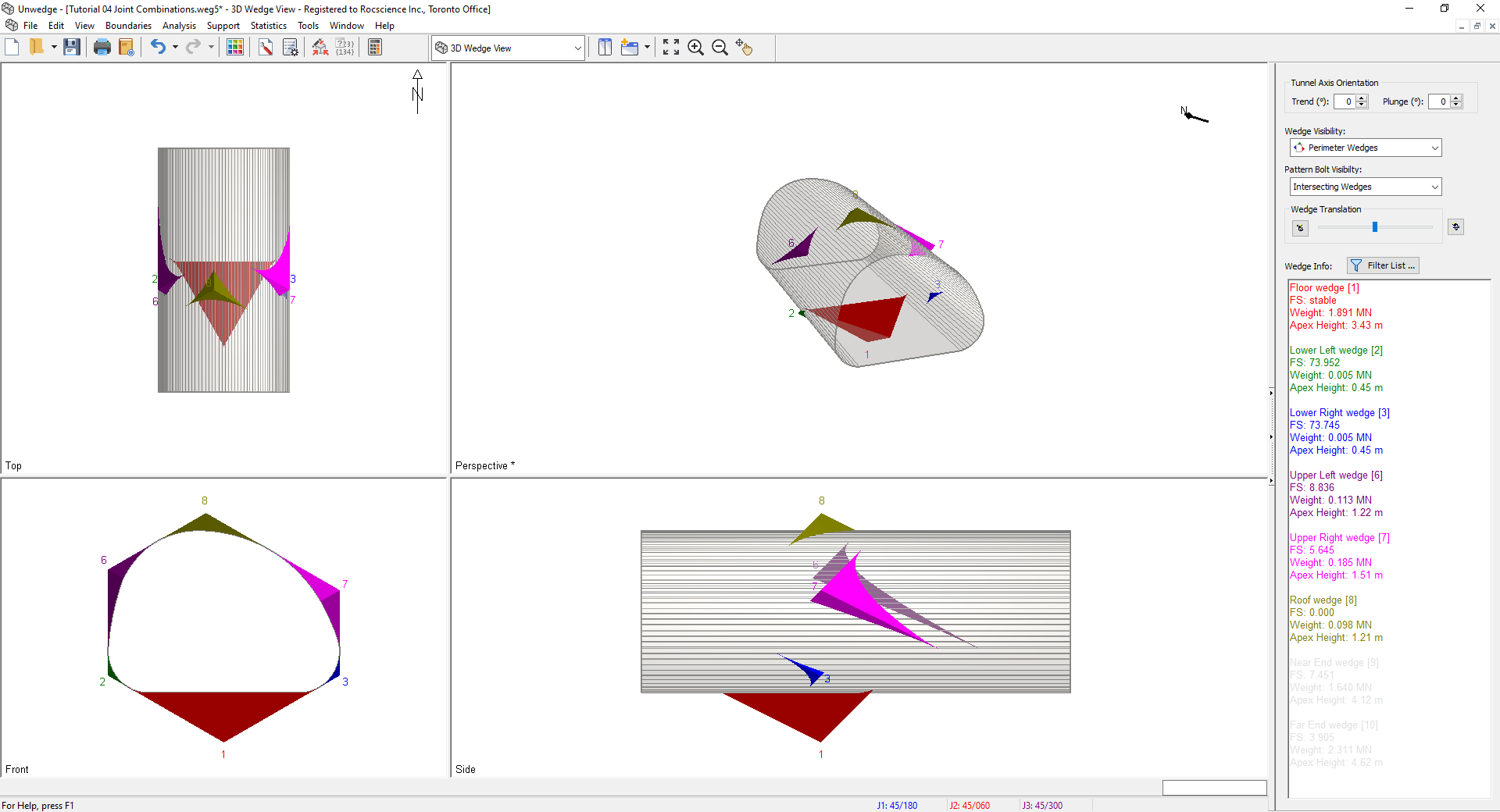
3D Wedge Model View
2.3 INPUT DATA
Now let’s define the tunnel and joint properties in the Input Data dialog.
- Select Input Data
 on the toolbar or the Analysis menu.
 - In the General tab under Tunnel Axis Orientation, set Tunnel Trend = 60, Plunge = 0.
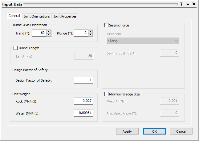
The Design Factor of Safety (= 1 by default).We will be discussing this later in the tutorial. - Select the Joint Orientations tab.
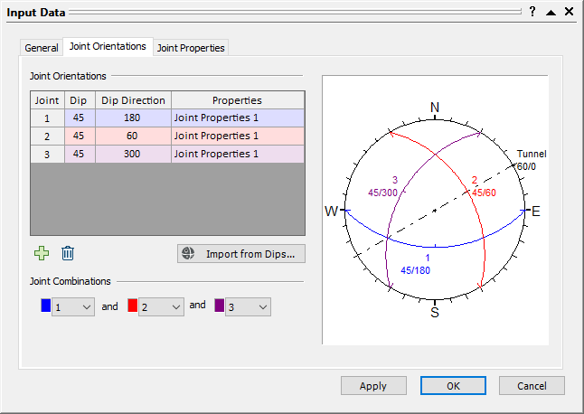
Input Data Dialog
By default, three Joint Orientations are already defined. - Keep the three default Joint Orientations.
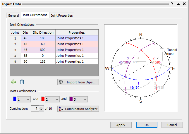
- Click the Add
 button twice to add two more Joint Orientations.
 - For Joint 4, set Dip = 65 and Dip Direction = 0 .
- For Joint 5, set Dip = 30 and Dip Direction = 35.
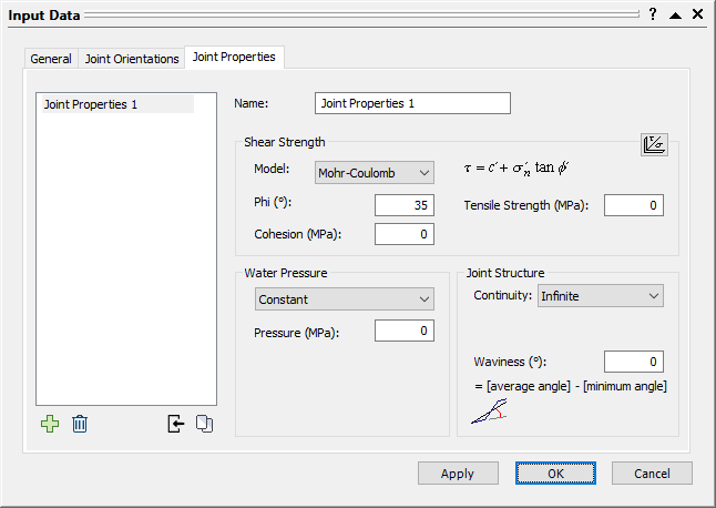
Input Data Dialog - Select the Joint Properties tab.
- Set Phi = 35 and Cohesion = 0 for the default joint property type ( Joint Properties 1).
Input Data Dialog - Go back to the Joint Orientations tab and note that Joint Properties 1 is assigned to all five Joints (i.e., all joints are assumed to have the same Shear Strength properties).
- Also, note the Joint Combinations option below the list of Joint Orientations.
Since we have more than three joint orientations defined, the Joint Combinations option allows you to select which combination of three joints will be used for the UnWedge analysis
You can manually cycle through all possible combinations of three joints by manually selecting them in the Joint Combinations control or you can analyze all possible joint combinations with the Combination Analyzer option. We will look at both options.
2.4 MANUAL SELECTION OF JOINT COMBINATIONS
You can manually cycle through all possible combinations of three joints by clicking on the Joint Combinations control. Each time you click on the up / down arrow buttons, a new joint combination is selected. Since we have five possible joints, this results in 10 possible combinations of three different joints.
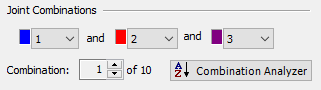
- Click on the Up arrow of the Joint Combinations control.
- Each time you click, a different combination of three joints is selected as indicated by the Combination box and the Stereonet at the right of the dialog.
- The currently selected Joint Orientations (great circles) are highlighted in colour on the Stereonet. Joint Orientations that are currently NOT used are displayed in grey.
- Drag the Input Data dialog over to the side of the screen so that you can see the full 3D Wedge View.
- Click through all 10 joint combinations and observe the different wedges that are formed in the view.
A great variety of different sizes and shapes of wedges can be formed from the 10 joint combinations.The displayed length of the tunnel automatically changes according to the size and orientation of the wedges that are formed. - As you click through the combinations, note that the analysis results for the currently selected combination (Factor of Safety, Wedge Weight, etc.) are displayed in the Wedge Info panel in the Sidebar
TIP: The display of unused joints on the Stereonet View can be turned on/off in the Display Options dialog under the General tab by selecting/deselecting the Show Unused Joints on Stereonet checkbox.
The manual selection and analysis of joint combinations is of limited practical usefulness if you have more than four or five Joint Orientations. Therefore we will now look at the Combination Analyzer option, which automates the process of analyzing multiple joint combinations.
3.0 Combination Analyzer
The Joint Combination Analyzer allows you to automatically carry out the UnWedge analysis on all possible combinations of three joints if your input data includes more than three possible joint planes. A summary of analysis results can then be viewed, which allows you to quickly determine which combination of three joints is the most critical (i.e., you can sort results according to Maximum Required Support Pressure, Factor of Safety, Wedge Weight, etc).
3.1 USING THE JOINT COMBINATION ANALYZER
- Select the Combination Analyzer
 button in the Input Data dialog (or you can select Combination Analyzer
  from the toolbar or the Analysis menu).
The Combination Analyzer dialog appears.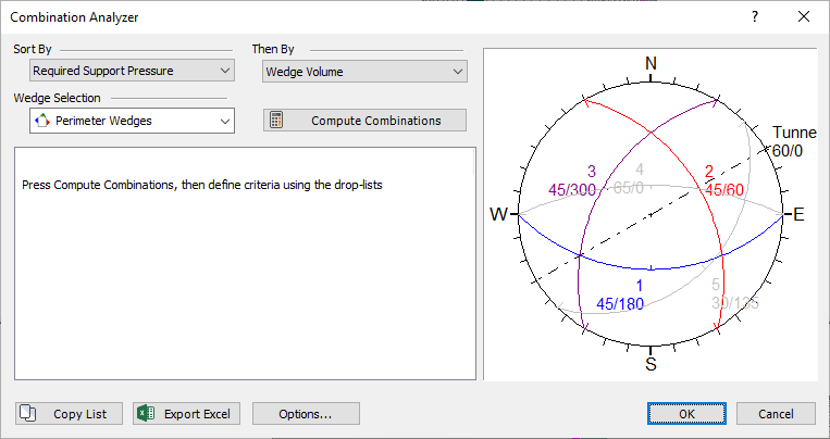
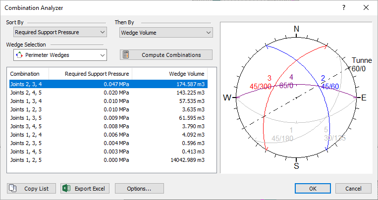
Combination Analyzer Dialog - Select Required Support Pressure in the Sort By dropdown and Wedge Volume in the Then By dropdown.
- Click the Compute Combinations
 button in the dialog to compute the UnWedge analysis for all possible combinations of three joints.
A summary of results is displayed in the dialog. The results can be sorted according to Required Support Pressure, Factor of Safety, Wedge Volume, etc, by selecting the desired parameters from the two dropdowns at the top of the dialog. We will discuss the significance of Required Support Pressure in the next section. The Sort By dropdown is the first sorting criteria and the Then By dropdown is the second sorting criterium (if identical results are encountered with the primary sorting).
You should see the following results.
Combination Analyzer Dialog
Results are always sorted from “most critical” to “least critical.” For example, the first joint combination in the list always represents the highest support pressure, the largest wedge volume or weight, the lowest Factor of Safety, etc., according to the primary sorting criterion.
You can also filter the results with the Wedge Selection dropdown. You can choose Perimeter Wedges, End Wedges, All Wedges, or any individual wedge (e.g., Roof Wedge). Note that, when the Wedge Selection represents multiple wedges (e.g., Perimeter Wedges), the displayed results represent the most critical wedge for each joint combination. - Experiment with the sorting and Wedge Selection parameters, and observe the listing of results. When you are finished, reset the sorting parameters to Required Support Pressure and Wedge Volume, and Wedge Selection to Perimeter Wedges.
Based on these sorting criteria, the most critical wedge is produced by Joint Combination 2, 3, 4, with a Required Support Pressure = 0.047 MPa and a Wedge Volume = 174.587 m3. - Click on Combination 2, 3, 4 at the top of the results list.
Combination Analyzer Dialog - Select OK.
The wedges for Joint Combination 2,3,4 are now displayed in the 3D Wedge View. - Select the Filter List
 button in the Wedge Info panel in the Sidebar.
 - In the Wedge Information Filter dialog, select the Defaults button and then select the checkboxes for Wedge Volume and Support Pressure.
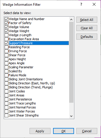
- Select OK.
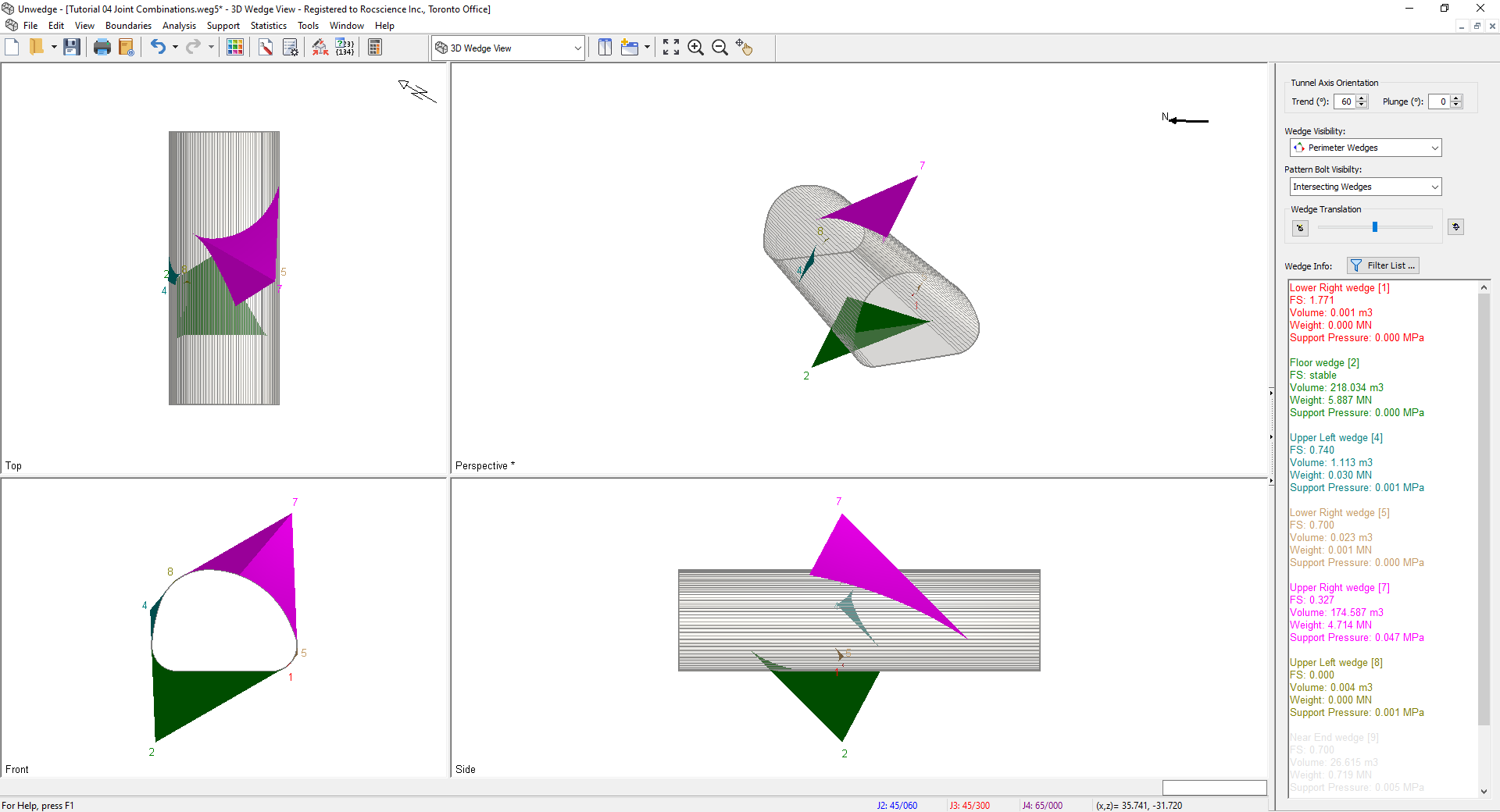
Look at the results for the Upper Right Wedge (wedge #7) in the Wedge Info panel.
This is the most critical wedge determined by the Combination Analyzer. Notice the Support Pressure (0.047 MPa) and Wedge Volume (175 m 3) correspond to the results computed in the Combination Analyzer dialog. Also, notice that the Support Pressure for all other wedges is less than the Required Support Pressure for wedge #7.
3.2 REQUIRED SUPPORT PRESSURE
The Required Support Pressure is the uniform support pressure applied normal to the excavation boundary that would be required to achieve the Design Factor of Safety for a particular wedge.
Notes:
- If the Factor of Safety of a wedge is already greater than the Design Factor of Safety, the Required Support Pressure is zero.
- The Design Factor of Safety is entered in the Input Data dialog under the General tab. For this tutorial, we are using the default value of Design Factor of Safety = 1.
We will now verify the relationship between the Required Support Pressure calculated by UnWedge and the Design Factor of Safety by applying a Support Pressure to the excavation boundary.
- Switch to the Perimeter Support Designer
 viewby selecting it in the View dropdown on the toolbar.
 - Before we add the Support Pressure, notice that the current Factor of Safety of the Upper Right Wedge is 0.327, as displayed in the Wedge Info panel.
- Select Support > Add Pressure
 .
.
The Add Pressure On Perimeter dialog appears.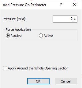
- Set Pressure = 0.047 MPa .
- Select the Apply Around the Whole Opening Section checkbox.
- Leave Force Application = Passive.
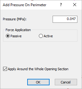
- Select OK.
Because we selected the Apply Around the Whole Opening Section checkbox, the Support Pressure is automatically applied to the entire perimeter of the opening section. Your screen should look as follows.
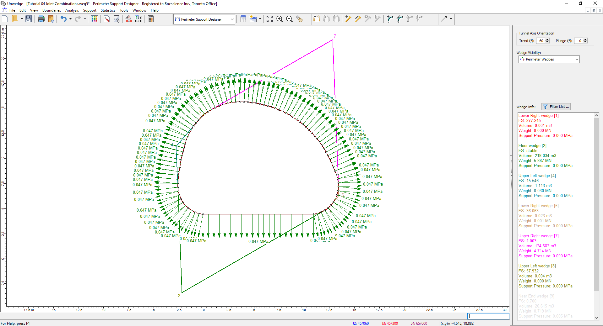
The support pressure is applied as a UNIFORM pressure, normal to each line segment of the opening section boundary.
Now observe the results in the Wedge Info panel:
- The Factor of Safety for the Upper Right Wedge = 1.003, which is approximately equal to the Design Factor of Safety. Because we applied the Required Support Pressure calculated for the unsupported wedge, the actual Factor of Safety is now equal to the Design Factor of Safety.
- The Required Support Pressure for the Upper Right Wedge is now zero since no further support pressure is required to achieve the Design Factor of Safety.
- Because we applied the support pressure to the entire Opening Section boundary, the Factor of Safety for all other wedges is greater than the Design Factor of Safety. In general, if you apply the Required Support Pressure for the most critical wedge, all other wedges will have a Factor of Safety GREATER THAN the Design Factor of Safety.
The Required Support Pressure can be used as a starting point for the design of the actual support system (e.g., bolts and shotcrete). For example, it can help you to estimate bolt capacity, length, and pattern spacing. In any case, it will take some trial and error to design the actual support system to achieve the Design Factor of Safety for all wedges.
Now we will demonstrate that, by applying the Required Support Pressure for the most critical joint combination, the Factor of Safety for all wedges produced by all joint combinations is greater than the Design Factor of Safety. Return to the Combination Analyzer.
- Select Analysis > Combination Analyzer to return to the Joint Combination Analyzer.
- Select Factor of Safety as the primary sorting criterion ( Sort By) and Required Support Pressure as the secondary sorting criterion ( Then By).
- Click the Compute Combinations button.
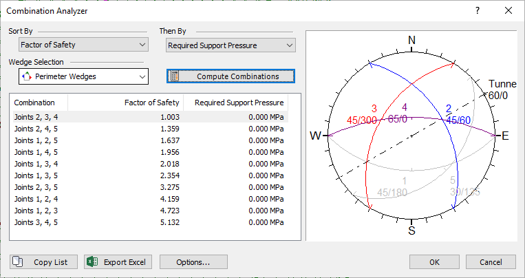
Combination Analyzer Dialog - Select OK.
Notes:
- The lowest Factor of Safety is 1 for the most critical wedge of Joint Combination 2,3,4.
- All other Factor of Safety values (representing the most critical wedge for each joint combination) are GREATER THAN the Design Factor of Safety.
- In all cases, the Required Support Pressure is now zero.
This demonstrates that, by applying the Required Support Pressure for the most critical joint combination, all wedges for all joint combinations will have a Factor of Safety greater than (or equal to) the Design Factor of Safety.
3.3 PASSIVE OR ACTIVE SUPPORT FORCE APPLICATION
Finally, remember that we applied the Support Pressure as a Passive force (in the Add Pressure dialog). Passive force application means that the support force acts to increase the resisting forces that stabilize the wedge.
Notes:
- Required Support Pressure is calculated assuming a Passive force application.
- Bolts or shotcrete in UnWedge are always implemented as a Passive support force.
- It is also possible to apply an Active support pressure (by selecting Force Application = Active in the Add Pressure dialog). Active force application means that the support force acts to decrease the driving forces on the wedge.
In general, Passive support will always give a lower Factor of Safety than Active support and will therefore result in a more conservative estimate of support design requirements. For more information about Passive or Active force application, see Active / Passive Force Application in the UnWedge Theory Documents.
This concludes the tutorial. You are now ready for the next tutorial, Tutorial 05 - Field Stress in UnWedge.