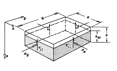
Lateral Stress Overview
Lateral Stress toggles between two options, Gravity and Constant.
- With the Gravity option, the user inputs locked in stress (lateral stress at the pillar surface) and horizontal / vertical stress ratios, from which the lateral stresses are calculated.
- With the Constant option, the user inputs the actual lateral effective stresses.
The corresponding options in the Input Data dialog will change as this option is toggled.
Locked In Stress
This is the lateral stress at the surface of the pillar. This value can be manipulated to represent preexisting stress conditions, or the effects of the overburden on the lateral stress.
Horizontal to Vertical Stress Ratios
Used with the Gravity lateral stress option.
Horizontal Effective Stresses
Used with the Constant lateral stress option.
Pillar Shape
Rectangular Pillar
For a Rectangular Pillar, the lateral stresses are given in the x and y directions.
Polygonal Pillar
For a Polygonal Pillar, the lateral stresses are given relative to Trend 3 (orientation of Sigma 3).
Stress Transformations
Vertical Abutments
For vertical abutments (i.e., Abutment Orientation Plunge = 90 degrees), the lateral stresses are always applied normal to the abutments (in the x and y directions). Therefore, the effective lateral stress = effective normal stress on the abutments.

Non-Vertical Abutments
For non-vertical abutments, the lateral stresses are not always applied normal to the abutments since the polygon segments can be oriented arbitrarily. In addition, the abutments may be non-vertical.
- The horizontal principal stresses, Sigma 1 and Sigma 3, are always horizontal and perpendicular to one another.
- The rotation of the horizontal principal stresses in the x-y plane is dictated by Trend 3 (measured clockwise from the y-axis (or North)).
A 2D stress transformation is applied to the horizontal principal stresses in order to obtain the horizontal stresses in the global x-y coordinates. For the case of non-vertical abutments, the vertical stress also impacts the normal stresses on the abutments. The vertical stress is calculated by the effective weight of everything above the midway height of the pillar. The normal stress takes into account the components of all the principle stresses which act normal to the abutment face.