6 - Reinforced Concrete Sections
1.0 Introduction
In this tutorial we'll explore the various options available in the Concrete Designer dialog. To begin, we'll first quickly set up the basics of the model, then specify the reinforced concrete section.
Topics Covered in this Tutorial:
- Concrete Designer
- Pile Properties
- Concrete Pile
Finished Product:
The finished product of this tutorial can be found in the Tutorial 6 – Reinforced Concrete Sections.rspile2 data file. All tutorial files installed with RSPile can be accessed by selecting File > Recent Folders > Tutorials Folder from the RSPile main menu.
2.0 Setting up the initial model
2.1 Project Settings
- Go to Home > Project Settings

- In the General tab ensure Units = USCS (Imperial) and Program Mode Selection = Pile Analysis.
- In the Pile Analysis Type tab ensure Pile Analysis Type = Individual Pile Analysis and Laterally Loaded is selected.
- Click OK to close the dialog.
2.2 Soils
Go to Soils > Define Soil Properties
 and define the following soil properties:
#
Name
Colour
Soil Type
Unit Weight (lbs/ft3)
Strain Factor
Undrained Shear Strength (psf)
1
Clay

Soft Clay Soil
96
0.02
32
- Click OK to close the dialog.
Go to Soils > Edit All
 to open the Edit Borehole dialog and define the following soil profile. We are using only a single borehole for this example.
#
Name
Thickness
Top Elevation
Bottom Elevation
1
Clay
55
0
-55
- Click OK to close the dialog.
3.0 Design Reinforced Concrete Section
3.1 Define Pile Section Properties
- Open the Define Pile Section Properties dialog by selecting Piles > Pile Sections
 . Here we'll define a circular reinforced concrete section.
 - From the Cross Section dropdown, select Circular. Set the Diameter to 3.42 ft.
- From the Section Type dropdown, select Reinforced Concrete.
Note that the Design button is now available. - Set the Compressive Strength to 34,000 psf.
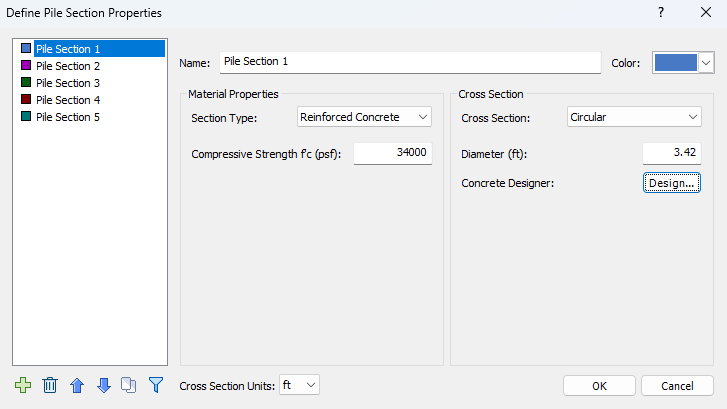
Pile Section Properties dialog - Reinforced Concrete Section - Click on the Design button to launch the Concrete Designer.
3.2 Concrete Designer
The Concrete Designer has 4 tabs, allowing users to fully define a reinforced concrete section. For more detailed information, we have the following help topics:
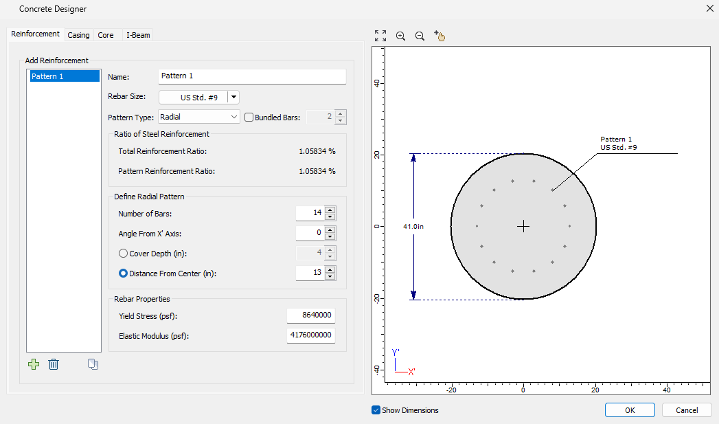
By default, the concrete section is not reinforced.
- In the Reinforcement tab, click on the Add
 icon to add and define a reinforcement pattern:
- Rebar Size = US Std. #9
- Pattern type = Radial
- Number of Bars = 14
- Angle from X Axis = 0
- Distance from Center (in) = 13
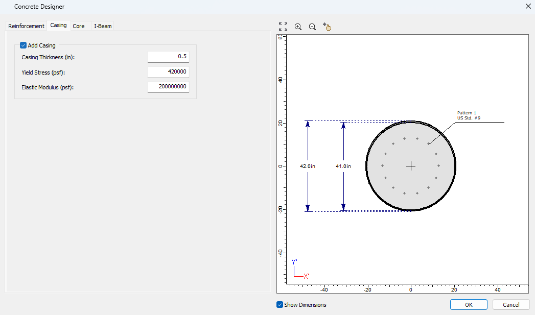
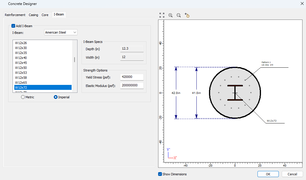
We will now add a casing in the Casing tab. This tab allows the user to add a casing and to specify the necessary parameters.
- Casing Thickness (in) = 0.5
- Yield Stress of Casing (psf) = 420,000
- Elastic Modulus of Casing (psf) = 200,000,000
- Type = American Steel
- W 12x72
- Yield Stress (psf) = 420,000
- Elastic Modulus (psf) = 200,000,000
4.0 Defining the Pile Type and Loading
We can now specify the pile loading.
- Select Piles > Single
 to open the Add Pile dialog.
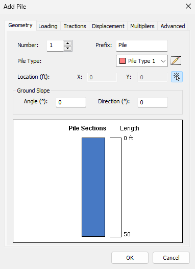
Add Pile - Geometry - In the Geometry tab, click on the Edit
 icon for Pile Type 1 and specify a Length of 50 ft.
 - Click OK to return to the Geometry tab. Leave everything else as the default values.
- In the Loading tab, add only a Moment Y of 50,000 lb-ft.
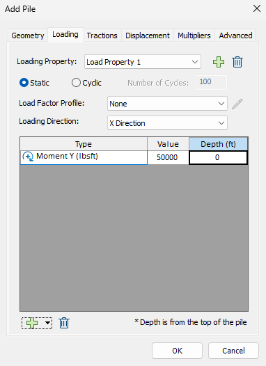
Add Pile - Loading - Click OK to exit the dialog and save your changes.
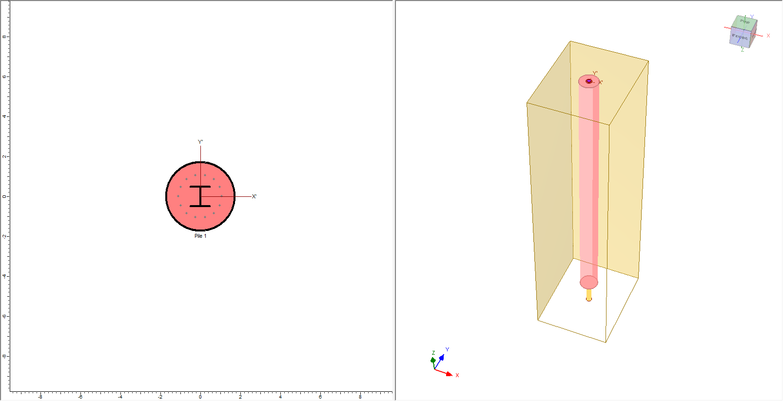
- You'll now be prompted to place the pile. Enter 0,0 in the command prompt in the bottom right of the screen and then press Enter.
You have now defined a reinforced concrete pile.
5.0 Results
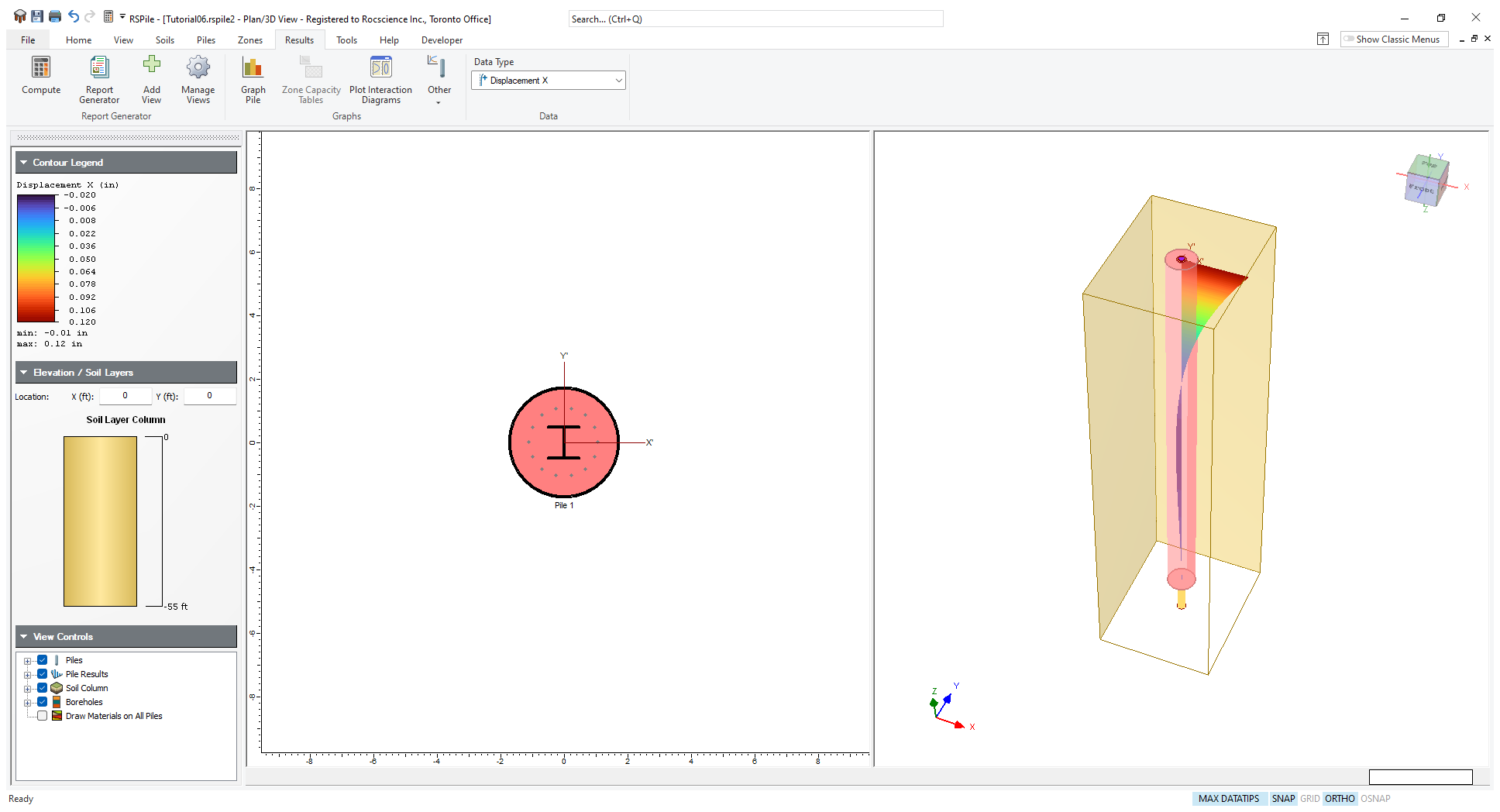
- Select Results > Compute
 to save and compute the model. You will then see the results as shown below.