12 - Capacity Table Generator
1.0 Introduction
This tutorial demonstrates how to analyze various bored pile types across different zones of the site and generate capacity tables and graphs in RSPile. The capacity tables and graphs contain comprehensive results for unfactored ultimate capacities and unit capacities, as well as factored allowable capacities which can be used to guide the allowable stress design of piles.
Topics Covered in this Tutorial:
- Multi-layer model
- Pile properties
- Pile types
- Zones
- Capacity tables
Finished Product:
The finished product of this tutorial can be found in the Tutorial 12 – Capacity Table Generator.rspile2 data file. All tutorial files installed with RSPile can be accessed by selecting File > Recent Folders > Tutorials Folder from the RSPile main menu.
2.0 Model
When the RSPile program is started, a new blank document is already opened, allowing you to begin creating a model immediately.
2.1 Project Settings
The Project Settings is where you can change the program mode selection, calculation or analysis type, and the number of pile segments to be used in the analysis.
To open the Project Settings:
- Select Home > Project Settings
 (CTRL + J).
 - In the General tab, set Units to USCS (Imperial)
and Program Mode Selection to Capacity Calculations.
- In the Capacity Calculations tab, set the Capacity Calculation Type to Capacity Table Generator.
Note that only Bored pile capacity calculations are available at the moment for Capacity Table Generator.
Due to uncertainties in the design and construction of piles, different partial safety factors can be applied to the calculated shaft friction and end bearing. - Under Calculate Allowable Capacities:
- Select the Total Capacity checkbox and set the associated factor FS1 to 2.5. This factor will be applied to the (combined) Ultimate Total Capacity to obtain the Allowable Total Capacity of the piles.
- Select the Skin Friction checkbox and set the associated factor FS2 to 2.0. This factor will be applied to the Ultimate Skin Friction Capacity to obtain the Allowable Skin Friction Capacity of the piles.
- Select the Skin Friction / End Bearing checkbox and set the associated factors FS3 to 1.5 and FS4 to 3.5. This factor will be applied to the Ultimate Skin Friction Capacity and Ultimate End Bearing Capacity (separately) to obtain the Allowable Skin Friction Capacity plus Allowable End Bearing Capacity of the piles.
- Select the Limit Average Stress checkbox. This will flag any allowable capacities in the Capacity Tables in RED if the value exceeds the calculated 25% allowable concrete cylinder strength of the pile.
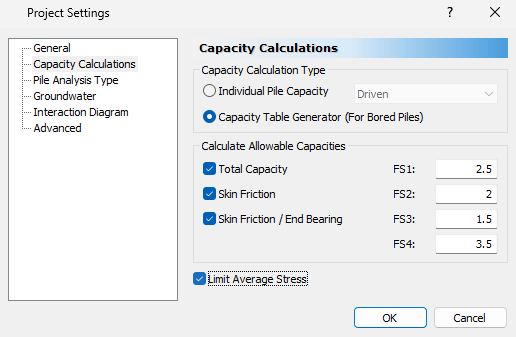
- Click OK to close the dialog.
3.0 Soils
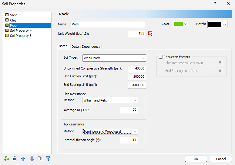
3.1 Soil Properties
- Select Soils > Define Soil Properties
 (CTRL + 8).
The Soil Properties dialog will appear allowing you to define different soil properties. - Define the material properties as shown below:
Soil Property 1:
- Name = Sand
- Unit Weight = 84.284 lbs/ft3
- Soil Type = Cohesionless
- Skin Friction Angle = 30 deg
- End Bearing Angle = 30 deg
- Method = Ks-Delta/NQ Method
- OCR = 1
- Ks/Ko = 0.7
- Delta/Phi = 1
- Bearing Capacity Factor Nq = 30
- Skin Friction Limit = 200000 psf
- End Bearing Limit = 2000000 psf
Soil Property 2:
- Name = Clay
- Unit Weight = 62 lbs/ft3
- Soil Type = Cohesive
- Method = Total Stress Calculations - Alpha Method
- Alpha = 0.4
- Undrained Shear Strength Su = 1000 psf
- Bearing Capacity Factor Nc = 9
- Skin Friction Limit = 200000 psf
- End Bearing Limit = 2000000 psf
Soil Property 3:
- Name = Rock
- Unit Weight = 131 lbs/ft3
- Soil Type = Weak Rock
- Unconfined Compressive Strength = 40000 psf
- Skin Friction Limit = 200000 psf
- End Bearing Limit = 2000000 psf
- Skin Resistance Method = William and Pells
- Average RDQ % = 35%
- Tip Resistance Method = Tomlinson and Woodward
- Internal Friction Angle = 25 deg
3.2 Edit Boreholes
RSPile supports multiple boreholes and non-horizontal soil strata. When multiple boreholes are defined, the program will automatically interpolate between the boreholes. In this tutorial, we will model non-horizontal soil strata with multiple boreholes. To begin:
- Select Soils > Edit All
 to open the Edit Borehole icon.
 - Click on Add borehole
 twice to add 2 more boreholes (Borehole 2 and Borehole 3)
 - Select Borehole 1 and then click on Insert Layer Below
 twice to add two layers below the first.
 - Change the order of the Soil Layers such that it is ordered as Sand, Clay, then Rock.
Define the boreholes as shown below:
Borehole 1
Borehole 2
Borehole 3
Location
X = 0 ft, Y = 0 ft
X = 100 ft, Y = 0 ft
X = 0 ft, Y = 100 ft
Borehole Top Elevation
0 ft
5 ft
20 ft
Sand Thickness
20 ft
60 ft
80 ft
Clay Thickness
30 ft
0 ft
15ft
Rock Thickness
50 ft
45 ft
15ft
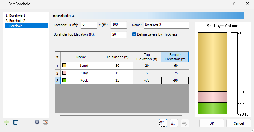
- Click OK to close the dialog.
The soil column is created by interpolating the soil layer information between the three boreholes:
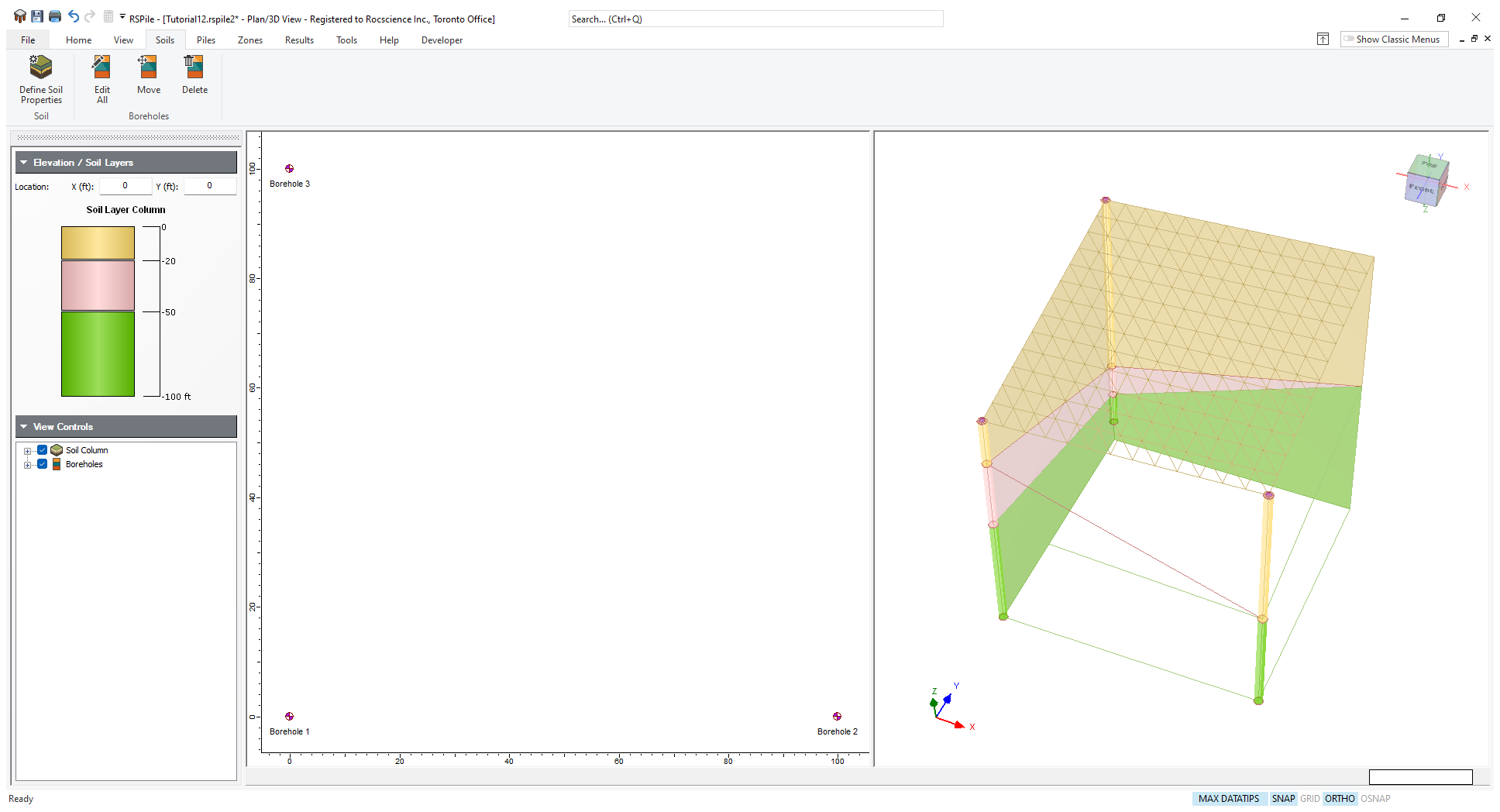
The soil surface elevation and soil layer profile vary depending on location. In order to investigate numerous pile types over different locations, we can use zones to delineate the site extents and calculate pile capacities for various pile types.
First, let’s define the pile section properties and pile types.
4.0 Piles
4.1 Pile Section Properties
Let’s create 3 different pile section designs, all with a circular cross section, but different diameters.
- Select Piles > Pile Sections
 to open the Define Pile Section Properties dialog.
 - Define the pile section properties as shown below:
Pile Section 1:
- Cross Section = Circular
- Diameter = 2 ft
- Concrete Cylinder Strength = 850000 psf
Pile Section 2:
- Cross Section = Circular
- Diameter = 2.5 ft
- Concrete Cylinder Strength = 850000 psf
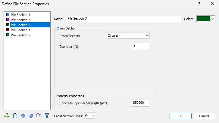
Pile Section 3:
- Cross Section = Circular
- Diameter = 3 ft
- Concrete Cylinder Strength = 850000 psf
4.2 Pile Types
Now let’s create six different pile types using the three section properties from earlier. The first three pile types will be a single uniform section, and the last three pile types will be a single uniform section with bell (Note for the design of the bell, we will be using the default dimensions in Edit Bell dialog).
- Select Piles > Pile Types
 to open the Edit Pile Types dialog.
 Define the pile section properties as shown below:
Cross Section Type Section Property 1 Section Property 2 Pile Type 1 Uniform Pile Section 1, Length = 15 ft - Pile Type 2 Uniform Pile Section 2, Length = 15 ft - Pile Type 3 Uniform Pile Section 3, Length = 15 ft - Pile Type 4 Uniform with Bell Pile Section 1, Length = 15 ft Bell Pile Type 5
Uniform with Bell Pile Section 2, Length = 15 ft Bell Pile Type 6 Uniform with Bell Pile Section 3, Length = 15 ft Bell 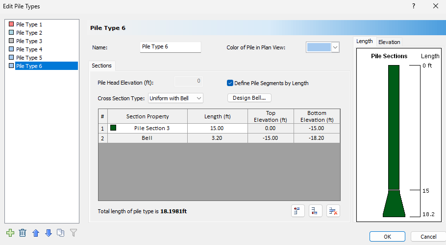
- Click OK to close the dialog.
Now we are ready to delineate the area into different zones and perform capacity analysis on all the pile types.
5.0 Zones
5.1 Adding Zones
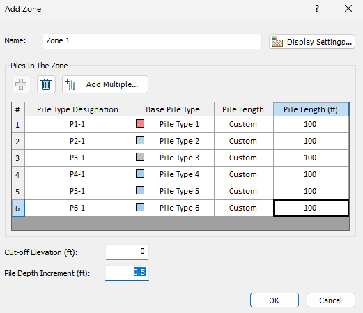
Since different locations have different soil properties, we can simplify the analysis by assuming an average soil column over the area of a convex polygon and perform our pile capacity on the six different pile types inside that soil column; this hypothetical soil column is referred to as a “Zone”. Within a Zone, the soil surface elevation and soil layers are interpolated from the geometric centroid of the Zone polygon. You can add any or all pile types defined in the Edit Pile Types dialog (given that they are single section, or single section with bell).
We will define three Rectangular Zones to characterize the ‘averaged’ soil properties over various areas.
To add a Rectangular Zone:
- Select Zones > Rectangle

- Set the Name = Zone 1.
- Click the Add button 5 times to add all 6 Base Pile Types. Alternatively, click the Add Multiple
 button, select Select All and click OK.
 - The Pile Length is set to Default. Override this value by changing the Pile Length to Custom for all piles.
- Change the Pile Length to 100 ft for all piles.
- Set the Cut-off Elevation to 0 ft. This applies to all piles in the Zone and overrides the Pile Head Elevation in the Edit Pile Types dialog.
- Set the Pile Depth Increment to 0.5 ft. This applies to all piles in the Zone and overrides Depth Increment in Advanced Project Settings.
- Define the first corner of the Zone rectangle. Enter (-50, 50).
- Define the second corner of the Zone rectangle. Enter (50, 150).
- Click OK to close the dialog.
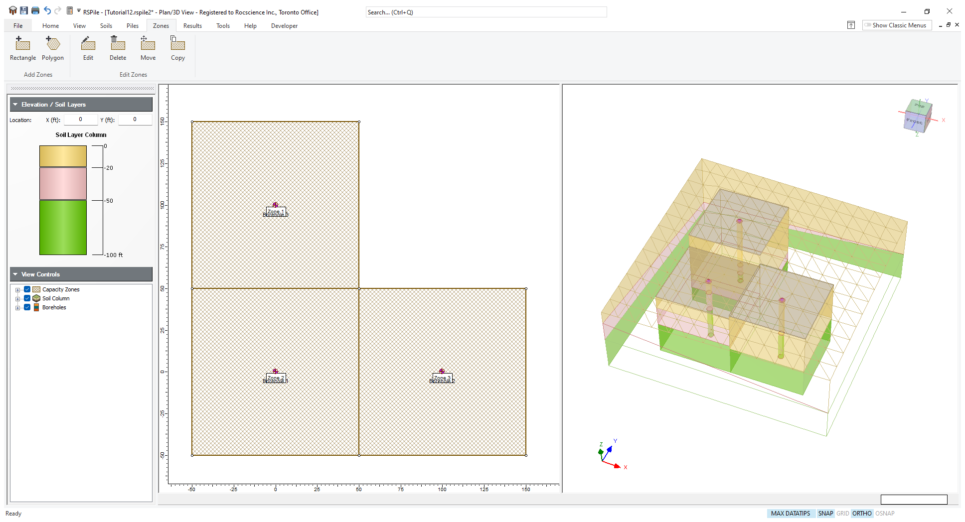
Zone 1 appears in the north-west quadrant of the site, and the pile locations are sampling at the center of the zone (which so happens to coincide with Borehole 3.
To create two more Zones with the same pile types, we can use the Add Zone option again. To save time, we can use Copy Zone instead to duplicate Zone 1 and place the new Zones at the south-west and south-east quadrants.
To copy a Zone:
- Select Zone > Copy Zone and left-click on Zone 1 or right-click on Zone 1 and select Copy Zone
 .
. - Type @0,-100 in the command prompt and hit ENTER to copy and move relative 100 ft to the south.
- Right-click on Zone 2 and select Copy Zone .
- Type @100,0 in the command prompt and hit ENTER to copy and move relative 100 ft to the east.
Now you should have three Zones: Zone 1 in the north-west quadrant, Zone 2 in the south-west quadrant, and Zone 3 in the south-east quadrant:
Let’s take a look at Zone 2. You can edit the Name, Zone Coordinates, Piles in the Zone, Cut-off Elevation, or Pile Depth Increment at any time using the Edit Zone option.
To edit Zone 2:
- Right-click on Zone 2.
- Select Edit Zone
 from the right-click menu.
 - Note that the Name and Pile Type Designations are automatically reassigned. Leave the settings unchanged.
- Select OK to close the dialog.
6.0 Results
- Save and compute the file by selecting Results > Compute

6.1 Capacity Tables and Charts
From the computed capacity data, RSPile can generate a set of capacity tables and charts for all piles within the Zone.
- Select Results > Zone Capacity Tables

- Click on Zone 1 in the Plan View.
The RSPile Pile Capacity Table section presents several default graphs and a table of pile capacity results for the selected Zone. You should see the following:
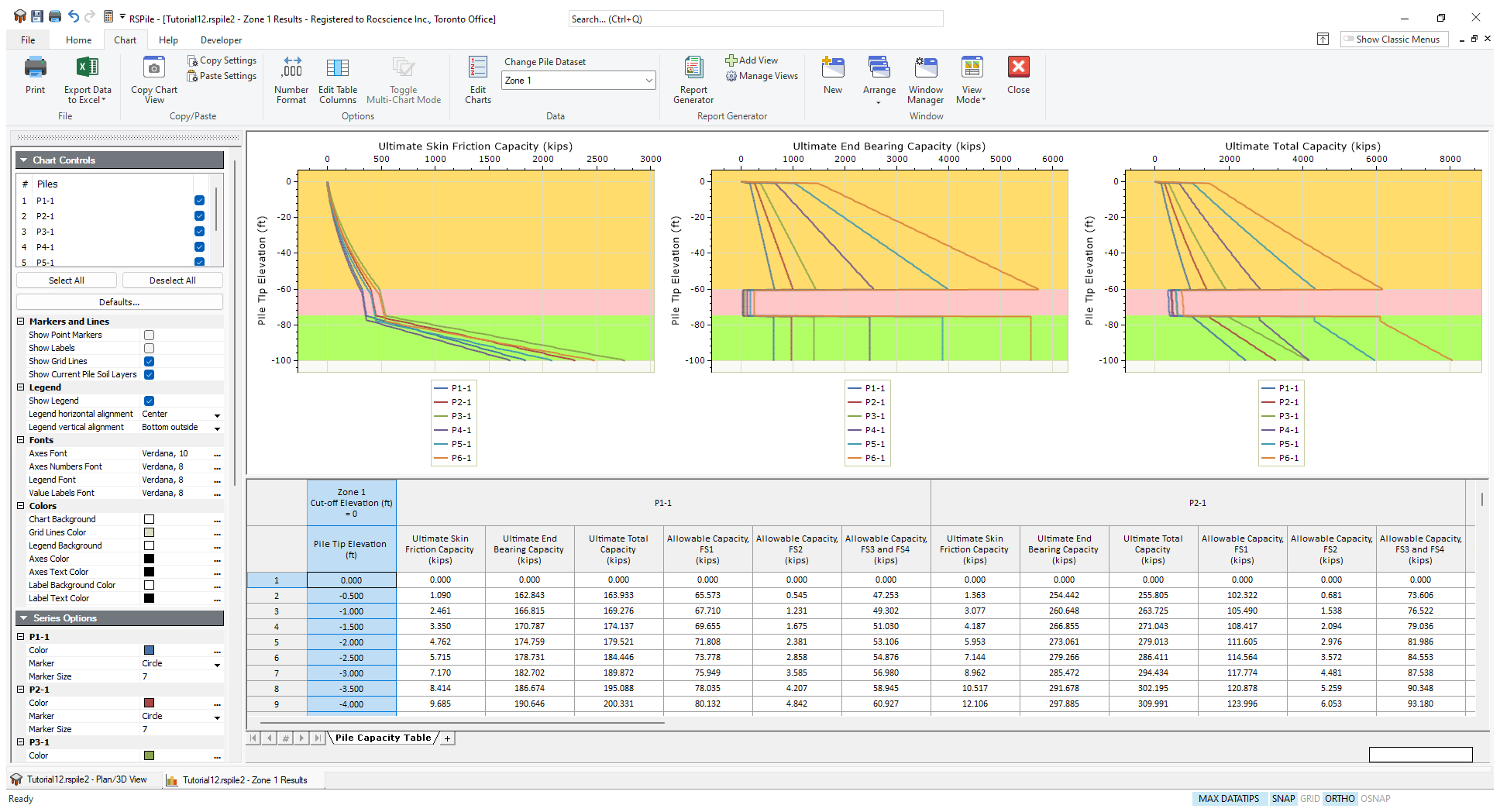
By default, the following three graphs are shown:
- Ultimate Skin Friction Capacity vs. Pile Tip Elevation
- Ultimate End Bearing Capacity vs. Pile Tip Elevation
- Ultimate Total Capacity vs. Pile Tip Elevation
In the table, the following columns are shown:
- Pile Tip Elevation
- Ultimate Skin Friction Capacity (for each pile)
- Ultimate End Bearing Capacity (for each pile)
- Ultimate Total Capacity (for each pile)
Since we have factors under Calculate Allowable Capacities selected in Project Settings, the table also contains factored allowable capacities:
- Allowable Capacity, FS1 (for each pile)
- Allowable Capacity, FS2 (for each pile)
- Allowable Capacity, FS3 and FS4 (for each pile)
Maximize the Table by clicking Chart > View Mode > Maximize Grid.
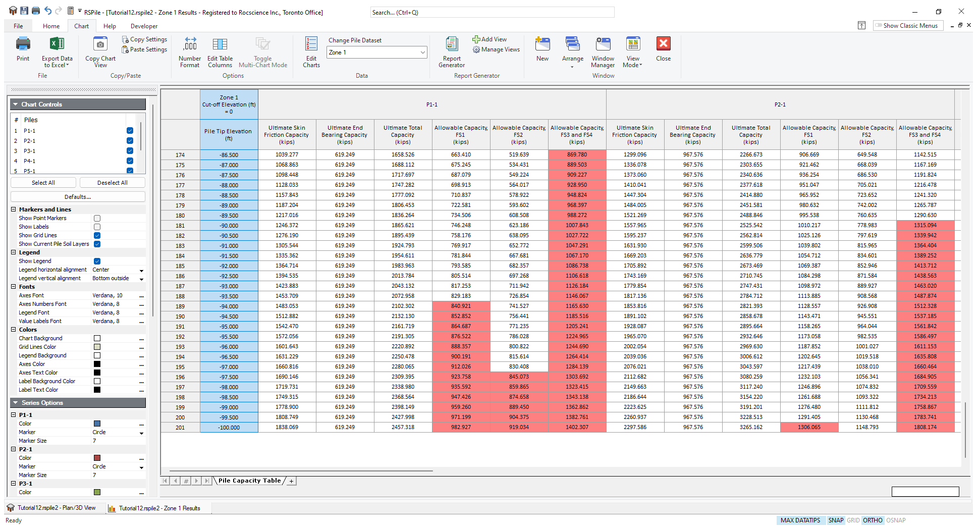
Note the allowable capacities highlighted in red. These values represent allowable capacities which exceed the allowable concrete cylinder strength (Project Settings > Limit Average Stress) of the pile. In the design of piles, both the soil capacity and material strength capacity must be checked.
Additional data types can be graphed or added as columns in the table using the Edit Charts and Edit Table Columns options respectively. In addition to the default data types shown, the following data can also be graphed or included in the table:
- Unit Skin Friction (for all piles)
- Unit End Bearing (for all piles)
You can easily toggle the display of piles displayed using the Chart Controls pane in the Sidebar.
To view Pile Capacity Tables for other Zones, select the Zone from the dropdown in the toolbar.
6.2 Export To Excel
From the Pile Capacity Table tab, you can export your data to Excel.
To export data to Excel:
- Select on Chart > Export Data to Excel

Data for each Zone is exported to its own sheet in the Excel file.
This concludes the Capacity Table Generator Tutorial. You may now exit the RSPile program.