9 - Telescopic Drilled Pier with Bell
1.0 Introduction
In this tutorial a telescopic bored pile with enlarged base is solved for carrying capacity using the program RSPile. Before proceeding with the tutorial, make sure you’ve gone through Tutorial 01 - RSPile Quick Start so you’re familiar with the product’s basic functions and features.
Topics Covered in this Tutorial:
- Defining Pile Sections
- Pile Types
- Designing Bells
Finished Product:
The finished product of this tutorial can be found in the Tutorial 9 - Telescopic Drilled Pier with Bell.rspile2 data file. All tutorial files installed with RSPile can be accessed by selecting File > Recent Folders > Tutorials Folder from the RSPile main menu.
2.0 Model
When the RSPile program is started, a new blank document is already opened, allowing you to begin creating a model immediately.
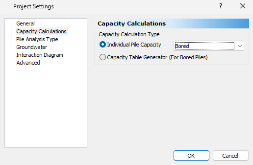
2.1 PROJECT SETTINGS
- Select Home > Project Settings
 (CTRL + J).
 - In General tab, set the Units to SI (Metric) and Program Mode Selection to Capacity Calculations.
- Select the Capacity Calculations tab and set the Capacity Calculation Type to Bored.
- Select the Groundwater tab. Tick the checkbox for Groundwater Analysis. Set the Water Table Elevation (m) to -2.
- Select the Advanced tab to see the Advanced Settings and set the step length for showing capacity results.
- Set the Pile Discretization to Custom.
- In this example the results are presented every 1 m as indicated in the Pile Depth Increment (m) field.
- Set the number of Pile Segments to 50.
- Click OK to close the dialog.
3.0 Soils
From the ground surface we will be defining a 12m layer of cohesive stiff clay overlaying another 12m layer of cohesionless soil, as well as a water table.
3.1 SOIL PROPERTIES
- Select Soils > Define Soil Properties
 (CTRL + 8).
 - Select each soil property in the left side bar and enter the following soil profile data:
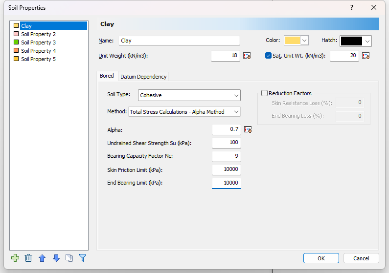
Soil Property 1 (Cohesive Clay):
- Name = Clay
- Unit weight = 18
- Saturated unit weight = 20
- Soil Type = Cohesive
- Method = Total Stress Calculations - Alpha method
- Alpha = 0.4
- Undrained shear strength Su = 100 kPa
- Bearing Capacity Factor Nc = 9
- Since no cap is applied for capacity the Skin Friction and End Bearing limits are set to 10000 kPa.
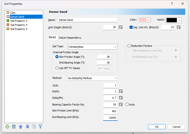
Soil Property 2 (Cohesionless Sand):
- Name = Dense Sand
- Unit weight = 20 kN/m3
- Unit Saturated unit weight = 22 kN/m3
- Soil Type = Cohensionless
- Internal friction Angle
- Skin Friction Angle = 38
- End Bearing Angle = 38
- Method = Ks-Delta/NQ Method
- OCR = 1
- Ks/Ko = 1
- Delta/phi =0.7
- Bearing Capacity Factory Nq = 50
- The skin friction is capped with 400kPa.
- The end bearing is left uncapped and uses value of 10000 kPa.
3.2 EDIT BOREHOLE
Next we will use the Borehole Editor to define our borehole and layer thicknesses.
- Select Soils > Edit All
 to open the Edit Borehole dialog.
As mentioned in the previous section, each layer will have a thickness of 12 m.
- Click on the Insert Layer Below button to insert the second layer. The Clay and Dense Sand properties should be applied automatically.
- Change the thickness for Layer 1 and 2 to 12 m.
- Set the x,y location to (2,2)
- The Borehole Top Elevation will remain as 0.
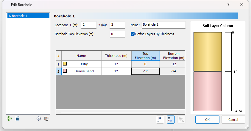
- Click OK to close the dialog.
4.0 Piles
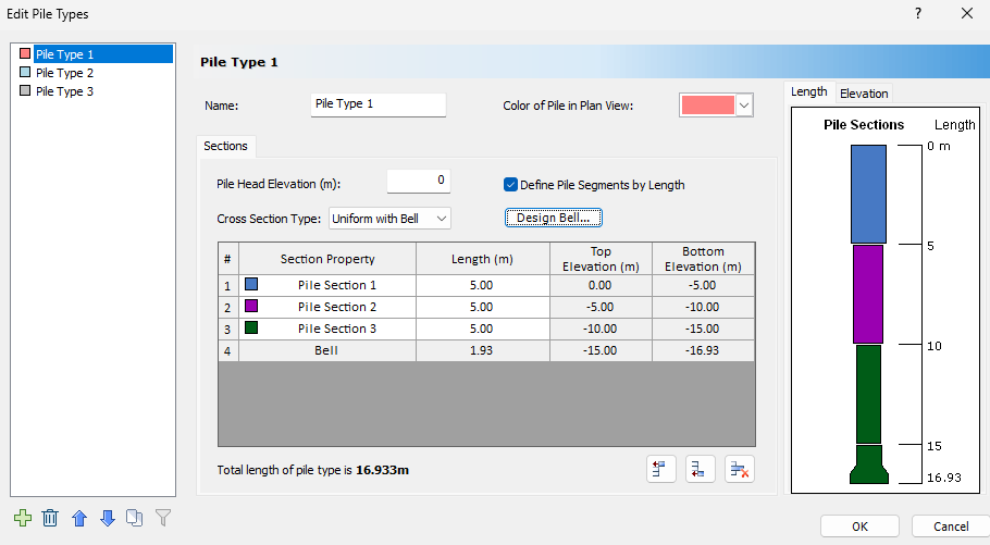
The pile for this example is a telescopic pile with three segments that are 5 m in length each and a bottom piece that is extended with a bell of 1.93 m.
4.1 DEFINE PILE SECTIONS PROPERTIES
The three sections we are creating have diameters of 1.4 m, 1.2 m, and 1.0 m respectively with the same concrete strength of 40MPa.
To define the properties of each section:
- Select Piles > Pile Sections
 to open the Pile Section Properties dialog.
 - Select Pile Section 1.
- The Pile Cross section shoud be set to Circular.
- Enter a diameter (m) of 1.4 m.
- Concrete Cylinder Strength (kPa) = 40000.
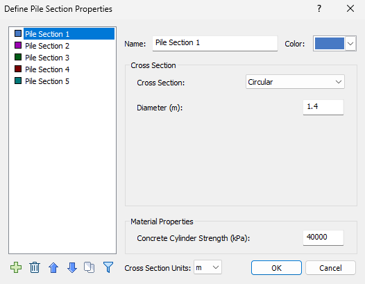
- Select Pile Section 2. The properties should be the same as Pile Section 1 but with a diameter of 1.2 m.
- Select Pile Section 3. The properties should be the same as Pile Section 1 but with a diameter 1 m.
- Click OK to close the dialog.
4.2 EDIT PILE TYPE
The defined pile sections can now be used in our Pile Type.
To define the Pile Type:
- Select Piles > Pile Types
 to open the Edit Pile Types dialog.
 - Set the Cross Section Type to Uniform with Bell.
- Click on the Insert Below icon twice to insert Pile Section 2 and 3.
- Set the Length for each pile section to 5 m.
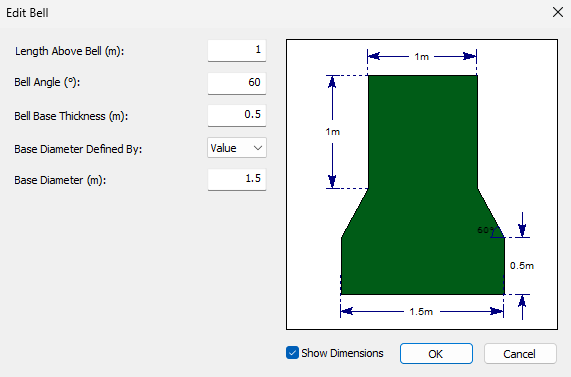
- Click on Design Bell.
- Enter the following Bell Properties:
- Length Above Bell (m) = 1
- Bell Angle = 60
- Bell Base Thickness (m) = 0.5
- Base Diameter (m) = 1.5
4.3 ADD PILE
- Select Piles > Single

- Pile Type 1 should be selected by default.
- Click OK.
- Enter the Pile Location in the Prompt line at the bottom right of the screen as (0,0) or use your mouse to place the pile in the plan view.
5.0 Results
5.1 COMPUTE
- Save and compute the file by selecting Results > Compute

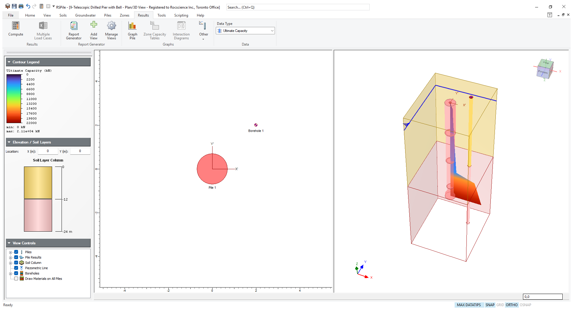
5.2 GRAPH PILE
Detailed tables and charts of your results can be obtained by right clicking on the pile and selecting Graph Pile or by clicking on the Graph Pile  icon in the toolbar and selecting the pile in the plan view.
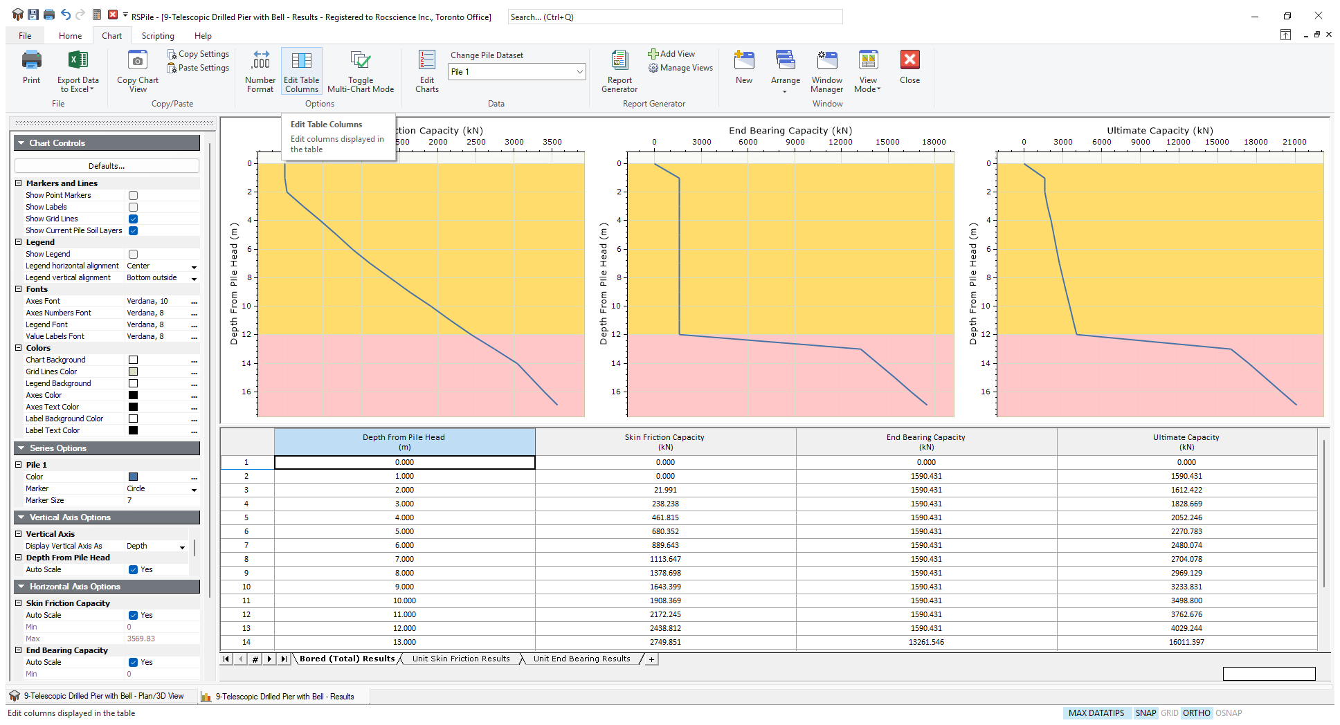
In the graph view you can see graphs for Skin Friction, End Bearing and Ultimate Capacity as well as a table of values below.
From the analysis for this example we have learned:
Ultimate skin resistance of the pile:
- In the clay layer is 70 kPa.
- In the sand layer is varied from 26.95 to 32.56 kPa.
- The skin resistance is decreased to zero at the bell part.
Ultimate end bearing of the pile:
As laid at 16.93m below ground surface the enlarged base gave an ultimate unit end bearing resistance of 9899.85 kPa (note that it is still below the default cap of 10000). While the ultimate unit end bearing resistance in the clay layer was 900kPa.
Total ultimate capacity:
The total ultimate capacity of the pile is 21092.36 kPa as may be found at the bottom row of the capacity table.