13 - Off-Shore Pile
1.0 Introduction
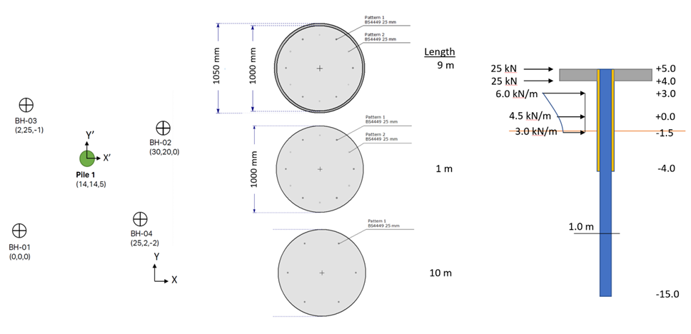
In the following tutorial, we will analyze an offshore pile installed in shallow sea water near the shore with uneven seabed and ground layers defined with 4 boreholes. (See the figure below.)
Want to watch the video version of the tutorial? Check it out here:
Problem description
The pile is a 20m long reinforced concrete bored pile with permanent casing for the first 9m. The pile diameter is 1m and the casing thickness is 25mm. The pile is reinforced with 12-25mm bars for the first 10m decreased to half for the rest of the pile.
The pile head is restrained from rotation for 1m because of the platform jacket. The loading case analyzed in this example is in one horizontal direction. The loads comprise of 50 kN from the jacket (divided for the purpose of analysis into two 25kN concentrated horizontal loads at pile head and 1m depth). In addition, the distributed wave load given as a traction +3.0 to -1.5 is approximated as linear loads.
The rotational restrains are modelled as very large stiffness values at +5 and +4.0 elevations. The concrete cylinder strength is taken as 40MPa, and the reinforcement bars have a yield strength of 420MPa and a modulus of elasticity of 200GPa while the casing has a yield strength of 350MPa.
Topic Covered in this Tutorial:
- Off-shore pile analysis
- Lateral loads and tractions
- Uneven Soil layers
- Multiple boreholes
- Surface water
Finished Product:
The finished product of this tutorial can be found in the Tutorial 13 - Off-Shore Pile data file. All tutorial files installed with RSPile can be accessed by selecting File > Recent Folders > Tutorials Folder from the RSPile main menu.
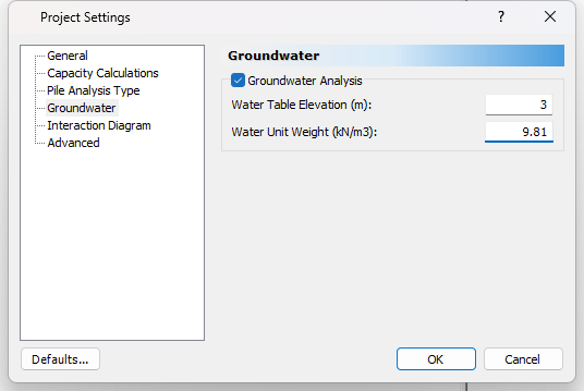
2.0 Project Settings
- Select Home > Project Settings
 (CTRL + J).
 - Select the General tab and enter the following:
- Units = SI (Metric)
- Program Mode Selection = Pile Analysis
3.0 Soils
3.1 Soil Properties
- Select Soils > Define Soil Properties
 icon in the toolbar.
 - Enter the following soil properties:
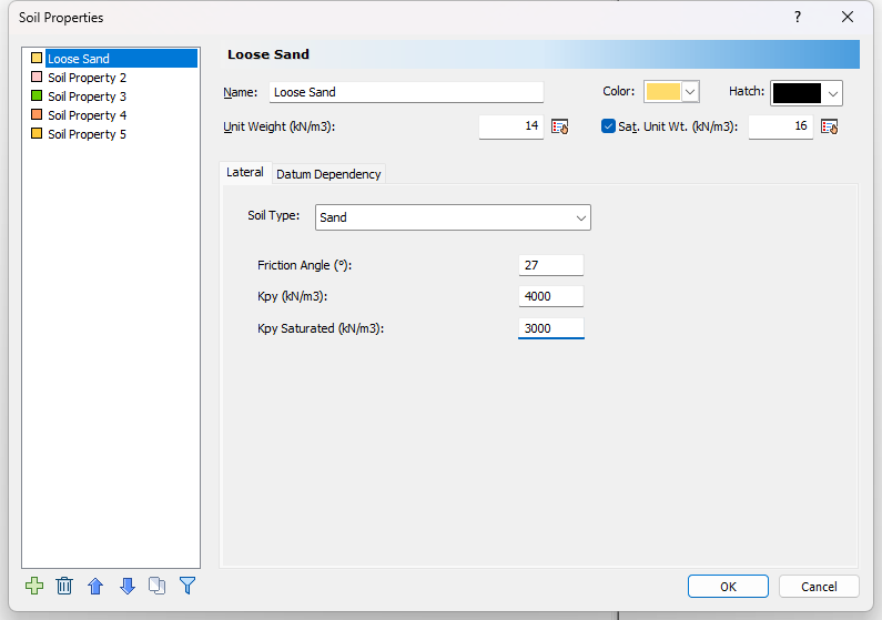
Soil Property 1:
- Name = Loose Sand
- Unit Weight = 14 kN/m3
- Check box for Saturated Unit Weight = 16 kN/m3
- Soil Type = Sand
- Friction Angle = 27 degrees
- Kpy = 4000 kN/m3
- Kpy Saturated = 3000 kN/m
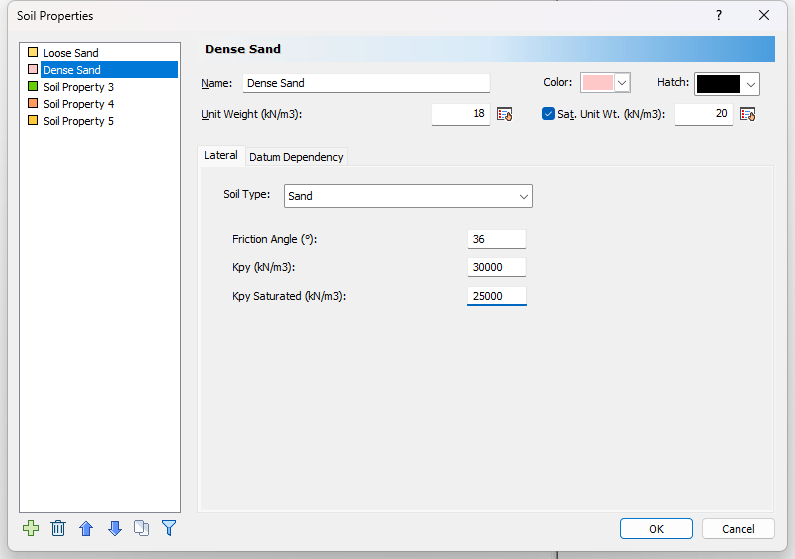
Soil Property 2:
- Name = Dense Sand
- Unit Weight = 18 kN/m3
- Check box for Saturated Unit Weight = 20 kN/m3
- Soil Type = Sand
- Friction Angle = 36 degrees
- Kpy= 30000 kN/m3
- Kpy Saturated = 25000 kN/m3
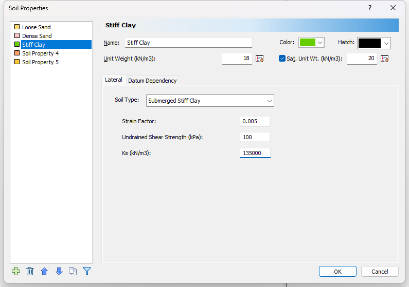
Soil Property 3:
- Name = Stiff Clay
- Unit Weight = 18 kN/m3
- Check box for Saturated Unit Weight = 20 kN/m3
- Soil Type = Submerged Stiff Clay
- Strain Factor = 0.005
- Undrained Shear Strength (kPa) = 100 kPa
- Ks = 135000 kN/m3
3.2 Edit Boreholes
- Select Soils > Edit All
 to open the Edit Borehole dialog.
 - Add 3 boreholes by clicking the Add
 button. There should be 4 boreholes total.
 - Select Borehole 1. Click Insert Layer Below
 twice to add the Dense Sand and Stiff Clay layers. Then enter the borehole information as per the table below:
Borehole |
X, Y, Elevation |
# Layer |
Name |
Thickness |
Top Elevation |
Bottom Elevation |
Borehole 1 |
0,0,0 |
1 |
Loose Sand |
3 |
0 |
-3 |
2 |
Dense Sand |
6 |
-3 |
-9 |
||
3 |
Stiff Clay |
20 |
-9 |
-29 |
||
Borehole 2 |
30,20,0 |
1 |
Loose Sand |
5 |
0 |
-5 |
2 |
Dense Sand |
5 |
-5 |
-10 |
||
3 |
Stiff Clay |
20 |
-10 |
-30 |
||
Borehole 3 |
2,25,-1 |
1 |
Loose Sand |
6 |
-1 |
-7 |
2 |
Dense Sand |
6 |
-7 |
-13 |
||
3 |
Stiff Clay |
20 |
-13 |
-33 |
||
Borehole 4 |
25,2,-2 |
1 |
Loose Sand |
3 |
-2 |
-5 |
2 |
Dense Sand |
4 |
-5 |
-9 |
||
3 |
Stiff Clay |
20 |
-9 |
-29 |
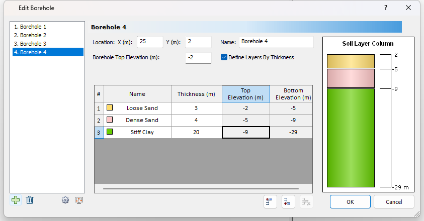
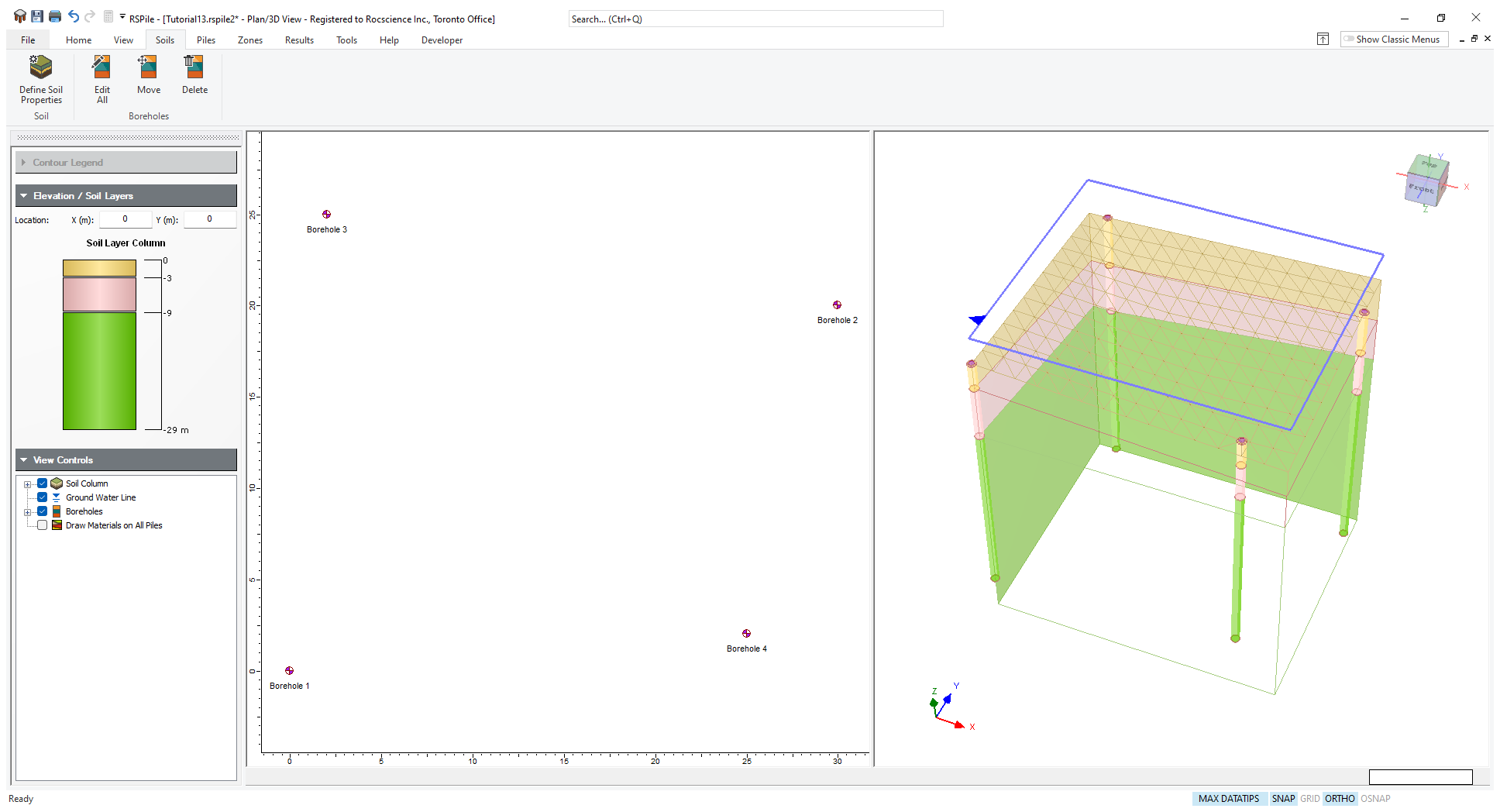
Your model should look as follows:
4.0 Piles
4.1 Define Pile Section Properties
- Select Piles > Pile Sections
 to open the Define Pile Section Properties dialog.
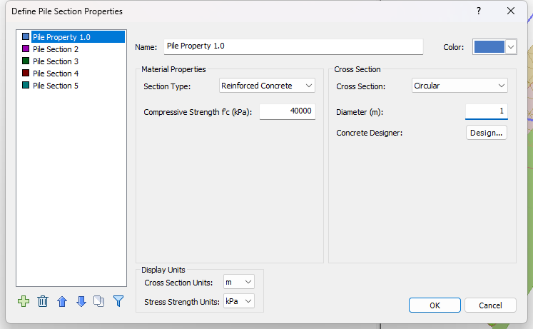
 - Create 3 Pile Sections Properties and name them as:
- Pile Property 1.0
- Pile Property 1.1
- Pile Property 1.2
Name |
Section Type |
Compressive Strength f’c (kPa) |
Cross Section |
Diameter (m) |
Pile Property 1.0 |
Reinforced Concrete |
40000 |
Circular |
1.0 |
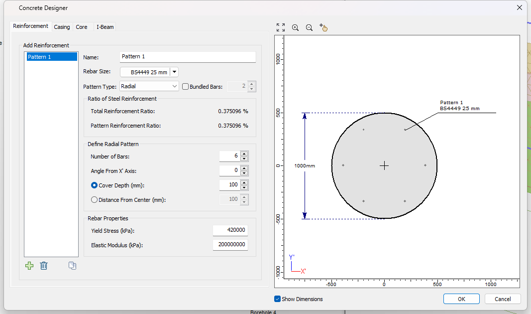
Reinforcement Tab
Pattern 1
- Rebar Size = Europe > BS4449 25mm
- Pattern type = Radial
- Number of Bars = 6
- Angle from X Axis = 0
- Cover Depth (mm) = 100
- Yield Stress (kPa) = 420 000
- Elastic Modulus (kPa) = 200 000 000
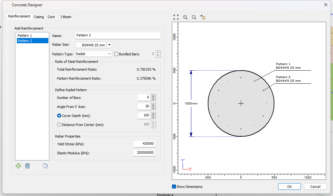
Pattern 2
- Rebar Size = Europe > BS4449 25mm
- Pattern type = Radial
- Number of Bars = 6
- Angle from X Axis = 30
- Cover Depth = 100 mm
- Yield Stress = 420 000 kPa
- Elastic Modulus = 200 000 000 kPa
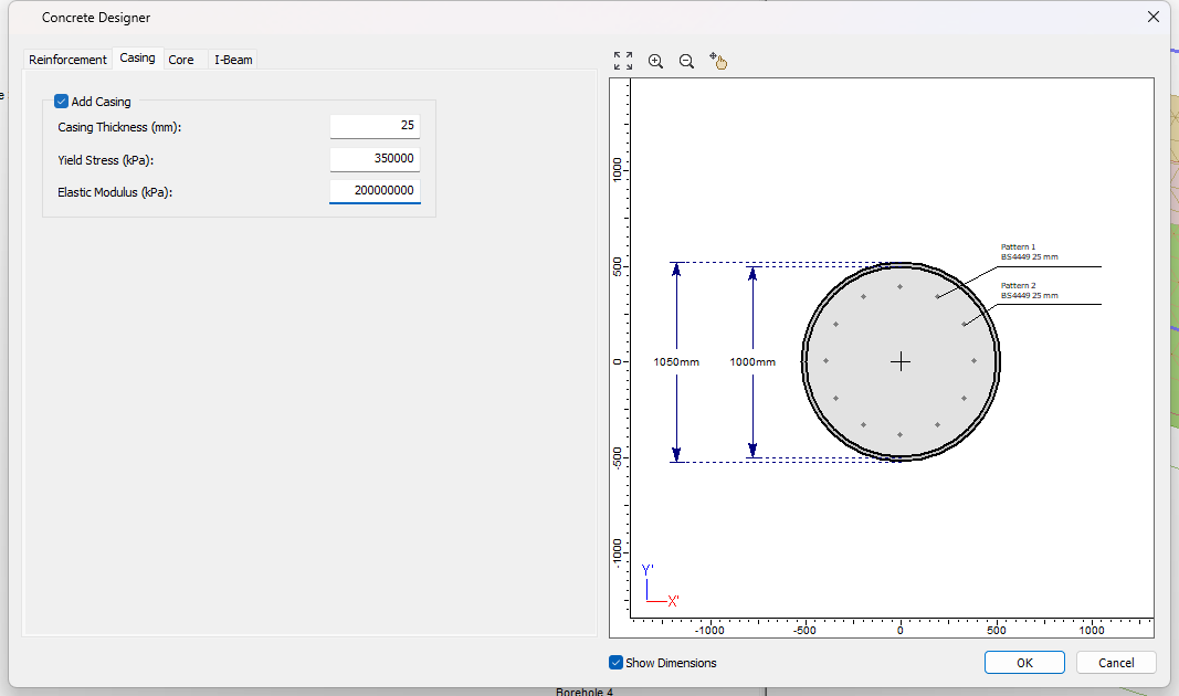
Casing Tab
- Casing Thickness = 25 mm
- Yield Stress = 350 000 kPa
- Elastic Modulus = 200 000 000 kPa
- In the Define Pile Section Properties dialog, select the Copy icon
to copy the Pile Property 1.0 to Pile Property 1.1 and Pile Property 1.2. Select both pile properties and click OK.
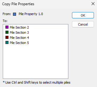
Copy Pile Properties - In the Pile Section Properties dialog select Pile Property 1.1:
- Click on the Concrete Designer Design.. button.
- Go to the Casing tab.
- Uncheck Add Casing.
- Click OK to close the Concrete Designer dialog.
- Click on the Concrete Designer Design.. button.
- Delete Pattern 2.
- Go to the Casing tab.
- Uncheck Add Casing.
- Click OK to close the Concrete Designer dialog.
4.2 Edit Pile Types
- Select Piles > Pile Types
 to open the Edit Pile Types dialog.
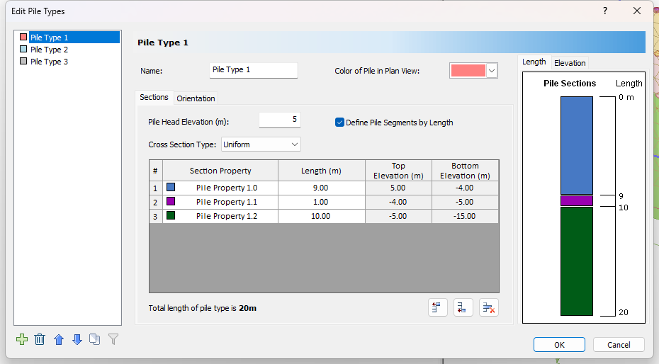
 - In the Sections tab, set Pile Head Elevation = 5m and Cross Section Type as Uniform.
- Click the Insert Layer Below button twice to add sections 1.1 and 1.2.
- Edit the Length (m) of the Pile Section Properties as per the table below.
Section Property |
Length (m) |
Top Elevation (m) |
Bottom Elevation (m) |
Pile Property 1.0 |
9.00 |
5.00 |
-4.00 |
Pile Property 1.1 |
1.00 |
-4.00 |
-5.00 |
Pile Property 1.2 |
10.00 |
-5.00 |
-15.00 |
4.3 Add Pile
- Select Piles > Single
 icon to open the Add Pile dialog.
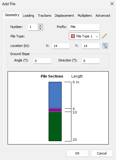
 - In the Geometry tab, toggle off the Mouse icon to specify the Pile 1 Location as X = 14 and Y = 14.
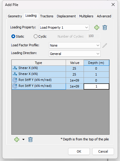
Add Pile - Geometry - In the Loading tab, click the Add icon to add a Load Property.
- For the Loading Direction select General.
- Click on the Add icon in the bottom left and add the loads as per the table below:
Type |
Value |
Depth |
Force X (kN) |
25 |
0 |
Force X (kN) |
25 |
1 |
Rotational Stiffness Y (kNm/rad) |
1e+09 |
0 |
Rotational Stiffness Y (kNm/rad) |
1e+09 |
1 |
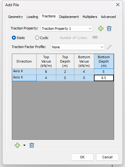
- In the Tractions tab click the Add icon to add a Traction Property.
- Click on the Add icon in the bottom left to add the traction loads as per the table below:
Direction |
Top Value (kN/m) |
Top Depth (m) |
Bottom Value (kN/m) |
Bottom Depth (m) |
Axis X |
6 |
2 |
4 |
5 |
Axis X |
4 |
5 |
3 |
6.5 |
- Click OK to close the dialog and place the pile.
5.0 Compute
- Select Results > Compute
 to save and compute the model.
6.0 Results
