10 - Telescopic Pile Analysis
1.0 Introduction
In this tutorial the same pile of Tutorial 9: Telescopic Drilled Pier with Bell is analyzed for a lateral load of 1000 kN and a vertical load of 4000 kN using the program RSPile.
Topics covered:
- Axially/Laterally Loaded
- Defining Pile Sections
- Pile Types
Finished Product:
The finished product of this tutorial can be found in the Tutorial 10 - Telescopic pile analysis under lateral and axial load.rspile2 data file. All tutorial files installed with RSPile can be accessed by selecting File > Recent Folders > Tutorials Folder from the RSPile main menu.
2.0 Model
Open the Tutorial 9 - Telescopic Drilled Pier with Bell.rspile2 data file by selecting File > Recent Folders > Tutorials Folder from the RSPile main menu.
2.1 PROJECT SETTINGS
- Select Home > Project Settings
 (CTRL + J).
 - In the General tab, change the Program Mode Selection to Pile Analysis.
- Go to the Pile Analysis Type tab and select Individual Pile Analysis = Axially / Laterally Loaded.
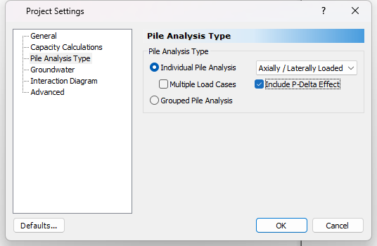
- Go to the the Advanced tab to choose your accuracy tolerance and other solution controls:
- Pile Discretization = Custom
- Pile Segments = 50
- Convergence Tolerance = 0.0001
- Number of Iterations = 100
- Reinforced Concrete Slices = 100
- Use Method of Georgiadis Layering Effect = Yes
3.0 Soil
3.1 DEFINE SOIL PROPERTIES
The soil layers are the same as Tutorial 9 but the soil models required for Lateral Analysis and Axial Analysis are chosen with the suitable parameters as follows:
- Select Soils > Define Soil Properties
 to open the Soil Properties dialog.
 - Edit the soil properties as follows:
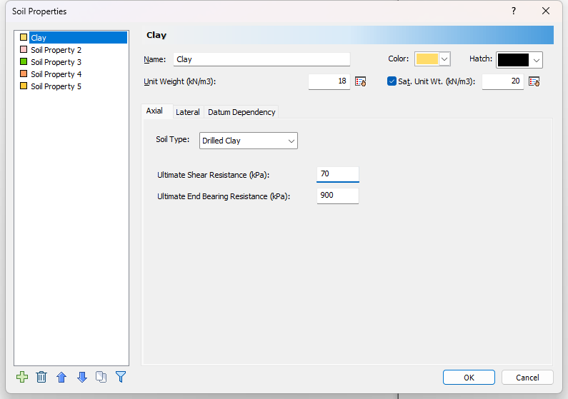
For Clay:
- In the Lateral tab set the Soil Type as the Submerged stiff clay model and keep the same undrained shear strength. Change Ks (kN/m3) to 200000.
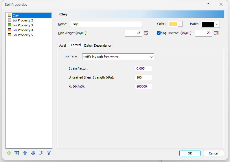
- In the Axial tab set the Soil Type as the Drilled Clay model, while copying the calculated unit skin resistance and end bearing resistance from the previous tutorial results: 70 and 900 kPa respectively.
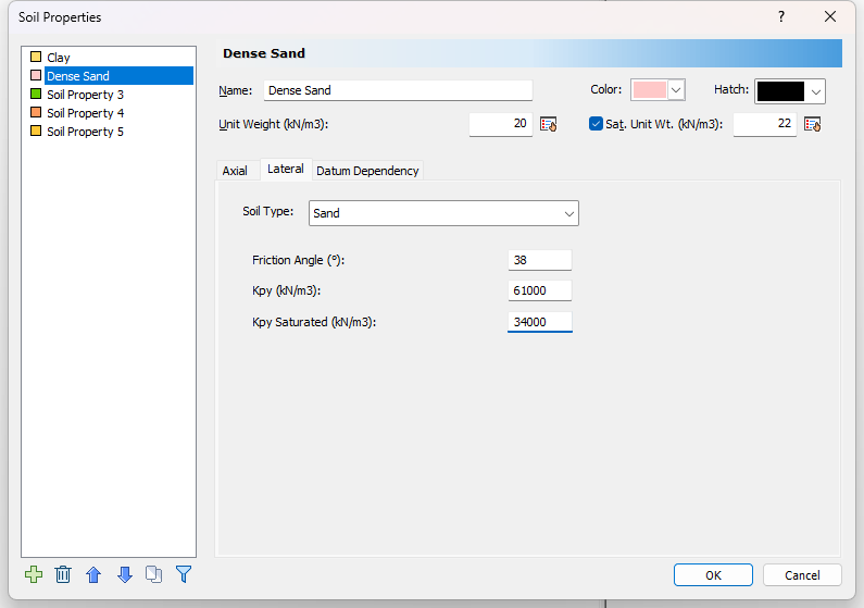
For Dense Sand:
- In the Lateral tab set the soil type as the Sand model. Enter the Friction angle as 38, Kpy (kN/m3) as 61000 and Kpy Saturated (kN/m3) as 34000.
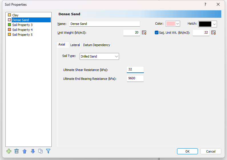
- In the Axial tab set the soil type as the Drilled Sand model, while copying the calculated unit skin resistance and end bearing resistance from the previous tutorial results: 32 and 9600 kPa respectively.
3.2 Edit Boreholes
We will leave the same borehole location and layer thicknesses as in Tutorial 9. To view the borehole details:
- Select Soils > Edit All
 to open the Edit Borehole dialog.
4.0 Piles
4.1 DEFINE PILE SECTION PROPERTIES
The pile is defined similarly as it is in Tutorial 9: Telescopic Drilled Pier with Bell. A minor update must be made to the Pile Section Properties.
- Select Piles > Pile Sections

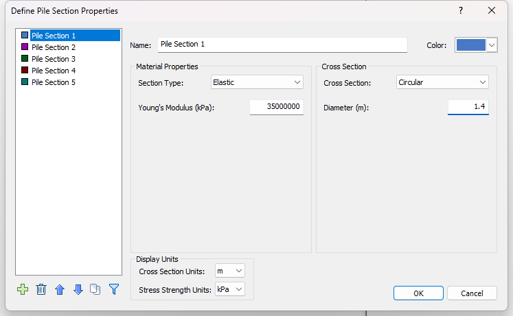
- The section type is chosen as Elastic.
- Change the Young’s modulus to 35000000 kPa for the three segments (Pile Sections 1-3).
- Enter the following Diameter (m) for each pile section (the same diameters entered in Tutorial 9):
- Pile Section 1 = 1.4 m
- Pile Section 2 = 1.2 m
- Pile Section 3 = 1 m
4.2 EDIT PILE TYPE
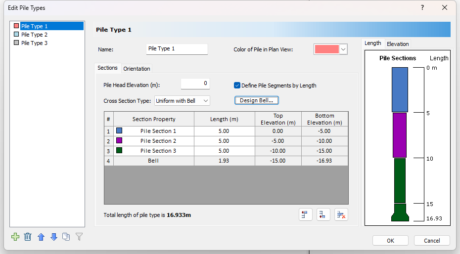
The pile editor will show the same built-up pile definition as in Tutorial 9. To view the Pile Type Editor select Piles > Pile Types.
4.3 EDIT PILE 1
To edit Pile 1:
- In the Plan View, right-click Pile 1 and select Edit Pile, or select Piles > Edit
 and left-click Pile 1.
The Edit Pile dialog will open.
4.3.1 Loading
Next we will apply and define the loading:
- Go to Loading tab and click on the Add
 button to add a Loading Property.
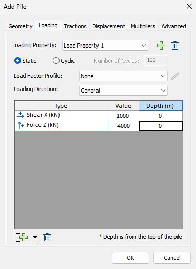
- Enter the follow properties:
- Loading Property = Loading Property 1
- Static
- Load Factor Profile = None
- Loading Direction = General
button at the bottom of the dialog twice to add the following two Load Types:- Force X (kN): Value = 1000 ; Depth (m) = 0
- Force Z (kN): Value = -4000; Depth (m) = 0
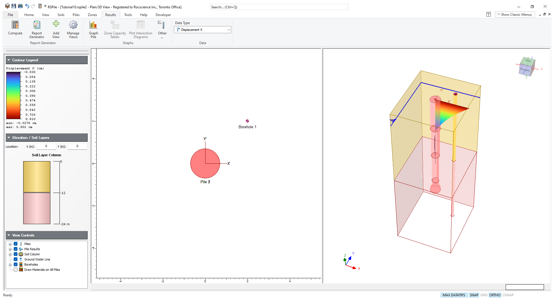
5.0 Results
5.1 COMPUTE
- Select File > Save As to save the file with a new name.
- Then compute the file by selecting Results > Compute

5.2 RESULTS
The results of the pile analysis will be similar to what you have learned in previous tutorial for individual pile analysis.