1 - Quick Start
This tutorial is a simple introductory tutorial that helps you become familiar with the basic modeling and data interpretation features of RocPlane.
An essential part of your rock slope analysis toolkit, RocPlane is an easy-to-use tool for planar wedge stability analysis and design. RocPlane is an especially useful tool for geotechnical engineers analyzing bench stability in open pit mines and rock slopes.
Topics Covered in this Tutorial:
- Project Settings
- Input Data
- Views and viewing options
- Info Viewer
- Exporting Images
Finished Product:
The finished product of this tutorial can be found in the Tutorial 1 Quick Start.pln4 file, located in the Examples > Tutorials folder in your RocPlane installation folder.
1.0 Creating a New File
If you have not already done so, run the RocPlane program by double-clicking the RocPlane icon in your installation folder or by selecting Programs > Rocscience > RocPlane > RocPlane in the Windows Start menu.
When the program starts, a default model is automatically created. If you do NOT see a model on your screen:
- Select: File > New

Whenever a new file is created, the default input data forms a valid wedge, as shown in the image below.
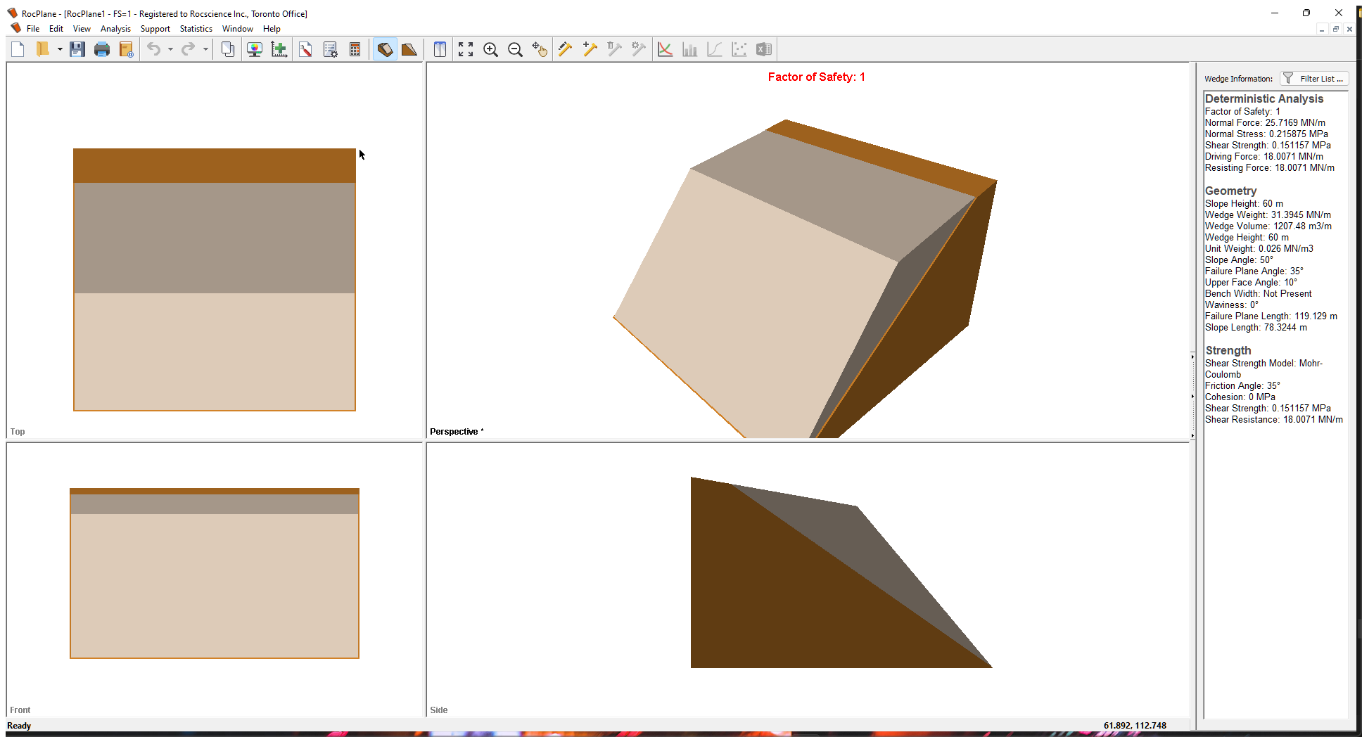
If the RocPlane application window is not already maximized, maximize it now so that the full screen is available for viewing the model.
Notice the four-pane, split screen format of the display, which shows Top, Front, Side and Perspective views of the model. This view is referred to as the 3D Wedge View. The Top, Front and Side views are orthogonal with respect to each other i.e., viewing angles differ by 90 degrees.
Before we proceed, it is very important to note the following:
- Although RocPlane displays the model in a three dimensional format, the RocPlane analysis is strictly a two-dimensional analysis. The 3D display is solely for the purpose of improved visualization of the problem geometry.
- All input data assumes that the problem is uniform in the direction perpendicular to the wedge cross-section. The analysis is performed on a “slice” through the cross-section of unit width.
- All analysis results (e.g., Wedge Weight, Wedge Volume, Normal Force, Resisting Force, Driving Force, etc.) and input data are therefore stated in terms of force per unit length, volume per unit length, etc.
2.0 Project Settings
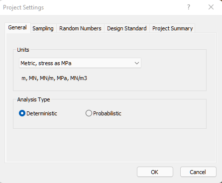
The Project Settings dialog allows you to configure the main analysis parameters for your model, such as Analysis Type and Units. To open the dialog:
- Select Analysis > Project Settings
 in the menu.
2.1 UNITS
The Units setting determines the length and force units used in the analysis. In this tutorial we are using metric MPa units, so make sure the Metric, stress as MPa option is selected for Units in the Project Settings General tab default setting.
2.2 ANALYSIS TYPE
There are two analysis types in RocPlane: Deterministic and Probabilistic. Deterministic is the default.
- A Deterministic analysis assumes that all input parameters are exactly known. RocPlane computes the Factor of Safety for a single wedge. This tutorial demonstrates a Deterministic analysis.
- For a Probabilistic analysis, statistical input data can be entered to account for uncertainty in input data. The result is a distribution of Factors of Safety, from which a Probability of Failure is calculated. Probabilistic analysis is demonstrated in Tutorial 03 - Probabilistic Analysis in RocPlane.
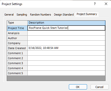
2.3 PROJECT SUMMARY
- Select the Project Summary tab.
- Enter RocPlane Quick Start Tutorial as the Project Title.
 You can have Project Summary information appear on analysis results printouts by setting up a header or footer by selecting File > Page Setup in the menu.
TIP: To have Author and Company information appear by default in Project Summary for new files, you can set them up in the Preferences dialog through the File menu.
- Leave all other settings as is and click OK to close the Project Settings dialog.
3.0 Input Data
Now let’s see what input data was used to create this model. Input data is entered through the Input Data dialog. To open the dialog:
- Select Analysis > Input Data
 in the menu.
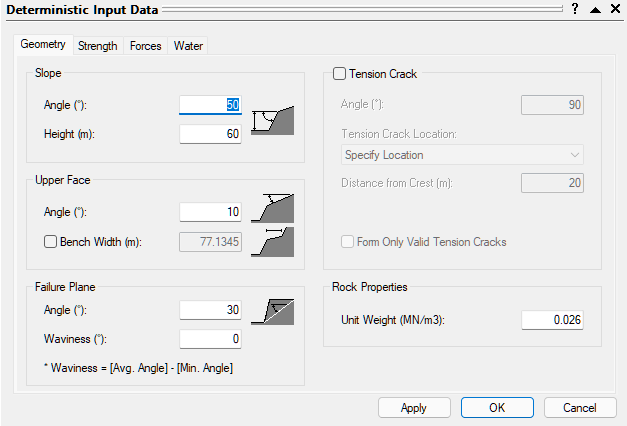
The Geometry input data that you see in this dialog is the default input data, which forms a valid default wedge each time a new file is created.
- Examine the input data in the dialog but don't change any values. We'll come back to this shortly.
- Click Cancel to close the dialog and leave the values as is.
4.0 3D Wedge View
The 3D Wedge View is displayed by default when you create or open a RocPlane file. The view provides a three-dimensional Perspective View of the RocPlane model as well as three orthogonal views (Top / Front / Side) in a four-pane split-screen format.
While in the view, you can use the mouse buttons to interactively manipulate the view as follows:
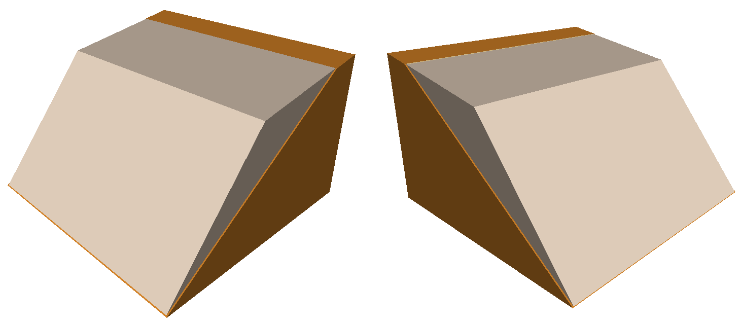
- The Perspective View of the model allows the model to be rotated for viewing at any angle with the left mouse button.
- The wedge can be moved out of the slope with the left mouse button (or the mouse wheel) in any of the four views.
4.1 ROTATING THE MODEL
- Press and hold the left mouse button anywhere off the model in the Perspective View.
The cursor changes to a circular arrow symbol to indicate that you can rotate the model.
 - Keep the left mouse button pressed and move the cursor around.
The model is rotated according to the direction of movement of the cursor. - To exit the rotation mode, release the left mouse button.
The cursor reverts to the normal arrow. - Repeat the above steps to rotate the model for viewing at any angle.
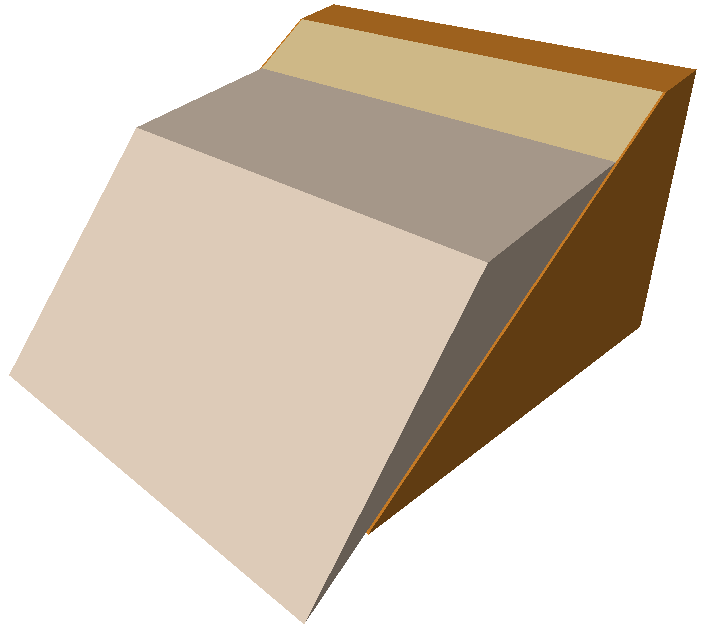
4.2 MOVING THE WEDGE OUT OF THE SLOPE
- Position the cursor over the wedge in any of the views.
The cursor changes to a vertical, two-way arrow symbol .
. - Click and hold the left mouse button and drag the mouse.
As you move the cursor up or down, the wedge slides up or down out of the slope.
NOTES:
- If your model does NOT have a Tension Crack, the wedge slides up or down along the Failure Plane.
- If your model has a Tension Crack, the wedge slides down along the Failure Plane, and up along the Tension Crack.
You can also move the wedge by rotating the mouse wheel while holding down the SHIFT key on the keyboard.
- To move the wedge upwards, rotate the mouse wheel forward.
- To move the wedge downwards, rotate the mouse wheel backwards.
4.3 RESETTING THE WEDGE
To reset the wedge in its normal position, right-click the mouse in any of the four views and select Reset Wedge Movement or Reset View from the popup menu. The wedge snaps back to its normal position. Reset View also resets zooming and rotation.
4.4 RESIZING THE VIEWS
You can change the relative size of the Top / Front / Side / Perspective Views as follows:
Maximize a Pane
- To quickly maximize any pane, double-click inside it.
- To restore the four-pane view, double-click again.
Resize the Panes
- Mouse over any of the vertical or horizontal dividers between the panes or over the intersection point of the dividers.
The cursor changes to a parallel or four-arrow symbol. - Press and hold the mouse, then drag to re-size the panes as desired.
4.5 ZOOM AND PAN
Individual views can be zoomed in or out using the PAGE UP/PAGE DOWN keys, the + or – numeric keypad keys, the F4 / F5 function keys, or the Zoom 
 options On the toolbar. To zoom all views simultaneously, hold down the SHIFT key while using the zoom options. To pan the model, select Pan
  ON the toolbar or press and hold the mouse wheel.
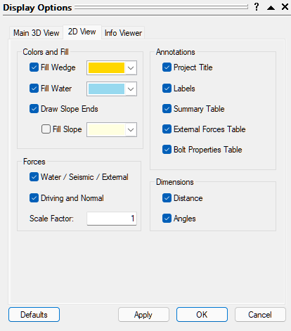
4.6 DISPLAY OPTIONS
You can change the appearance of the 3D Wedge View, the 2D Wedge View, and the Info Viewer using the Display Options dialog. To open the dialog:
- Select View > Display Options
 in the menu.
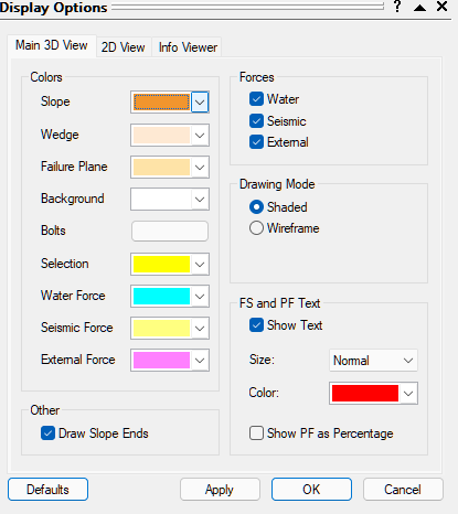
- Click Apply to apply changes and keep the dialog open.
- Minimize/Maximize the dialog using the

 arrows in the upper-right corner.
 - Click Defaults to restore the original program settings.
- Click Close to close the dialog.
5.0 2D Wedge View
The 2D Wedge View in RocPlane allows you to display a two-dimensional view of your model. The view displays model lengths and angles, applied and resultant forces, and tables of analysis results and input data. To display the 2D Wedge View:
- Select Analysis > 2D View
 in the menu.
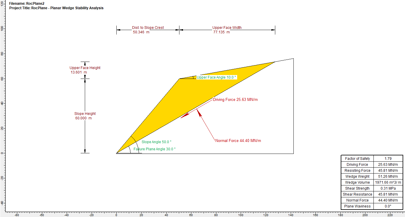
5.1 DISPLAY OPTIONS
You can also use the Display Options dialog to change the appearance of the 2D Wedge View.
TIP: You can also open the Display Options dialog by right-clicking on the view and selecting Display Options on the popup menu.
5.2 ZOOMING
The wedge model can be zoomed in the 2D Wedge View in a variety of ways:
- Rotate the mouse wheel to zoom in or out
- Select the Zoom options in the toolbar
- Use the F2, F4, and F5 function keys
5.3 PANNING
To pan the wedge model in the 2D Wedge View left, right, up, and down, use the arrow keys on the keyboard or click and hold the mouse wheel down while dragging.
6.0 Changing the Input Data and Re-calculating the Safety Factor
We'll now return to the Input Data dialog to change the input data and see how it affects the Factor of Safety.
- Return to the 3D Wedge View by clicking the X in the upper-right corner of the 2D Wedge View or selecting 3D View
 on the toolbar or Main 3D View on the Analysis menu.
 - To open the Input Data dialog, select Analysis > Input Data in the menu or click on the icon in the toolbar
Let’s first decrease the Angle of the Failure Plane:
- Set Failure Plane Angle (deg) = 30.
- Click Apply.
Note that the Safety Factor is automatically re-calculated as 1.2128. - Click the arrow in the upper-right corner of the dialog to minimize it.
6.1 MORE ABOUT THE INPUT DATA DIALOG
Before we proceed, let's look at some of the properties of the Input Data dialog. As you may have noticed, the dialog works a little bit differently than a regular dialog.
- It's known as a "roll-up" dialog since it can be "rolled up" (minimized) or "rolled down" (maximized) by using the arrows in the upper-right corner. You can also minimize/maximize the dialog by double-clicking the mouse.

- The dialog can be left up on the screen while you perform other tasks. When you don't need it, you can minimize it and drag it out of the way.
- If multiple files are open, the data displayed in the dialog corresponds to the active file.
- You can click the Apply button to re-compute results based on changed input data without closing the dialog.
- You can also open the dialog using the F3 shortcut key.
6.2 STRENGTH
Let's now change the shear strength of the failure plane.
- Select the Strength tab.
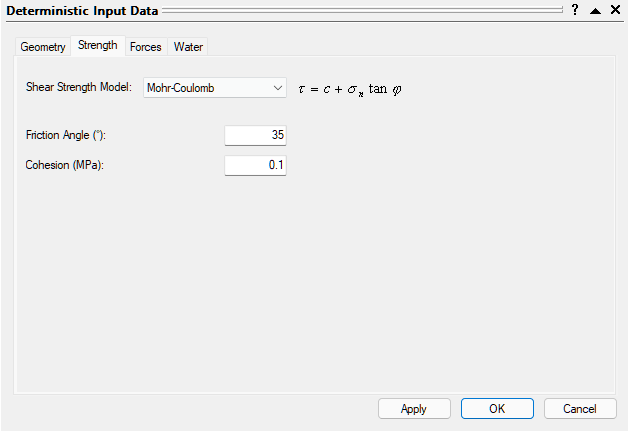
- Set Cohesion (MPa) = 0.1.
- Click Apply.
Note that the Safety Factor increases to 1.78709.
Several different Shear Strength Models are available for selection in the Strength tab. For more information, see Failure Shear Strength Properties in RocPlane.
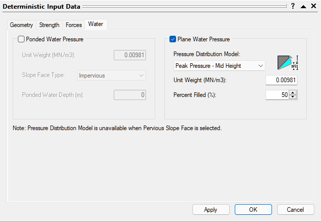
6.3 WATER PRESSURE
By default, Water Pressure is NOT applied to a RocPlane model and the analysis therefore applies to a DRY slope.
To include Water Pressure in the analysis:
- Select the Water tab in the Input Data dialog.
- Select the Plane Water Pressure check box.
Various Pressure Distribution Models are available for selection:
- Peak Pressure Mid Height
- Peak Pressure at Toe
- Peak Pressure at Tension Crack Base
- Custom Pressure
Note that the Safety Factor decreases to 1.06123. This indicates the wedge is marginally stable for the given Water Pressure and Strength conditions
The Safety Factor increases to 1.60563.
arrow).Notice that the water level in the slope is indicated by blue shading. Since we entered Percent Filled = 50%, the lower half of the Failure Plane is shaded blue.
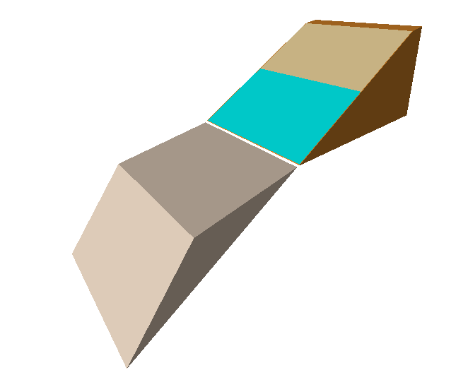
Also notice that, if you rotate the model in the Perspective View (click and drag the left mouse button), a blue arrow representing the Water Pressure force is displayed normal to the Failure Plane on the underside of the wedge.
6.4 SEISMIC FORCE
Now we'll include Seismic Force in the analysis.
- In the Input Data Forces tab, select the Seismic Force check box.
- Set Seismic Coefficient = 0.2.
- Click Apply.
Note that the Safety Factor drops to 1.08851.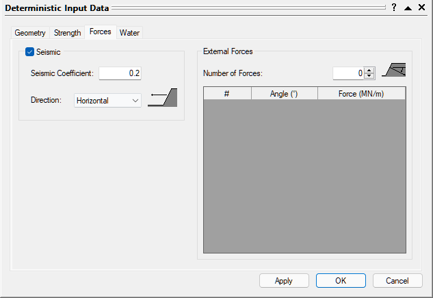
Also note that an arrow representing the Seismic Force is now displayed on the model.
The Seismic Force applied to the wedge is F = 0.2 * m * g, where g = acceleration due to gravity and m = mass of the wedge (per unit width of the slope cross-section). - Remove the Seismic Force from the model by deselecting the Seismic check box.
- Click Apply.
6.5 TENSION CRACK
Let’s now add a Tension Crack to the model.
- Select the Geometry tab.
- Select the Tension Crack option.
- Click Apply.
The Safety Factor is now 1.47839.
Notice that the wedge now appears quite different. We used the Minimum FS Location option for the Tension Crack. This means that RocPlane automatically determines the location of the Tension Crack that produces the Minimum Safety Factor. Also note that the Tension Crack is formed near the crest of the slope.
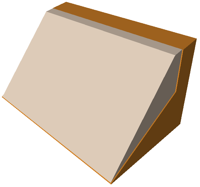
In this case, the Minimum Safety Factor results when the Tension Crack is located about 7.1 meters from the crest of the slope.
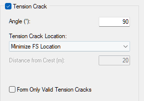
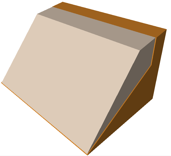
Now let’s use the Specify Location option, which allows you to specify the location of the Tension Crack, as measured horizontally from the crest of the slope.
- Select the Specify Location option for the Tension Crack.
- Distance From Crest (m) = 20.
- Click OK.
The Tension Crack is now located 20 meters behind the crest of the slope, as shown in the figure below. In this case, changing the Tension Crack location did not change the Safety Factor significantly (FS = 1.48482).
7.0 Info Viewer
Now let's take a look at the RocPlane Info Viewer. To open the Info Viewer:
- Select Analysis > Info Viewer
 in the menu.
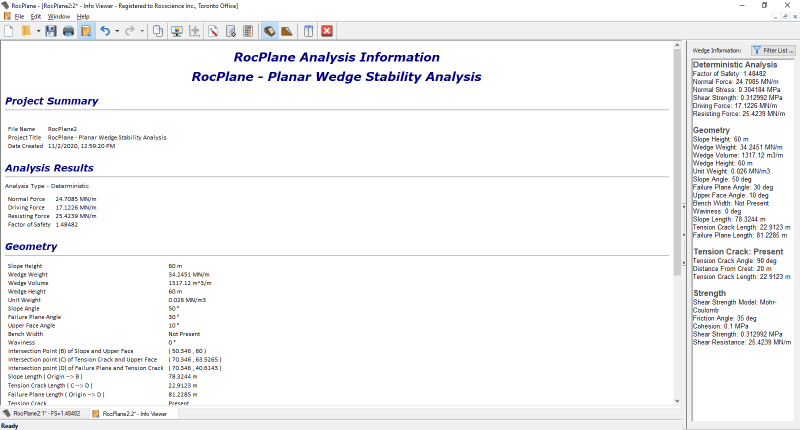
The Info Viewer provides a comprehensive summary of model input data and analysis results in an easy-to-follow text listing. Use the scroll bar or the mouse wheel to scroll through the information. The Info Viewer behaves like any other view in RocPlane (i.e., it can be re-sized, tiled, minimized, maximized, and closed). For more help, see RocPlane Info Viewer.
8.0 Exporting Images
RocPlane has various options for exporting image files.
8.1 EXPORT IMAGE FILE
The Export Image File option in the File menu allows you to save the current to one of the following image file formats:
- JPEG (*.jpg)
- Windows Bitmap (*.bmp)
- PNG
- GIF
- EMF
- WMF
8.2 COPY TO CLIPBOARD
You can also copy the current view to the Windows Clipboard using the Copy option on the toolbar, the Edit menu, or the right-click menu. This copies the current view to the Clipboard as a bitmap image that can be pasted into word or image processing applications.
TIP: To capture the entire application window to the clipboard, use the ALT+PrintScreen keyboard combination. This is useful if you have multiple tiled views on the screen or you want to capture all four views of the 3D Wedge View.
That concludes the tutorial. You are now ready for the next tutorial, Sensitivity Analysis in RocPlane.