5 - Slope Design with Eurocode 7
This tutorial describes how to design a slope to Eurocode 7 specifications using RocPlane. The focus is on how different design combinations are applied in the computation and what they mean.
Topics Covered in this Tutorial:
- Example for Design Approach 1, Combination 2
- Example for Design Approach 2
- Single Source Principle
Finished Product:
The finished model can be found in the Tutorial 5 Eurocode Design.pln4 data file. All tutorial files installed with RocPlane can be accessed from the RocPlane installation folder.
1.0 Introduction
Eurocode 7 is a design document that establishes rules and standards for geotechnical engineering design across Europe (BSI, 2004). Eurocode 7 represents a major change in design philosophy. Traditionally a single, lumped Factor of Safety accounts for all of the uncertainties in the problem. With Eurocode 7, partial Factors of Safety are applied to different components of the analysis. The partial factors are applied prior to the analysis to give design values that are used in the calculation. The final result is an over-design factor, which must be greater than 1 to ensure the serviceability limit state requirement is satisfied. For more information on using Eurocode 7 in geotechnical design, see Smith (2006) and Bond and Harris (2008) in the tutorial's References.
2.0 Creating a New File
If you have not already done so, run the RocPlane program by double-clicking the RocPlane icon in your installation folder or by selecting Programs > Rocscience > RocPlane > RocPlane in the Windows Start menu.
When the program starts, a default model is automatically created. If you do NOT see a model on your screen:
- Select File > New

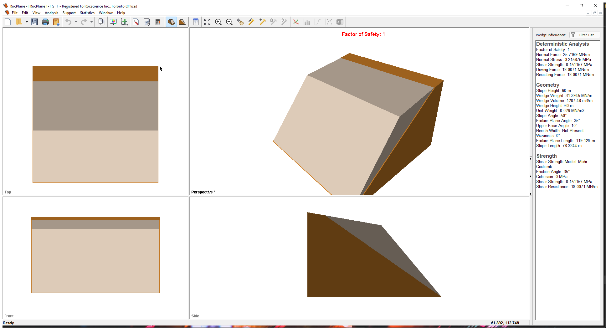
Whenever a new file is created, the default input data forms a valid wedge, as shown in the image below.
If the RocPlane application window is not already maximized, maximize it now so that the full screen is available for viewing the model.
Notice the four-pane, split screen format of the display, which shows Top, Front, Side and Perspective views of the model. This view is referred to as the 3D Wedge View. The Top, Front and Side views are orthogonal with respect to each other i.e., viewing angles differ by 90 degrees.
Before we proceed, it is very important to note the following:
- Although RocPlane displays the model in a three dimensional format, the RocPlane analysis is strictly a two-dimensional analysis. The 3D display is solely for the purpose of improved visualization of the problem geometry.
- All input data assumes that the problem is uniform in the direction perpendicular to the wedge cross-section. The analysis is performed on a “slice” through the cross-section of unit width.
- All analysis results (e.g., Wedge Weight, Wedge Volume, Normal Force, Resisting Force, Driving Force, etc.) and input data are therefore stated in terms of force per unit length, volume per unit length, etc.
3.0 Model
3.1 PROJECT SETTINGS
The Project Settings dialog allows you to configure the main analysis settings for your model. To open the dialog:
- Select Analysis > Project Settings

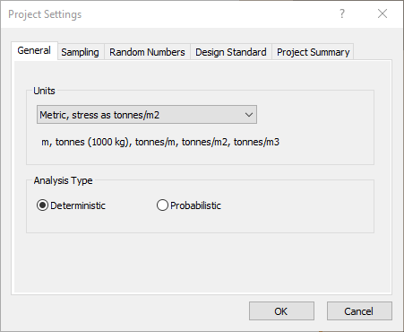
- In the General tab, set Units = Metric, stress as MPa Units.
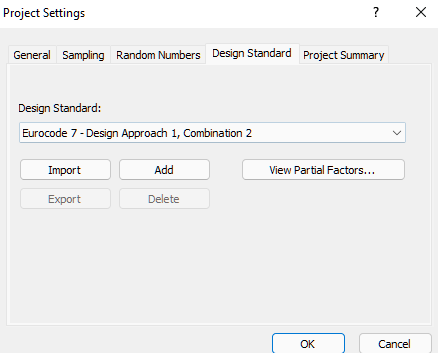
- Select the Design Standard tab in the dialog.
You’ll see that the current Design Standard is None.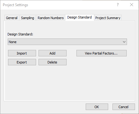
Leave this setting as is. We'll come back later to assign different design standards.
- Select View Partial Factors.
With no design standard applied, you should see that all Partial Factors are set to a default of 1, which means all values used in the calculation are the exact input values.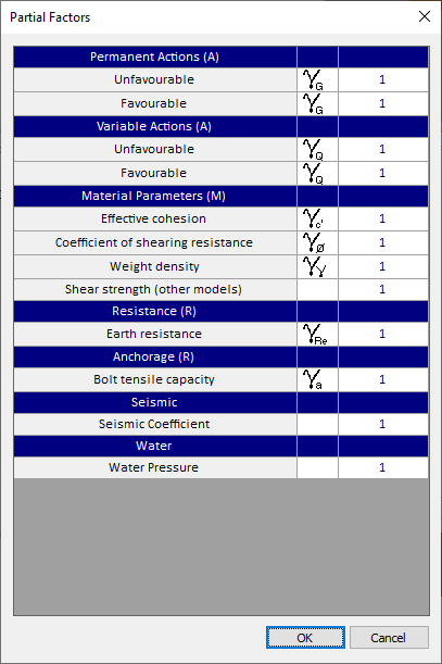
- Select Cancel to close the Partial Factors dialog.
- Select OK to close the Project Settings dialog.
3.2 INPUT DATA
Let’s use the default Input Data for this example. The default model has a Factor of Safety of 1.0.
3.3 BOLT PROPERTIES
Let’s add a Bolt Property using the Bolt Properties dialog. To open the dialog:
- Select Support > Bolt Properties

- Change Bolt Property 1 Type to Simple Bolt Force.
- Set Bolt Model = Active.
- Enter a Force value of 1 MN/m.
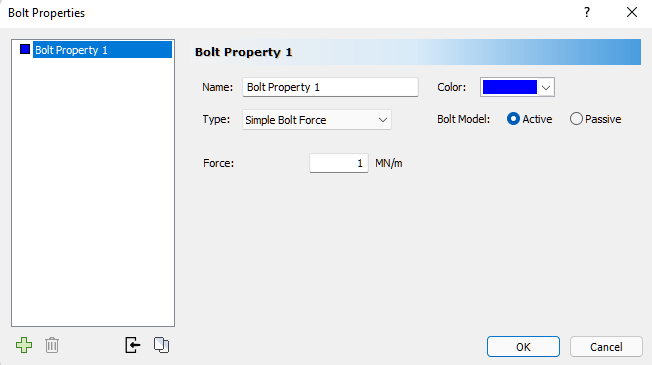
- Click OK to save changes.
3.4 ADD BOLT
Next, let's add a bolt to the model using the Bolt Property we just set up. Bolts are added using the Add Spot Bolt dialog. To open the dialog:
- Select Support > Add Spot Bolt

- Move the cursor into the Top, Front, or Perspective View.
Notice that the cursor changes to an arrow / rockbolt icon. As you move the cursor over the wedge, notice that the rockbolt and arrow now line up. This indicates that you may add the bolt to the wedge. - Click at the point on the wedge where you want the bolt installed.
The Add Spot Bolt dialog appears on the screen, which allows you to modify the bolt orientation and other properties. - Make sure Bolt Property 1 is selected and enter the following specifications.
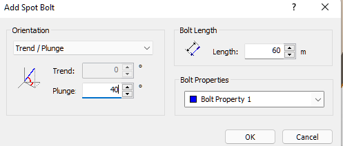
- Click OK to add the bolt to the model.
The Factor of Safety is now 1.053.
4.0 Design Approach 1, Combination 2
Without changing the current input data, let’s go back to the Project Settings dialog to apply a design standard. To learn more about the Design Standard option, see Design Standard Setting in RocPlane.
- Select Analysis > Project Settings
- Select the Design Standard tab.
- Select Eurocode 7 – Design Approach 1, Combination 2 for the Design Standard.
- To view the Partial Factors for this Design Standard, click the View Partial Factors button.
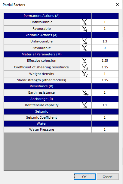
Applying this set of Partial Factors results in the enlargement of unfavourable variable actions while ignoring favourable actions, as well as reducing the shear strength parameters. If bolts are present, their capacity or the resistance they provide to stabilize the slope is also reduced. - Click OK in the Partial Factors dialog.
- Click OK in the Project Settings dialog.
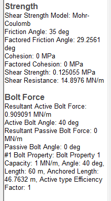
The wedge should now have a Factor of Safety of 0.838. Notice the Strength and Bolt Force information listed in the Sidebar Wedge Information Panel.
4.1 EQUIVALENT MODEL
We can reproduce the results from Design Standard Approach 1, Combination 2, without having to use the Design Standard. Let’s first turn off the Design Standard.
- Re-open the Project Settings dialog and, under the Design Standard tab, change the Design Standard to None.
Note that the Factor of Safety has gone back to 1.053.
To simulate the design approach, we need to apply factors as follows:
- Increase variable unfavorable actions by a factor of 1.3. Because there are no external variable loads, we do not need to make any changes.
- Reduce the effective cohesion and the friction angle (tan(φ)) by a factor of 1.25.
- Go to the Input Data
 dialog and in the Strength tab, change Frictional Angle (deg) to 29.256°.
Reduced Phi:
Tan -1(Tan(35°)/1.25) = 29.256° - Click Apply.
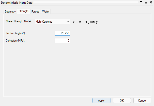
- Click OK to close the Input Data dialog.
Next, we need to reduce the Tensile Capacity of all bolts. We do this through the Bolt Properties dialog.
- Select Support > Bolt Properties
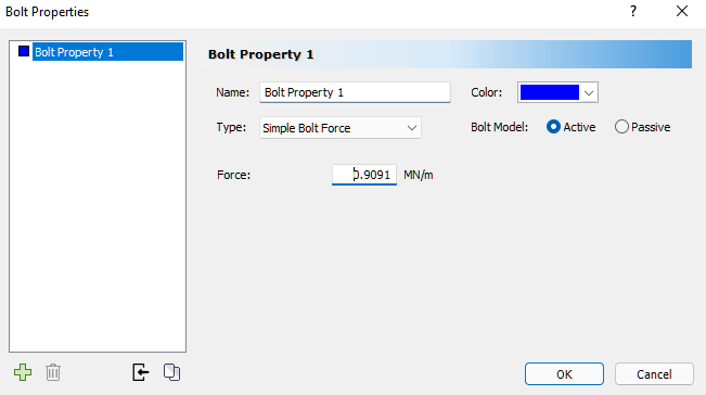
- Change the Force to 0.9091 MN (1MN/1.1=0.9091MN).
The Factor of Safety should now be 0.838, which is exactly the same as that for Design Approach 1, Combination 2.
5.0 Design Approach 2
Next, we'll apply a second Design Standard using the same geometry but removing the bolt.
To delete the bolt:
- Select Delete Bolt
 from the toolbar or Support menu.
 - Place the cursor in the Top, Front, Side, or Perspective View.
The cursor changes to a small box. - Mouse over the bolt you want to delete.
- Click to delete the bolt.
Now, we'll add an external force to the model, using the Input Data dialog. Before proceeding, make sure Design Standard in the Project Settings Design Standard tab is still set to None.
- Re-open the Input Data dialog.
- Select the Strength tab and change Friction Angle back to 35°.
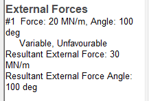
- Select the Forces tab and enter the following data:
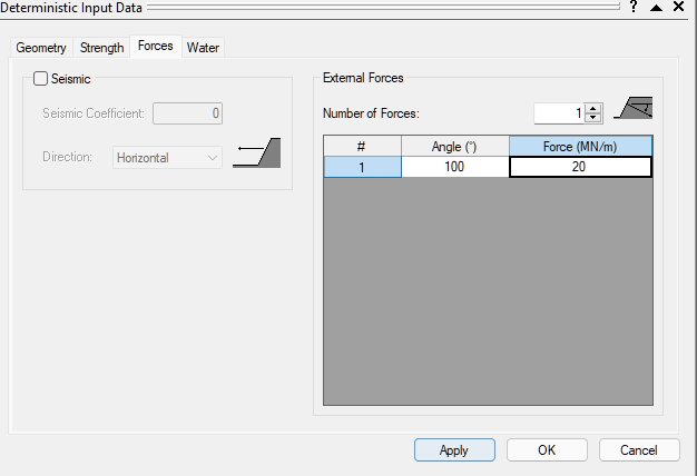
- Click OK to save the changes.
The Factor of Safety should have decreased to 0.868. The direction of the applied load decreases the stability of the wedge.
- Select the Design Standard tab.
- Set the Design Standard to Eurocode 7 - Design Approach 2.
- Click the View Partial Factors button.
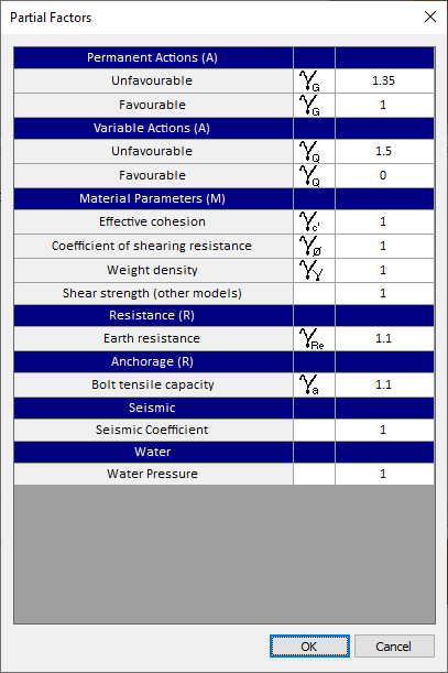
For this Design Standard, a partial factor is applied to the driving force of the slope weight (permanent unfavorable action), any unfavorable external force that is set to be “variable”, the joint shear strength, and the tensile capacity of any bolts. - Click OK in the Partial Factors dialog.
- Click OK in the Project Settings dialog.
Let's now apply the second Design Standard, again using the Project Settings dialog.
The Factor of Safety is now 0.782. Notice the External Forces listing in the Sidebar Wedge Information Panel.
5.1 EQUIVALENT MODEL
We can reproduce the results from Design Standard Approach 2 without having to use the Design Standard. Let’s first turn off the Design Standard.
- Re-open the Project Settings dialog and, under the Design Standard tab, change the Design Standard to None.
The Factor of Safety has gone back to 0.868.
To simulate the design approach, we need to apply changes to the following parameters:
- Under the Slope tab in the Input Data dialog, multiply the Rock Unit Weight by 1.35, to get 0.0351MN/m3. This has the same effect as applying a factor of 1.35 to any permanent unfavorable actions, which in this case is the driving force due to the slope weight. However, remember that the weight has both a favorable and unfavorable action component (stabilizing and driving). We have to adhere to the “Single Source Principle” and apply only 1 factor to any actions that comes from the same source. Click Apply and the factor of safety changes to 0.890.
- Under the Strength tab in the Input Data dialog, we need to reduce the overall joint shear strength by a factor of 1.1. This is the equivalent to reducing the Earth Resistance by a factor of 1.1.
Base Joints Friction Angle = Tan-1(Tan(35°)/1.1) = 32.48°
Keep in mind that this is different than reducing individual shear strength parameters. If cohesion is present, then a factor of 1.1 is applied to the overall shear strength:
Factored Shear Strength = (Normal Force x Tan(φ) + cohesion)/1.1
Click Apply in the Input Data dialog. The Factor of Safety should now be 0.809.
- Under the Forces tab in the Input Data dialog, we need to multiply the value of the external force by 1.5 to get 30MN. We do this because the external force is an Unfavourable Action, and is considered to be Variable.
The Factor of Safety is now 0.782, the same as for Eurocode – Design Approach 2.
6.0 References
Bond, A. J. and Harris, A. J., 2008. Decoding Eurocode 7, Taylor & Francis.
British Standards Institution, 2004. Eurocode 7: Geotechnical design – Part 1: General rules, BS EN 1997-1, London, UK.
Smith, 2006. Smith’s Elements of Soil Mechanics, 8th Edition, Blackwell Publishing.
This concludes the tutorial. You are now ready for the next tutorial, Tutorial 06 - Bench Design in RocPlane.