7 - Preload with Back Analysis
1.0 Introduction
The purpose of this exercise is to determine how to construct a building with a load of 500 lbs/ft2 on normally consolidated medium clay and have it settle less than 4 inches. The way to do this is to apply a layer of fill to compact the clay before constructing the building. We need to determine what thickness of fill will compact the clay enough to ensure that the building settlement is less than 4 inches.
Topics Covered in this Tutorial:
- Pre-Loading
- Consolidation
- Relative Settlement
Finished Product:
The finished product of this tutorial can be found in the Tutorial 07 Preload Back Analysis.s3z file. All tutorial files installed with Settle3 can be accessed by selecting File > Recent Folders > Tutorials Folder from the Settle3 main menu.
2.0 Model Setup
If you have not already done so, run Settle3 by double-clicking on the Settle3 icon in your installation folder. Or from the Start menu, select Programs > Rocscience > Settle3.
2.1 Project Settings
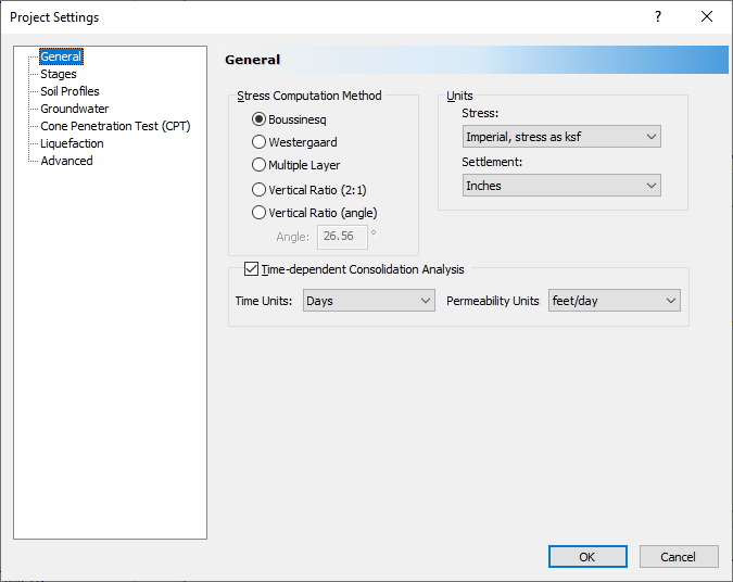
- Select Home > Project Settings
 and make sure the General tab is selected.
 - Set the Stress units = Imperial, stress as ksf, and the Settlement units = Inches.
- Select the Time-dependent consolidation analysis checkbox. A message will appear informing you that the groundwater analysis option will be turned on because it is required for consolidation analysis. Click OK to close the warning.
- Set the Time Units = Days, and the Permeability Units = feet/day.
Click on the Stages tab. Set the Number of Stages = 7, and enter the following names for each stage
#
Time (Days) Name
1 0
Add Preload 2 365 Preload + 1 year 3 366 Remove Preload 4 370
Add Load 5 735 Load + 1 year 6 1100 Load + 2 years 7 2195 Load + 5 years 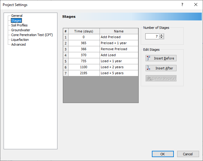
- Select Soil Profile tab, and select the 'Depth below Ground surface' option.
- You may be warned that the unit system has changed. If this is the case, select Yes to reset the unit-dependent values. Click OK to close the dialog.
2.2 Assigning Water Table
- Select Groundwater > Add Piezometric Line
 from the menu.
 - Keep the default value of 0 ft, and click OK.
- Click Select All in the dialog that pops up and click OK.
2.3 Soil Properties
For this tutorial, we will assume a 10-foot layer of medium clay on top of a 20-foot layer of stiffer sandy clay.
- Select Soils > Define Soil Properties

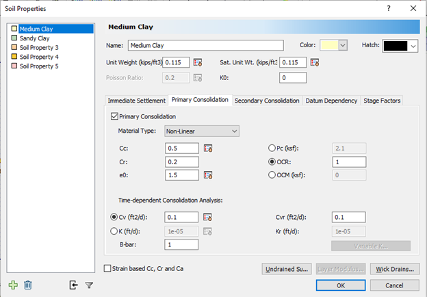
- Change the name of Material 1 to Medium Clay. Set the other parameters as shown:
- Unit Weight (kps/ft3) = 0.115
- Sat. Unit Wt (kps/ft3) = 0.115
- Primary Consolidation = checked
- Material type = Non-Linear
- Cc = 0.5
- Cr = 0.2
- e0 = 1.5
- OCR = 1
- Time-dependent Consolidation Analysis
- Cv (ft2/d) = 0.1
- Cvr (ft2/d) = 0.1
- B-bar = 1
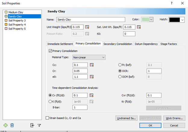
- Unit Weight (kps/ft3) = 0.115
- Sat. Unit Wt (kps/ft3) = 0.115
- K0 = 0
- Primary Consolidation = checked
- Material type = Non-Linear
- Cc = 0.1
- Cr = 0.05
- e0 = 1.1
- OCR = 1
- Time-dependent Consolidation Analysis
- Cv (ft2/d) = 0.1
- Cvr (ft2/d) = 0.1
- B-bar = 1
2.4 Soil Layers
- Select Soils > Layers

- Change the thickness of the first soil layer to 10.
- Click the button for Insert Layer Below.
- Set the thickness of this layer to 20 as shown.
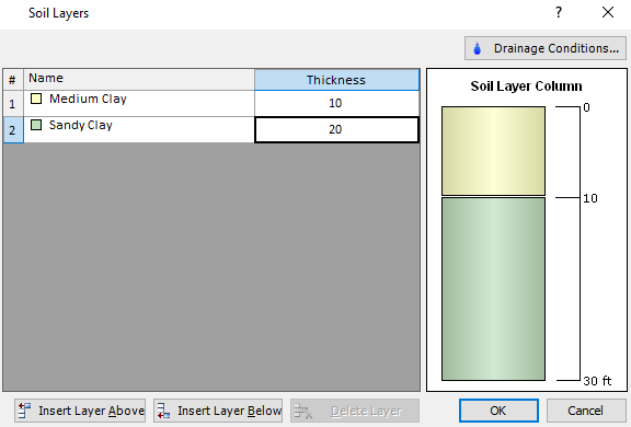
- Click on the Drainage Conditions button, and make sure that the Drained Ground Surface checkbox is selected.
- Click OK to close the dialogs.
2.5 Adding a Preload
The Pre-Load option allows you to determine the required height of material to achieve a specified settlement at a particular stage. Make sure you are viewing Stage 1.
- Select Loads > Pre-Load

- The shape of the preload can be any polygon. For this example, we will define a simple square. Enter the following coordinates:
- {0,0}
- {100,0}
- {100,100}
- {0,100}
- "c" (to close the region)
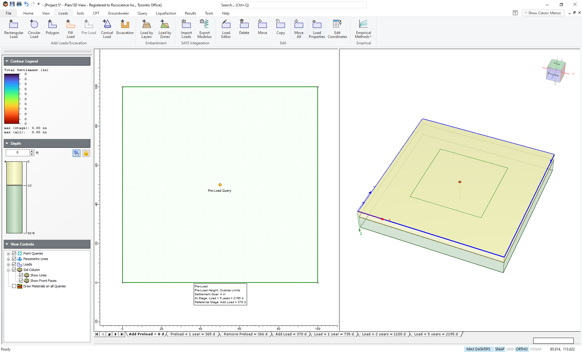
A summary of the preload back analysis results is displayed in a text box in the Plan View.
The summary indicates Preload Height: Outside Limits. Since we haven’t yet added the building load, the program cannot calculate a solution.
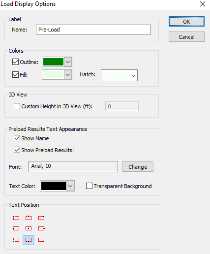
The display of the preload analysis summary text box can be customized as follows:
- Right-click on the preload and select Display Properties from the popup menu.
- You can customize the text size, font, colour and position of the text box. This is left as an optional exercise after completing this tutorial. Select Cancel.
Click through the stages and you will see that the preload is removed at the third stage (366 days).
2.6 Add Load and Preload Height Computation
We will simulate the construction of a building in the fourth stage.
- Click on the Stage tab ‘Add Load = 370 d’.
- Select Loads > Rectangular Load
 from the menu.
 - Set the Length to 75 ft and the Width to 80 ft. Set the magnitude (Pressure) to 0.5 ksf as shown.
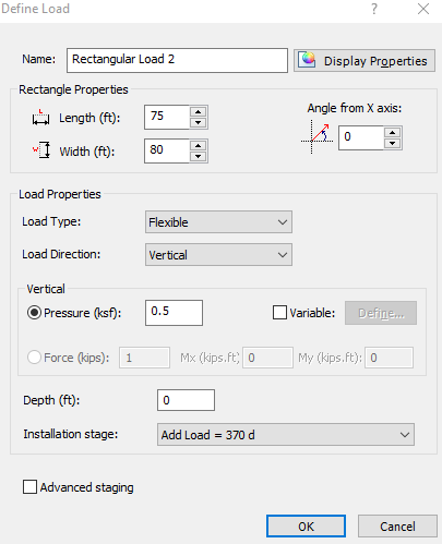 To simplify the modelling we have assumed that the entire building load is added at once. In reality, the building load could be added over a series of intermediate stages.
 - Click OK. You will now see a rectangle that needs to be placed somewhere on the plan view. Click on the existing query point at the center of the preload to center the building load within the preload area.
Settle3 will now automatically compute the height of the preload required to meet the settlement specifications. This may take a few seconds. The model should look as follows:
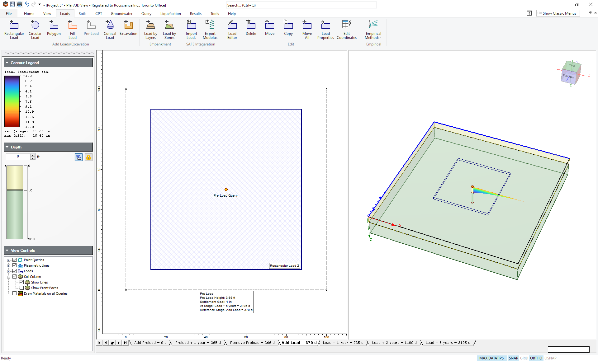
You can see that the pre-load height for a settlement of 4 inches is calculated to be 3.69 feet. You can see under the contour legend on the right that the total settlement at this stage (Add Load = 370 d) is 11.6 inches. If you click the tab for the final stage (Load + 5 years), you will see a settlement of 15.6 inches – exactly 4 inches greater than the settlement when you applied the load.
To double-check this, right-click on the tab for the ‘Add Load’ stage and select Set as Reference Stage. You will now see a settlement relative to this stage. If you go to the final stage you will see a relative settlement of 4 inches.
You may now want to save this model by going to File > Save As, before continuing with the tutorial.
3.0 Further Analysis
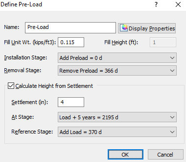
Perhaps 4 inches of settlement is too much for this building. Let’s say your tolerance is only 2 inches. To see if this is possible:
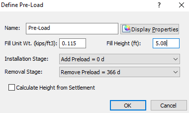
- Right-click on the preload rectangle. You will see the preload dialog again. Notice that the Fill Height calculated from the previous analysis is visible (3.69 ft).
- Change the Settlement to 2 inches as shown:
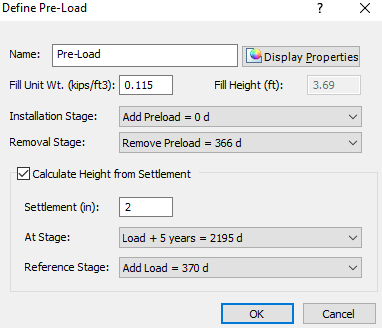
- Click OK.
The program will now recalculate the height of fill required to achieve a building settlement of 2 inches. This may take a few seconds.
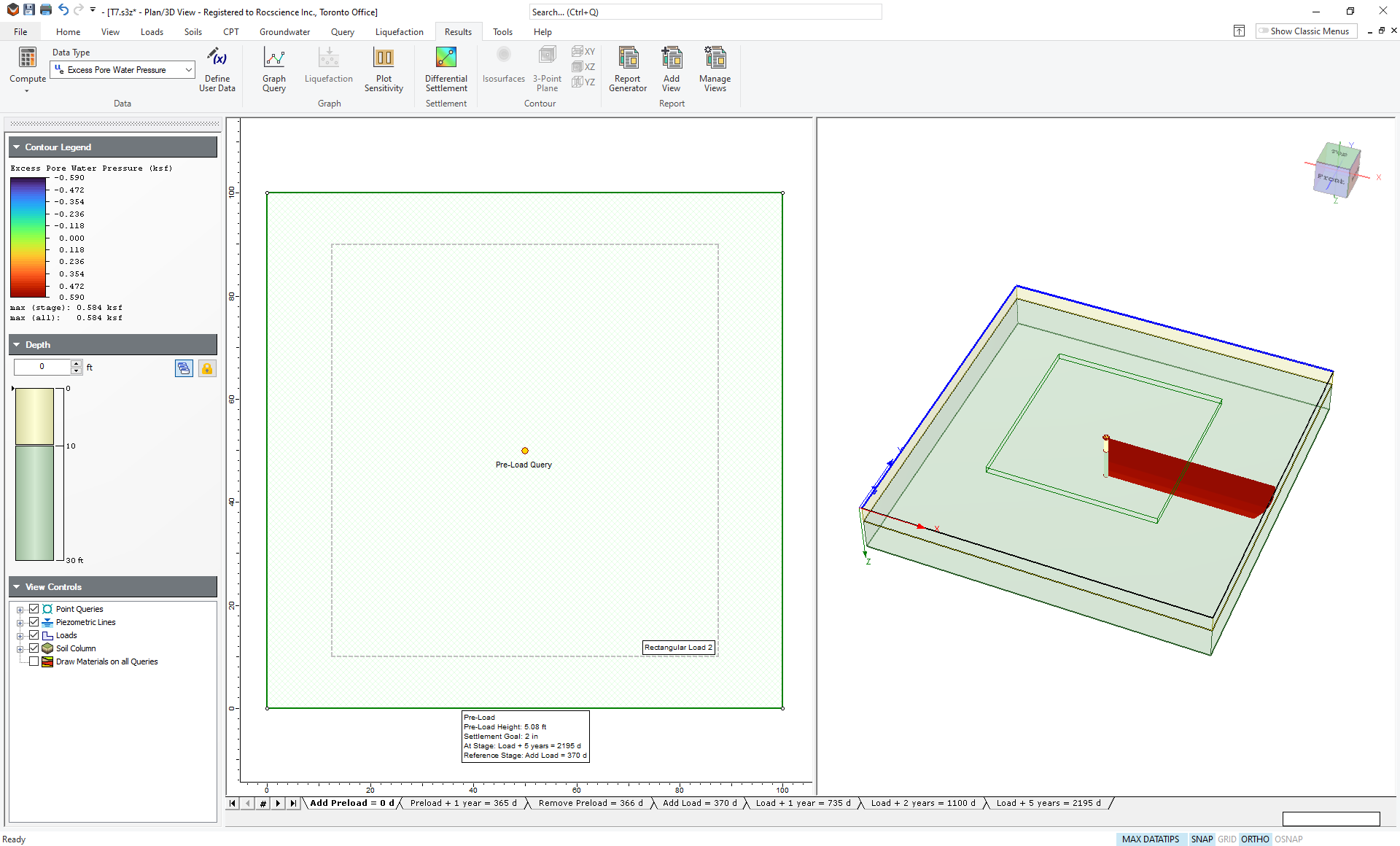
When the calculation is finished, you will see that a preload height of 5.08 feet is required. If you are still looking at the final stage, with the reference stage set to ‘Add Load = 370 d’, then you should see a relative settlement of 2.00 in.
3.1 Excess Pore Pressures
- Right-click on any stage tab and select Reset Reference Stage.
- Go to the Results tab and change the plot to show Excess Pore Water Pressure using the drop down menu of data types.
- Click on the tab for the first stage (Add Preload = 0 d). You will see a large jump in excess pore pressure at this stage when the load is applied.
- Now click on the next stage (Preload + 1 year). You will see that the excess pore pressure has decreased, but it is not 0.
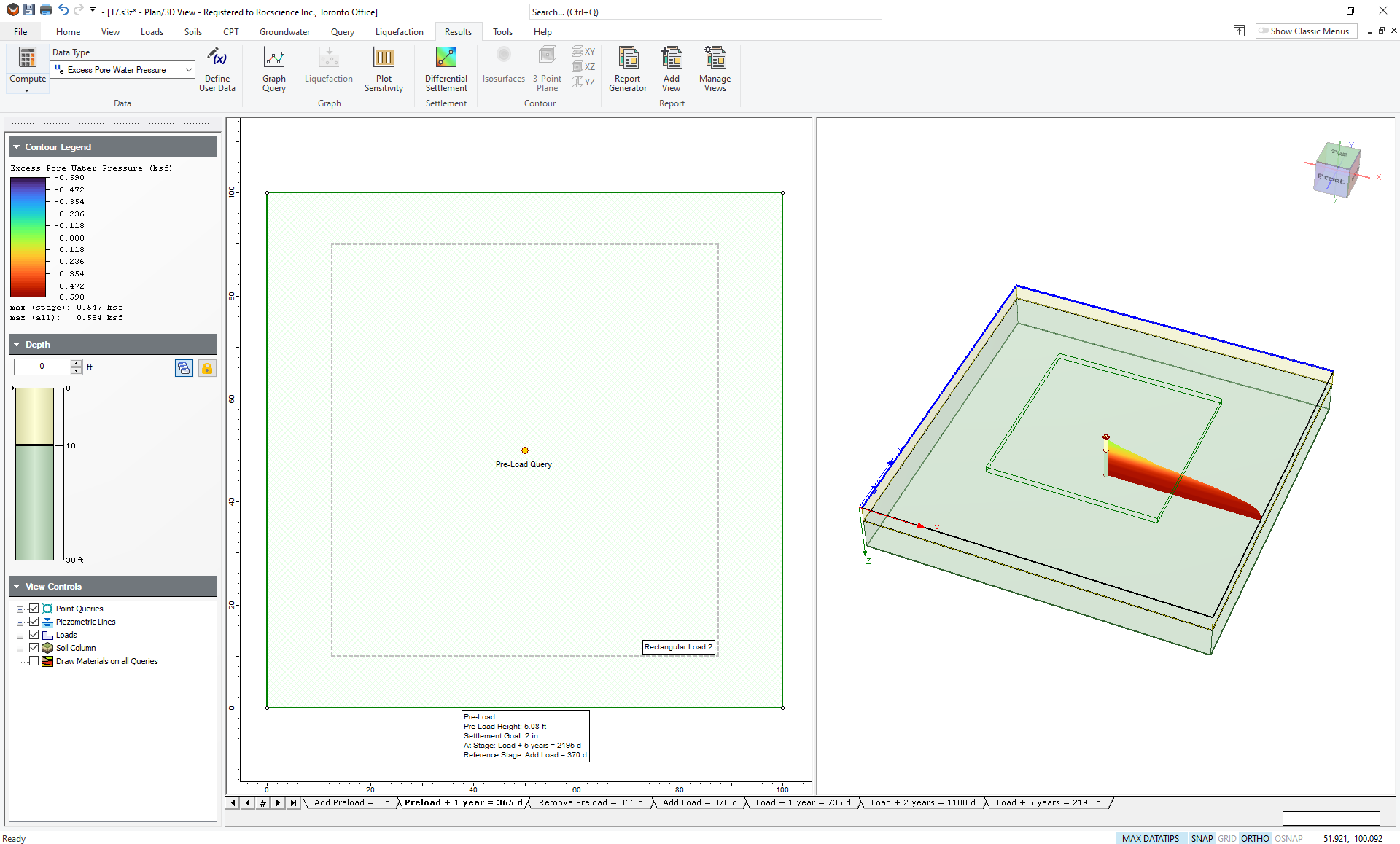
This indicates that the soil has not finished consolidating when the preload is about to be removed one day later. If the soil was completely consolidated before removing the preload, less preload would be required to reach the same desired settlement.
You can simulate this by either allowing more time before removing the preload or by adding wick drains to speed up the consolidation process (see Tutorial 06 Preload with Wick Drains). This is left as an additional exercise.
3.2 User-Defined Preload Height
The Preload option can also be used to directly define the height of the fill material, without using the back analysis capability. Simply clear the Calculate Height from Settlement checkbox in the Define Preload dialog, and you can enter a value of fill height. If you had previously carried out a back analysis (as described in this tutorial) the computed fill height will automatically be entered. If you no longer require the back analysis feature, you may wish to turn this checkbox off to avoid unnecessary calculation and the display of the back analysis results in the Plan View.
This is left as an additional exercise.
This concludes the tutorial. You may now exit the Settle3 program.