25 - Ground Improvement – Pt 3: Dynamic Compaction
1.0 Introduction
This tutorial demonstrates the Dynamic Compaction method of the Ground Improvement feature in Settle3.
Topics Covered in this Tutorial:
- Adding a Dynamic Compaction to a Ground Improvement Region
Finished Product:
The finished product of this tutorial can be found in the Tutorial 25 Ground Improvement with Dynamic Compaction.s3z file. All tutorial files installed with Settle3 can be accessed by selecting File > Recent Folders > Tutorials Folder from the Settle3 main menu.
1.1 Model Description
The model will consist of a 5m high embankment resting on a 1m thick fine-grained soil covering overlying landfill material. The base width of the embankment is 45m and the angles of the left and right sides are both 45deg.
2.0 Model
2.1 Project Settings
- Select Home > Project Settings

- In the General tab, set the Stress units to Metric, stress as tonnes/m2
- In the Stages tab, set the Number of Stages to 6 and rename the first stage to Before Embankment.
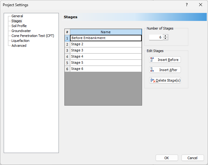
- Click OK.
2.2 Soil Properties
- Select Soils > Define Soil Properties

- Uncheck Primary Consolidation for Soil Property 1 and Soil Property 2.
- Enable Immediate Settlement for Soil Property 1 and Soil Property 2.
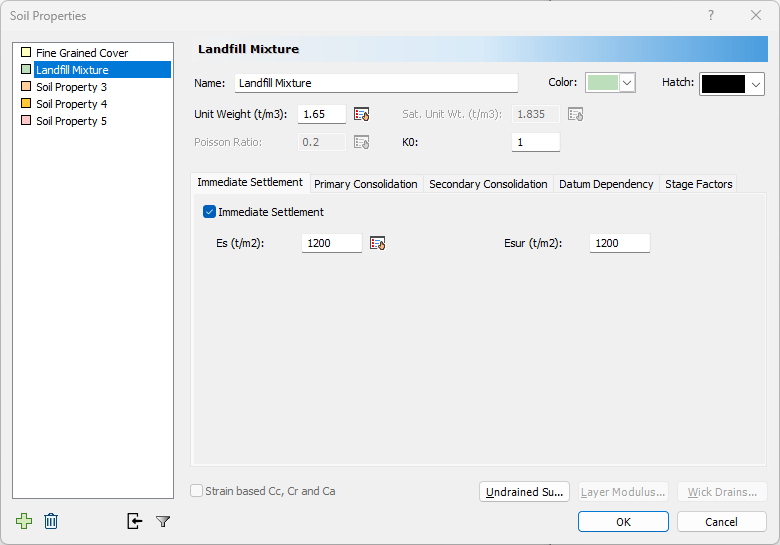
Enter the following soil properties:
Name Unit Weight (kN/m3) Poisson's Ratio K0 Es (t/m2) Esur (t/m2) Fine Grained Cover 1.35 0.2 1 1000 1000 Landfill Mixture 1.65 0.2 1 1200 1200 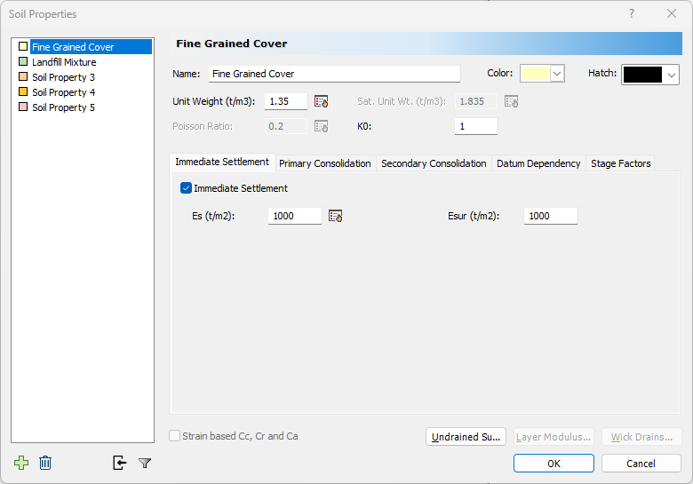
- Click OK.
2.3 Soil Layers
- Select Soils > Layers

- Click Insert Layer Below
 to add a new layer to the model.
 - Set the Soil property of the first layer to Fine Grained Cover with a thickness of 1m.
- Set the Soil property of the second layer to Landfill Mixture with a thickness of 19m.
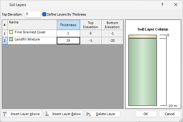
- Click OK.
3.0 Embankment Load
- Select Loads > Load by Layers

- Change the Number of Layers to 5.
- Set the Base Width to 50m.
Enter the following properties for the embankment load:
Layer Stage Left Bench Width (m) Left Angle (deg) Height (m) Unit Weight (tonnes/m3) Right Angle (deg) Right Bench Width (m) 1 2 0 45 1 1.835 45 0 2 3 0 45 1 1.835 45 0 3 4 0 45 1 1.835 45 0 4 5 0 45 1 1.835 45 0 5 6 0 45 1 1.835 45 0 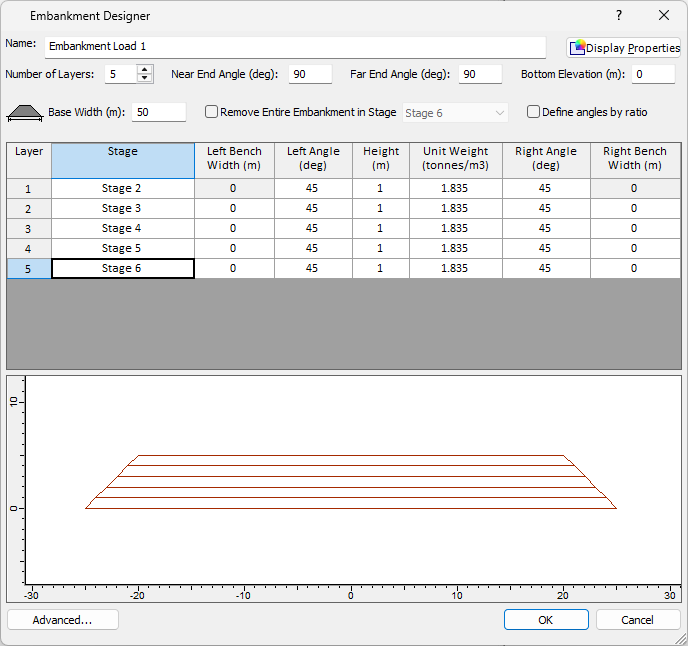
- Click OK.
3.1 Pick Near/Far Points
In the command prompt in the bottom right of the screen:
- Set (12.5, -50) as the near point. Press ENTER.

- Set (12.5, 50) as the far point. Press ENTER.

4.0 Results Before Improvement
4.1 Field Point Grid
- Select Query > Auto Field

- Change Autogrid Expansion Factor to 1.
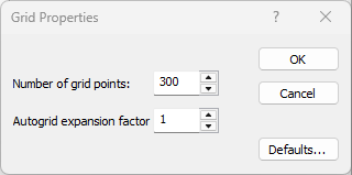
- Click OK.
4.2 Query Line
- Select Query > Add Line

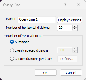
- Click OK.
- In the Command Prompt, set the first point of the query line to (12.5, -50). Press ENTER.

- Set the second point of the query line to (12.5, 50). Press ENTER.

4.3 Query Point
- Select Query > Add Point

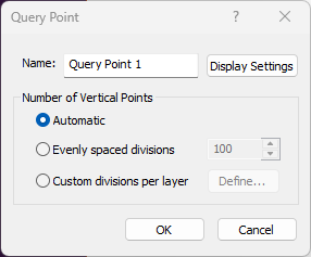
- Click OK.
- Place the query at (12.5, 0).
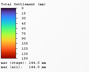
- Select Results > Compute

The model should show the following results in Stage 6:
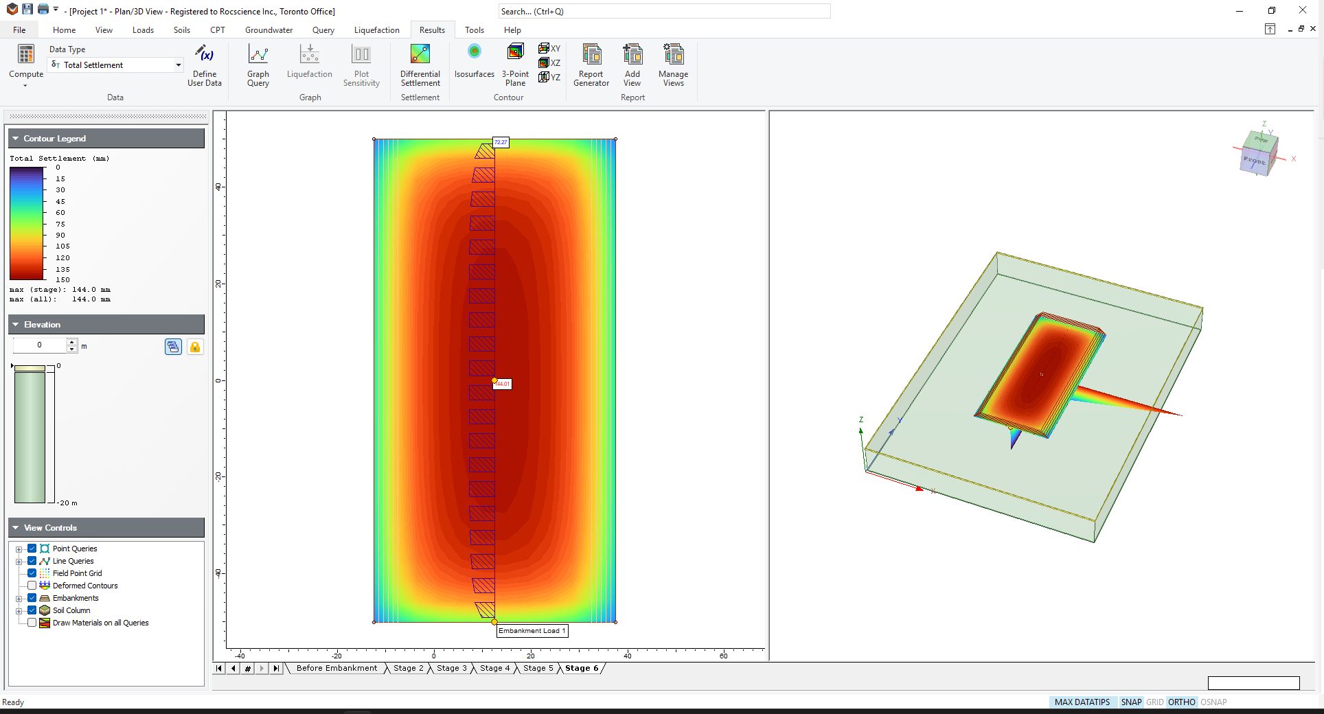
The maximum Total Settlement of 144.0mm can be seen in the Contour Legend and will act as a baseline to see how much improvement is obtained by performing Dynamic Compaction.
5.0 Ground Improvement – Dynamic Compaction
- Select Soils > Add Region

- Change the Method to Dynamic Compaction.
Set the following input values:
Drop Point Layout Pattern Square Spacing (m) 3 Drop Height (m) 30.2 Tamper Properties Shape of Base Circular Diameter (m) 1.5 Weight (t) 18.2 Dynamic Compaction Settings Calculation Method Using SPT Number of Passes 2 Number of Drops per Pass 6 nc 0.35 E/N 2 Stage In Before Embankment Ironing Pass Drop Pattern Square Drop Spacing (m) 3 Drop Height (m) 7.2 Number of Drops 3 Tamper Weight (t) 18.2 Calculate PPV Distance to Nearest Affected Structure (m) 20 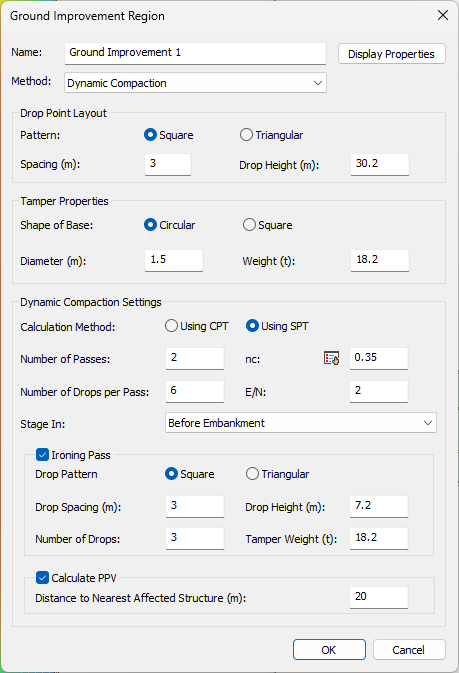
- Click OK
- You will be prompted to draw the Ground Improvement region in the 2D Plan View.
- Right-click on the model in the left-hand panel and make sure Snap is selected.
- Hover the mouse over each corner of the embankment and click to add a vertex to the Ground Improvement Region. Repeat until the embankment is fully enclosed by the region.
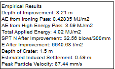
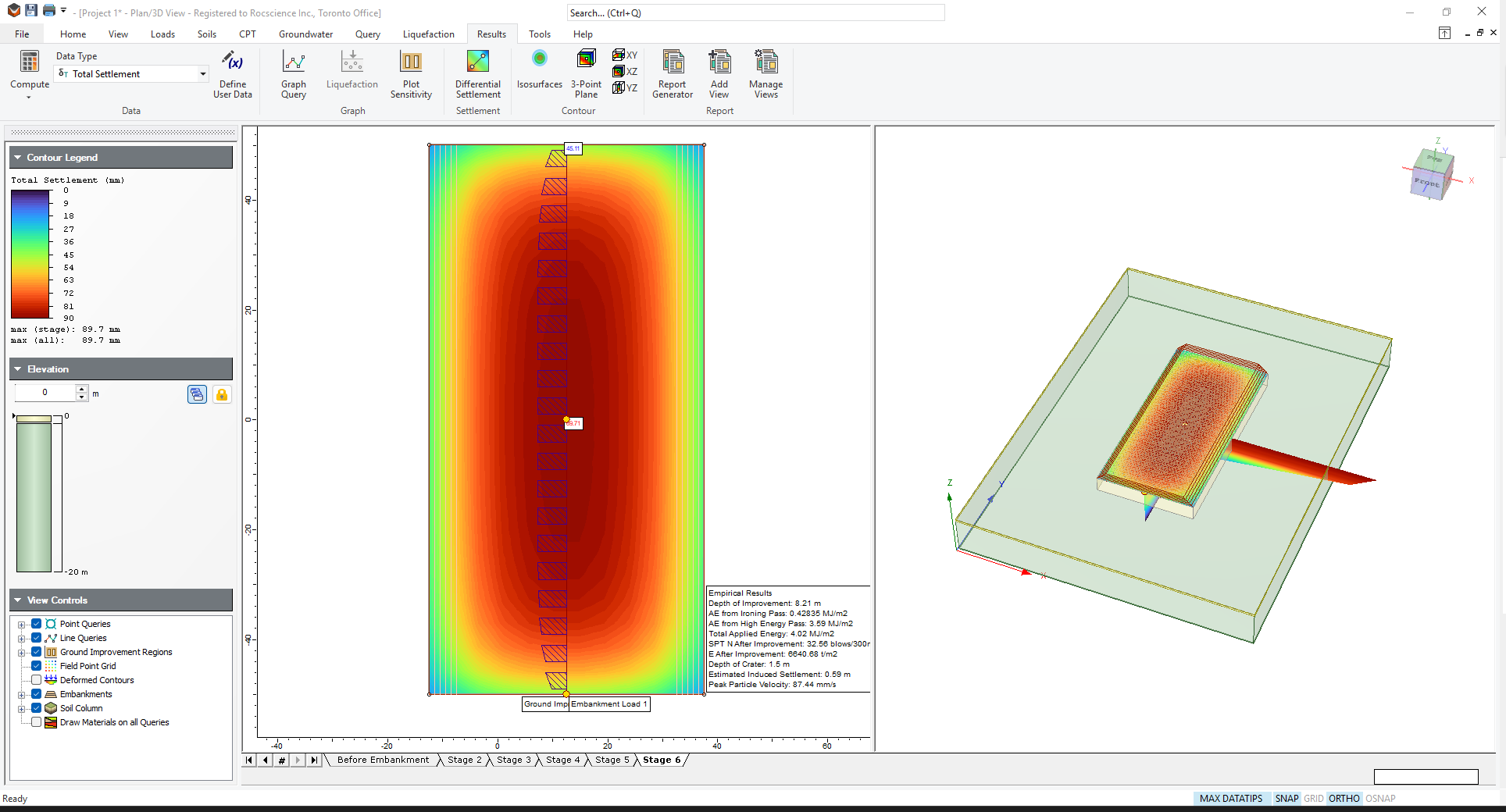
The empirical results of Dynamic Compaction are shown next to the region in the 2D view:
- Depth of Improvement
- Applied Energy from Ironing Pass
- Applied Energy from High Energy Pass
- Total Applied Energy
- CPT qc or SPT N After Improvement
- Elastic Modulus After Improvement
- Depth of Crater
- Estimated Induced Settlement
- Peak Particle Velocity
The Depth of Improvement is the Bottom Depth of the ground improvement region. For Dynamic Compaction, the top depth is equal to the depth of the ground surface. For more information, see the Settle3 Dynamic Compaction Verification Manual.
- Compute the settlement by selecting Results > Compute (Ctrl+T)
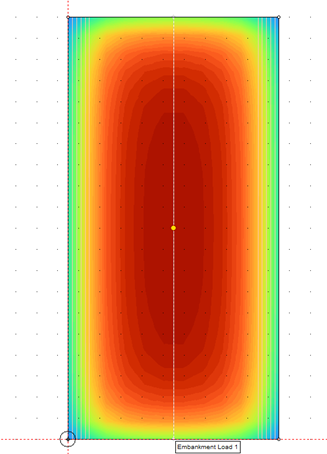
The updated contour plot is shown in the figure below and the new maximum Total Settlement is 89.7mm. Recall the baseline total settlement of 144.0mm.
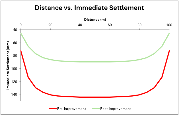
Additionally, the results of the query point at the center of the embankment and query line along the length can be plotted and compared against each other in Excel. The results of immediate settlement in Stage 6 for the query line along the length of the embankment compared pre- and post- improved are shown: