8 - Embankment Staging
1.0 Introduction
This tutorial introduces embankment design with multiple staging. This tutorial covers embankment designer along with advanced staging, increasing embankment width, adding embankment layers and assigning soil properties from published data.
Finished Product:
The finished product of this tutorial can be found in the Tutorial 08 Embankment Staging.s3z file. All tutorial files installed with Settle3 can be accessed by selecting File > Recent Folders > Tutorials Folder from the Settle3 main menu.
2.0 Defining the Model
2.1 Project Settings
- Select Home > Project Settings

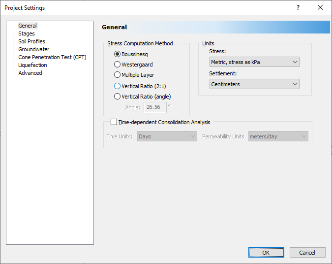
- Set the Stress units = Metric, stress as kPa and the Settlement units = Centimeters as shown.
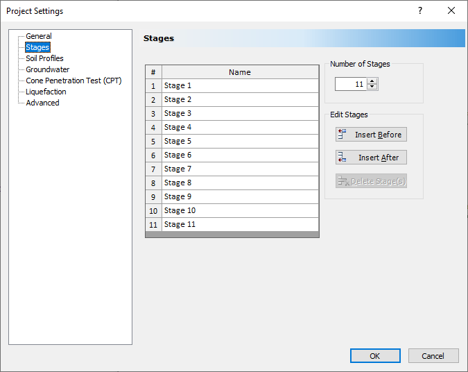
- Click on the Stages tab. Change the Number of Stages to 11.
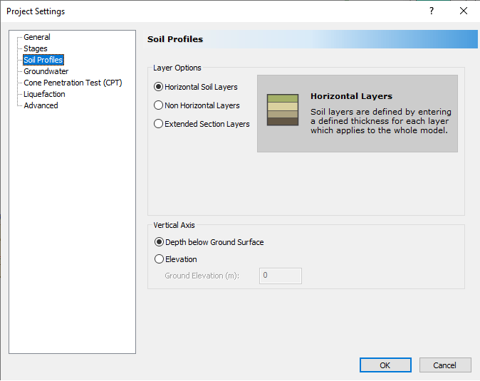
- Select Soil Profiles tab. Select the 'Depth below Ground Surface' option.
- Click OK to close the dialog.
3.0 Soil Properties
For this tutorial, we will assume a 2 m layer of sand on top of 10 m of clay.
- Select Soils > Define Soil Properties

- Change the name of Material 1 to Sand.
-
To choose a Unit Weight, click on the ‘Choose material property’
 icon to the right of the box where the unit weight is entered. You will see a dialog that specifies some Unit Weights from literature.
- Under Filter List, choose ‘Sand’ to show only the unit weights for sand. Select ‘Poorly-graded sands’ as shown.
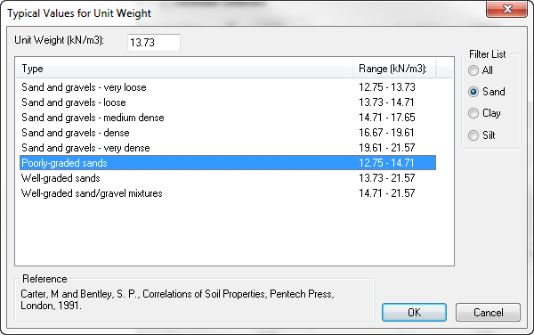
- You can see at the top of the dialog that the unit weight is set to the midpoint of the given range for poorly-graded sands (13.73 kN/m3). This is fine. Click OK.
- For Primary Consolidation, set the Material Type to Linear.If you click the icon to choose values for mv and filter the materials to show only sand, then you will see that there are no suggested values for sand.
- Use the default value in the Soil Properties dialog.
- Click on the tab for Soil Property 2. Change the name to Clay. For Unit Weight, click the icon to show typical values and filter to show only the Clay values. Choose ‘Clays – typical, normally consolidated’ as shown:

- Click OK
- For Primary Consolidation, click the icon to choose a value for Cc. Filter the values for Clay and choose ‘Normally consolidated, medium sensitive clays’.
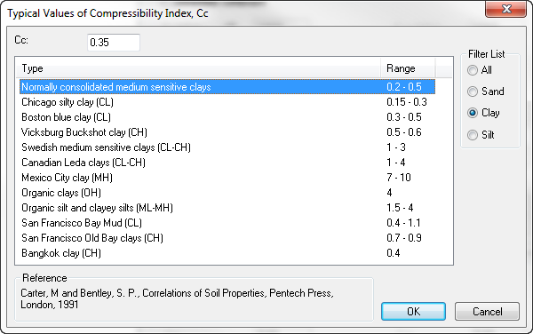
- Click OK. There is no data available for Cr so leave the default value of 0.1.
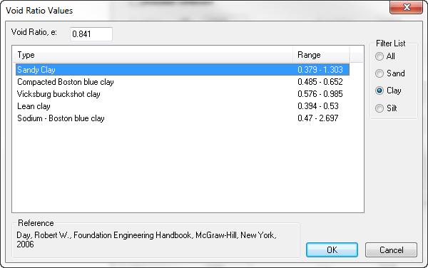
- Choose a value for the void ratio by clicking on the icon next to e0. Filter the list to show only clays, select Sandy Clay and click OK.
Your Soil Properties dialog should now look like this:
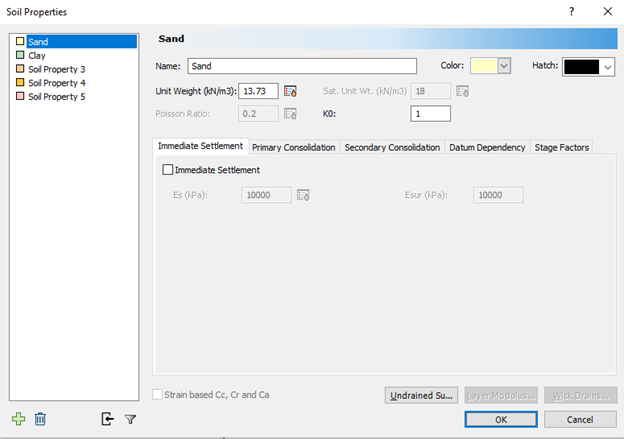
- Click OK to close the Soil Properties dialog.
4.0 Soil Layers
After defining the material properties, we create the soil strata, using the Soil Layers dialog.
- Select Soils > Layers
 .
.
By default, the dialog has the first layer defined with the first material defined in Soil Properties selected. - Change the thickness of the first soil layer to 2.
- Click the button for Insert Layer Below.
- Set the Thickness of this layer to 10 as shown.
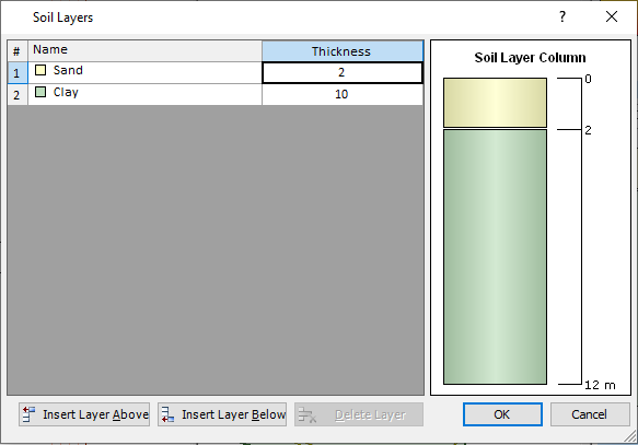
- Click OK to close the dialog.
5.0 Embankment Load
Now that we have defined the soil strata, it is time to build the embankment. We will simulate the construction history of the embankment by first building it upwards, then extending it horizontally, and then gradually removing it.
5.1 Initial Embankment Construction
- Select Loads > Loads by Layers
 to open the Embankment Designer dialog.
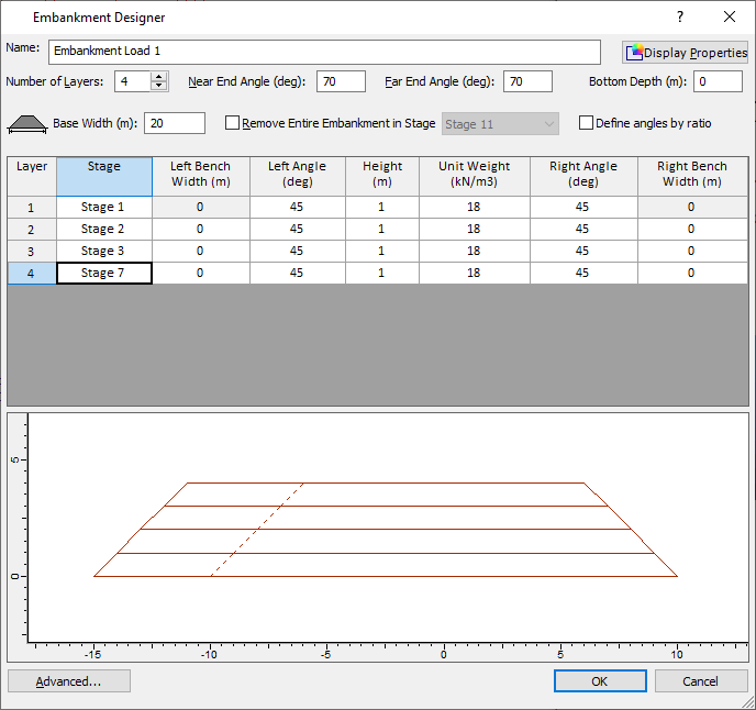
You will see the Embankment Designer dialog. - Change the Number of Layers to 3.
- Set the Near End Angle and Far End Angle to 70 degrees.
- We want to add the three layers in three different stages, so change the Stage for Layer 2 to Stage 2 and the Stage for Layer 3 to Stage 3.
The dialog should look like this: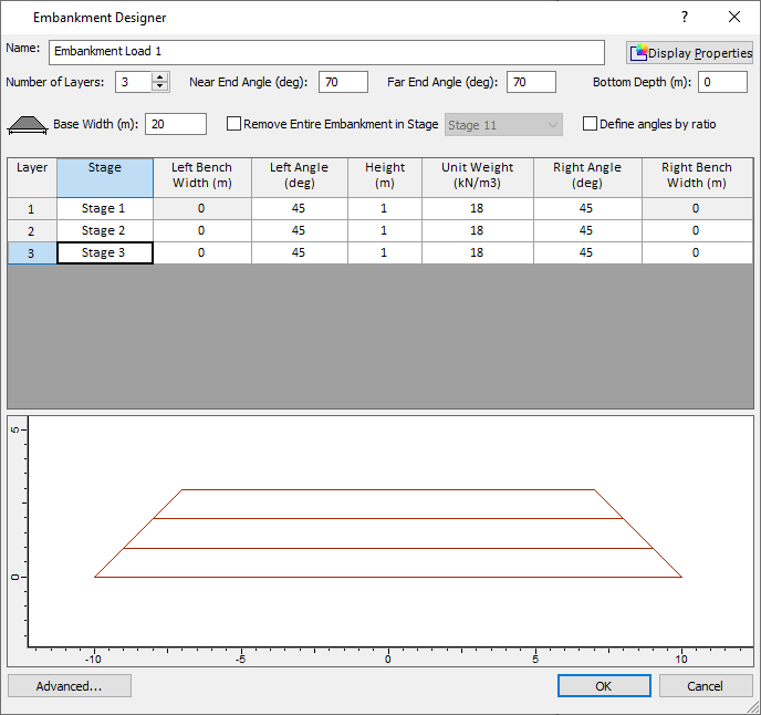
- Leave all other parameters as default values and click OK to close the dialog.
- You will now be prompted to enter the near point for the embankment centerline. Enter {0,-50} and press Enter.
- Now you are prompted to enter the far point. Enter {0,50} and press Enter.
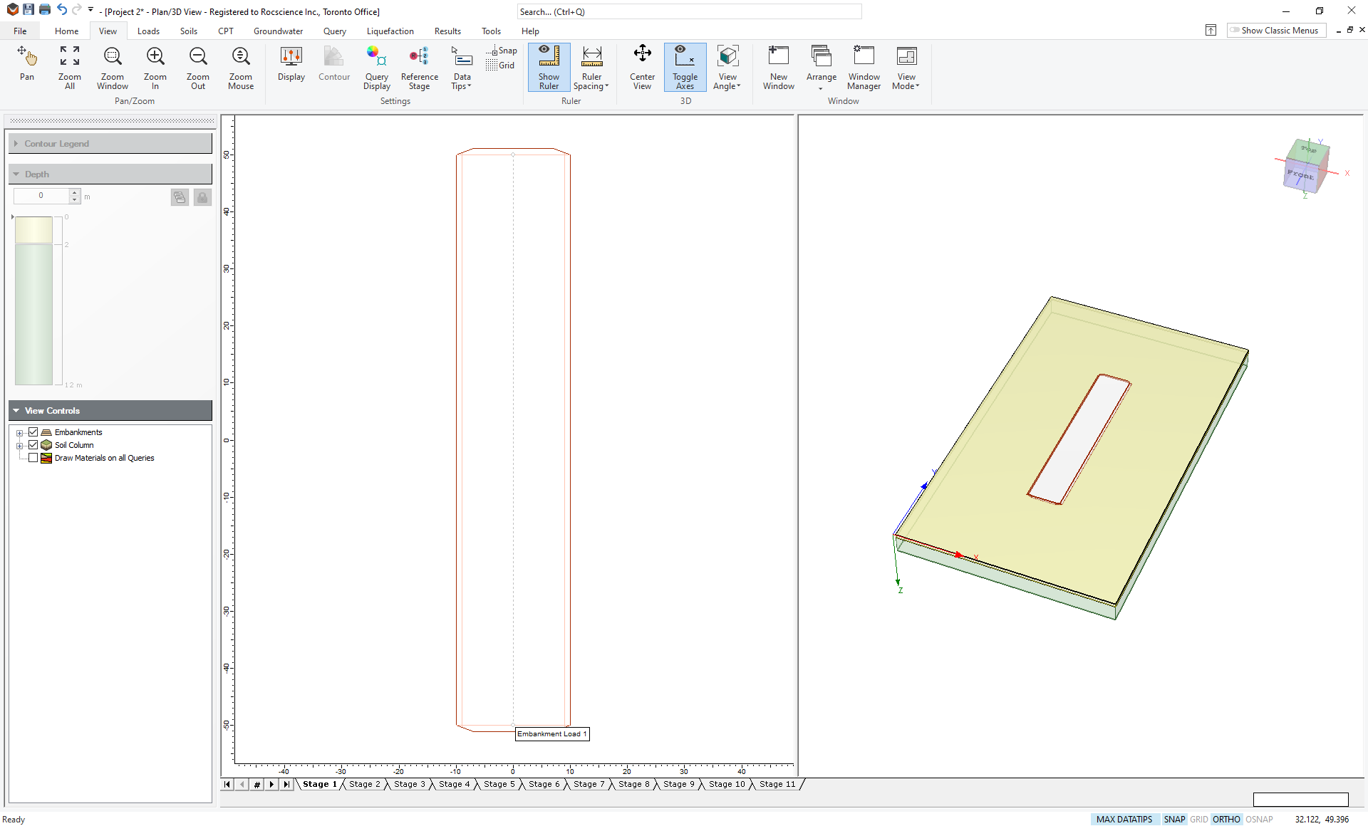
You should now see an embankment 100 m long as shown. You may need to zoom out in the Plan View. Click the Zoom All button (or press the F2 function key) to see the entire embankment.
To see the settlements caused by the embankment, we can add a query line.
- Select Query > Add Line from the menu. Leave the default query line properties as shown:
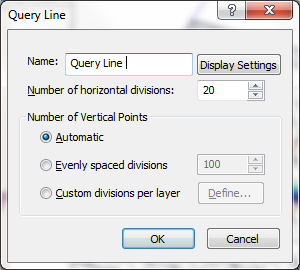
- Click OK and you will now have to enter the start and finish points for the query line. Enter {-20,0} and press Enter.
- Now enter {20,0} and press Enter.
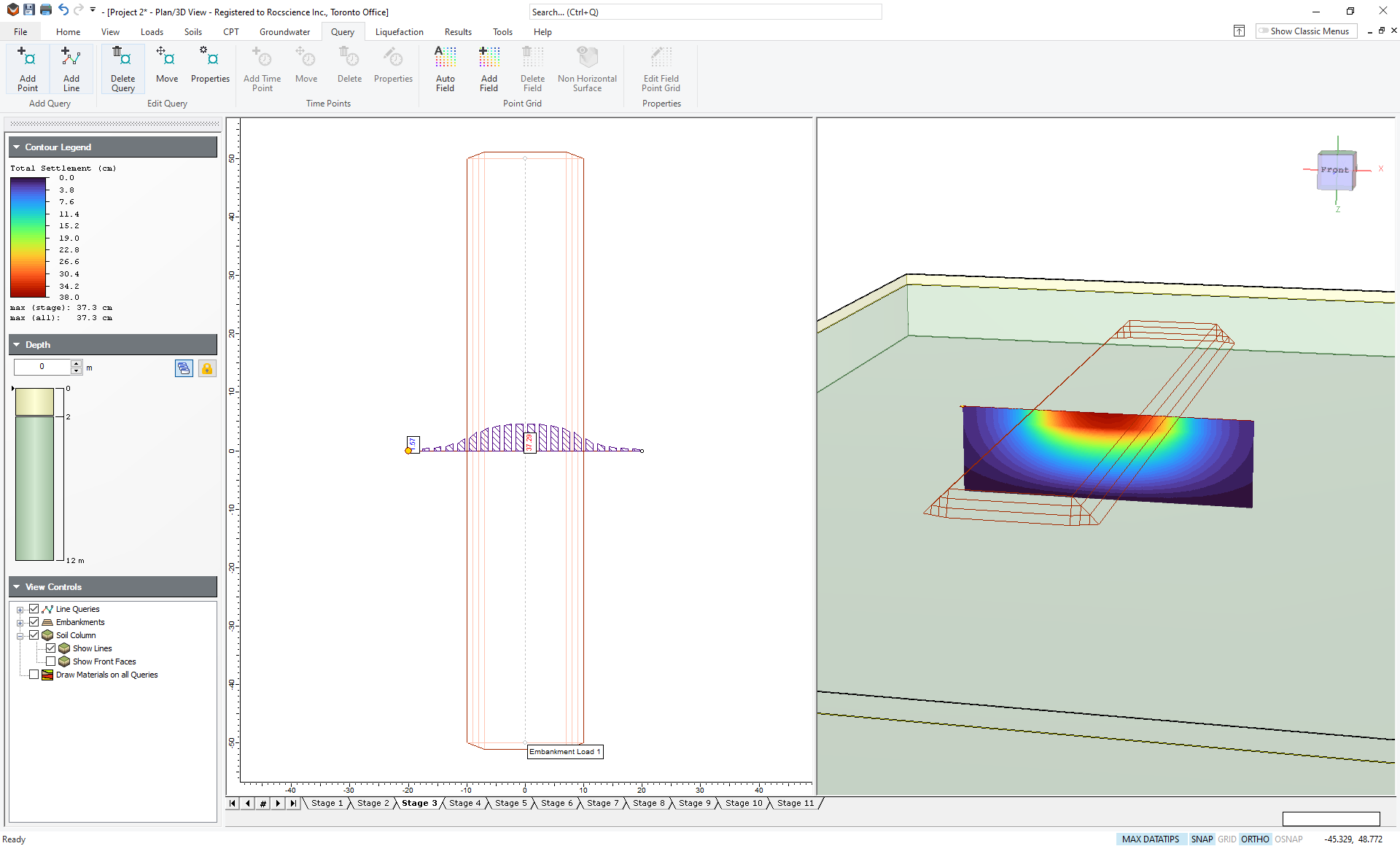
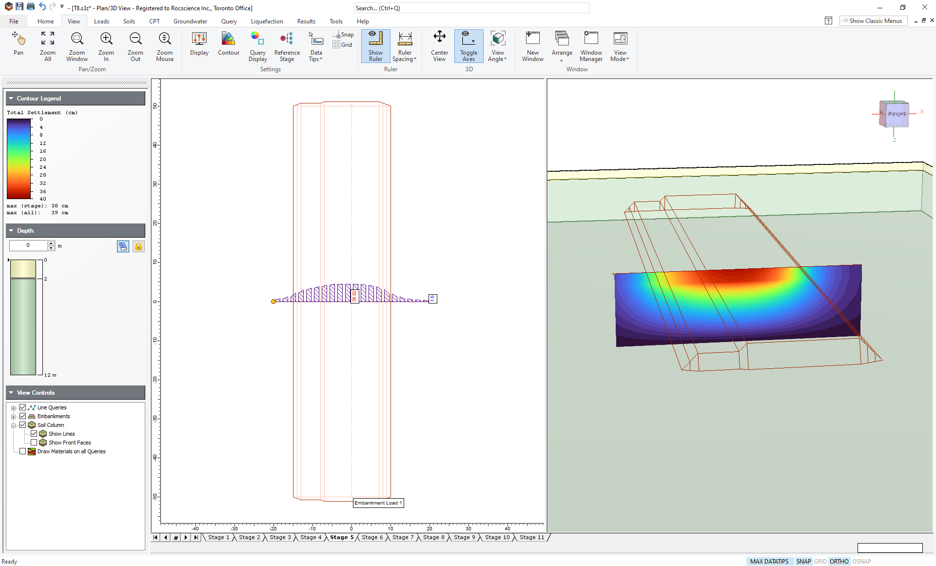
You will see the compute progress indicator. After a few seconds, you should see the query line with settlement results contoured in the 3D view. Uncheck Soil Columns > Show Front Faces in the View Controls to better see the results. Rotate the 3D view (by holding down the left mouse button while moving the mouse) and zoom in (by spinning the middle mouse wheel) and you should see the settlement profile as shown for Stage 1.
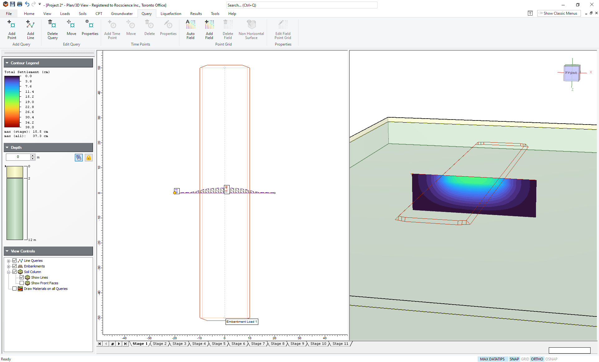
Click on the tab for Stage 2 and you will see the second layer of the embankment has been added and the settlement has increased. Stage 3 shows further construction and further settlement. The Plan View gives the minimum and maximum settlement along the query line (if you don’t see it, right-click on the query line, choose Query Display Options and check the box to display minimum and maximum values).
You may now want to save this model by going to File > Save As, before continuing with the tutorial.
6.0 Widening the embankment
We can now simulate the widening of the embankment by using the Advanced options in the Embankment Designer.
- Right-click on the embankment and select Embankment Properties
 . You will now see the Embankment Designer again.
 - Click on the Advanced button, and you will see the Advanced Embankment Staging dialog.
- Select the Advanced Staging checkbox.
- Click the Add button.
You will now see that you have the ability to add to the left and/or right of the embankment. You may want to move this dialog so that you can see the Embankment Designer at the same time.
We built the original embankment in Stages 1, 2 and 3. We will now widen it in Stages 4, 5 and 6. - Change the Stage to Stage 4.
- Change the Layer to 1.
- Under Add to left, enter 5 as shown.
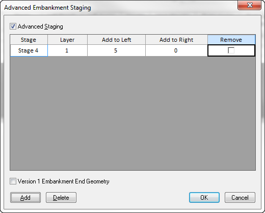
This will now extend the bottom layer of the embankment 5 m to the left in Stage 4. - Click the Add button two more times and fill in the dialog to extend the other two layers in Stages 5 and 6.
- For Stage 5 select Layer 2 and add 5 m to the left.
- For Stage 6 select Layer 3 and add 5 m to the left. The dialog should look like this.
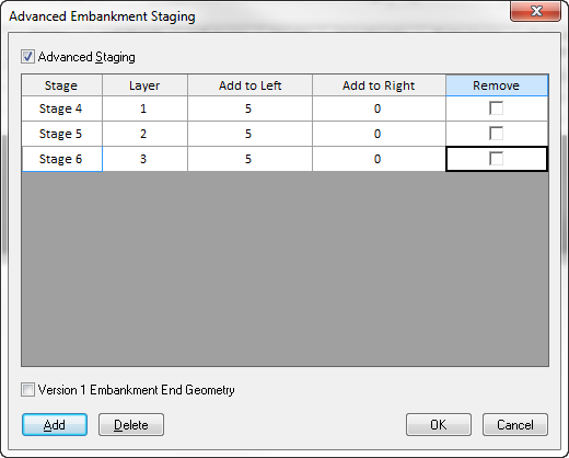
- Click OK to close the Advanced Embankment Staging dialog.
You will now be back in the Embankment Designer. You can see how the three layers have been extended to the left.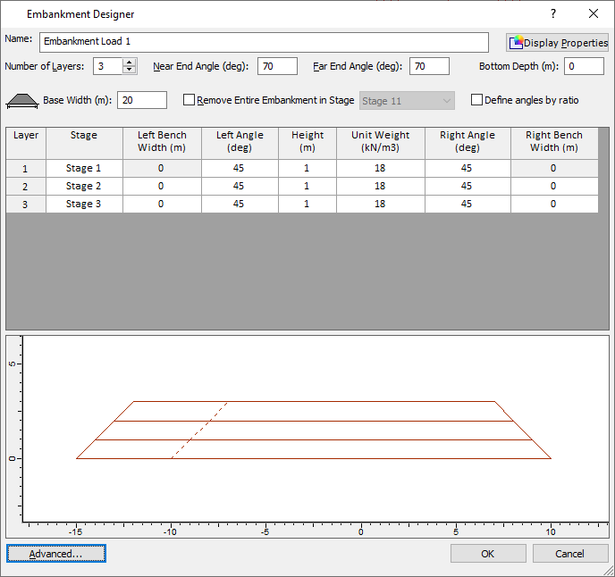
- Click OK.
Settle3 will take a few seconds to calculate the new settlement information. - Now click through the stages and observe the construction of the embankment and changes in calculated settlement through the stages. Stage 5 is shown below.
7.0 Embankment Top Layer
Now that the embankment has been extended, we want to add another layer.
- From the Loads tab, select Load by layers.
- Click on the embankment and press Enter. You will see the Embankment Designer once again
- Change the Number of Layers to 4.
- For the fourth layer, change the Stage to Stage 7 (recall that we extended the base in stages 4, 5 and 6). You can see that the top layer automatically extends over the original embankment width plus the extension.
- Click OK to close the dialog.
- After a few seconds, click on the tab for Stage 7.
You should see a maximum settlement of 47.7 cm.
8.0 Embankment Removal
We can now remove the embankment layer by layer and observe the effect on settlement.
- Right-click on the embankment and select Embankment Properties.
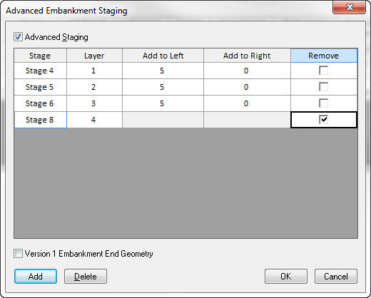
The main Embankment Designer allows you to remove the entire embankment at some stage. However, since we want to dismantle the embankment layer by layer, we need to click the Advanced button. - In the Advanced Embankment Staging dialog, click the Add button.
- Recall that we added the top layer in Stage 7, so we will remove it in Stage 8. Change the Stage to Stage 8.
- Leave the Layer as Layer 4.
- Check the box for Remove. The dialog will now look like this:
- Click the Add button three more times and remove layers 3, 2 and 1 in stages 9, 10 and 11 respectively.
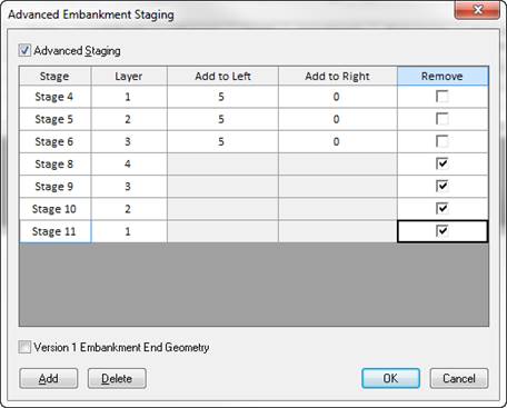
- Click OK to return to the Embankment Designer.
- Click OK to close the Embankment Designer.
After a few seconds, click through stages 8-11 and observe the change in embankment geometry and settlement as layers are removed. The plot below shows the results in Stage 11, when the entire embankment has been removed.
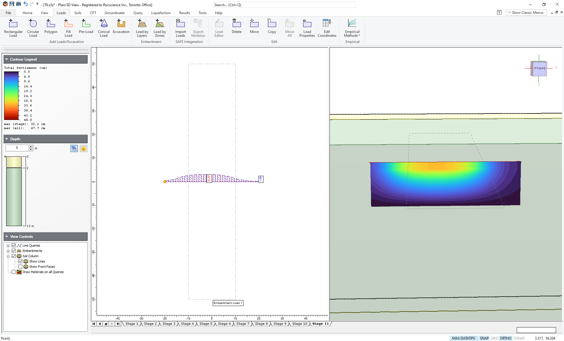
You can see that the calculated settlement for this stage is 32.1 cm. The settlement is greater than zero, even though there is no load. This is because the clay layer is hysteretic, i.e. it is stiffer during unloading, than during loading (Cr < Cc), therefore there is some permanent settlement even after the load is removed.
This concludes the tutorial.