Underground Tunnels
1.0 Introduction
This tutorial will demonstrate some of the consolidation features of RS3. Here we create multiple layers of embankment on multiple layers of soil using boreholes. All tutorial files installed with RS3 can be accessed by selecting File > Recent > Tutorials folder from the RS3 main menu. The finished product of this tutorial can be found in the Underground Tunnels.rs3v3 file. The starting file can be found in Underground Tunnels - starting file.rs3v3 file.
2.0 Starting the Model
- Select File > Recent > Tutorials in the menu.
- Open the starting file Underground Tunnels - starting file.rs3v3.
All the project settings and material definitions are predefined in the starting file. Read through these two sections to make sure the inputs in the model are consistent with this tutorial.
- Select: Analysis > Project Settings

- The Project Settings dialog is used to configure the main analysis parameters for your RS3 model. In Units tab, set Units = Metric, stress as MPa.
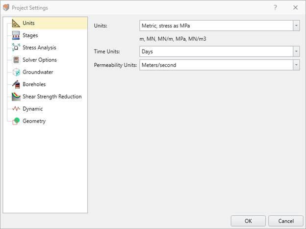
- Next, select the Groundwater tab.
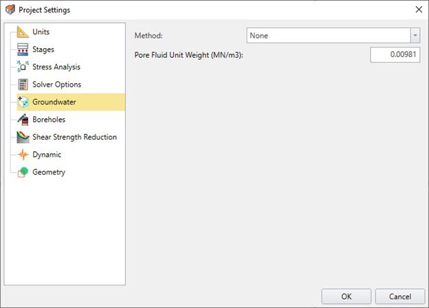
- Check Method = None and click OK to close the dialog.
3.0 Import Examine3D File
Importing the Tunnel Geometry
- Select: File > Import > Import Examine3D file.
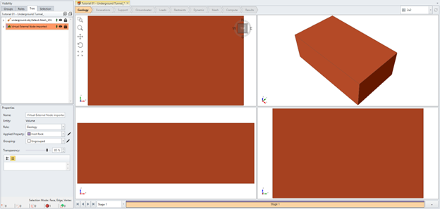
- Select UndergroundTunnels.ex3 (from the tutorial folder File > Recent > Tutorials > Underground Tunnels - starting file), ensure that when selected in the visibility pane, that in the properties pane for the underground tunnels, the Role = Excavation, and Applied Property = No Material.
4.0 Defining External Box
- Ensure the Geology workflow tab
 is selected from the top of the screen.
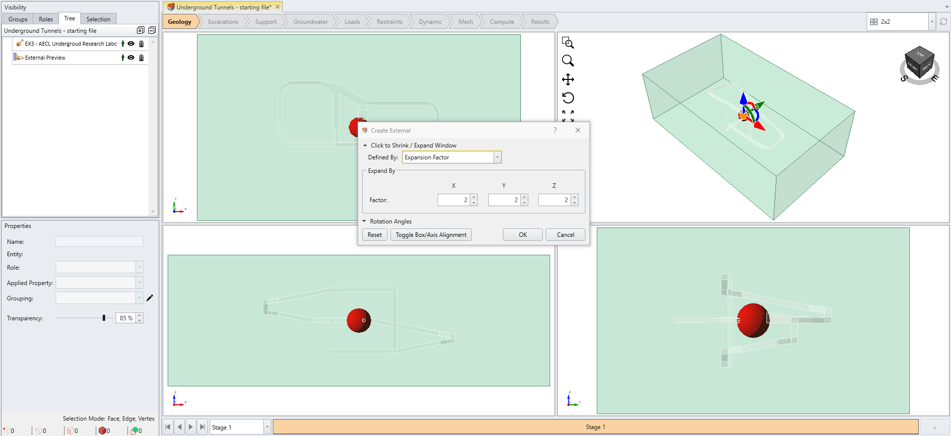
 - Select: Geometry > Create External Box.
- A Create External dialog will open. Enter Expand by = 2 for all of X, Y, and Z, press [Update Preview] to update the selection. Then click OK.
5.0 Defining Material Properties
Under the same tab (Geology or Excavations) you can assign the materials properties. When Examine3D file is imported, the material properties should be imported together. However, those parameters that are not specifically defined in Examine3D are set as default.
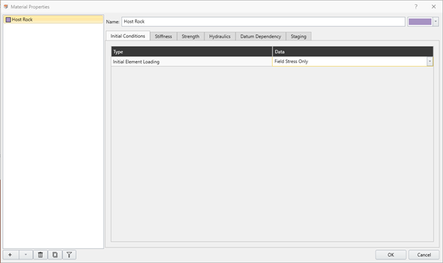
- Select: Materials > Define Materials.
- The import should have brought the material properties from the Examine3D model. Select [Examine3D – AECL Underground Research Laboratory Material]
- Under Initial Conditions, switch Initial Element Loading from Field Stress & Body Force (Default) to Field Stress Only. This is to conduct the stress analysis just based on the stiffness of the rock and the induced stress.
- Select External_1 entity under Visibility Tree
- Under Properties pane, assign [Examine3D – AECL Underground Research Laboratory Material] to its applied property
6.0 Divide All Geometry
Now we can cut into the external box with the tunnels:
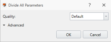
- Select: Geometry > 3D Boolean > Divide All Geometry

- Click OK to close the dialog.
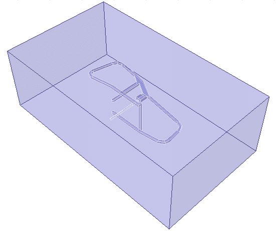
Your model should now appear as below:
7.0 Adding Stress Loading
- Next, we go to the Loads workflow tab
 . This tab allows you to edit the loading conditions.
 - Select: Loading > Field Stress.
- Check the following field stress, the imported geometry should have this condition as shown below:
- Field Stress Type = Constant
- Sigma 1 = 60 MPa
- Sigma 2 = 50 MPa
- Sigma 3 = 15 MPa
- Defined by = Trend & Plunge
- Sigma 1 (Trend, Plunge) = (117, 0)
- Sigma 3 (Trend, Plunge) = (0, 90)
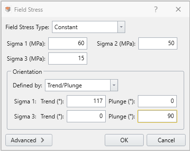
Click OK
8.0 Setting Boundary Conditions
Adding Model Restraints
- Navigate to the Restraints workflow tab
 to assign restraints to the external boundary of the model.
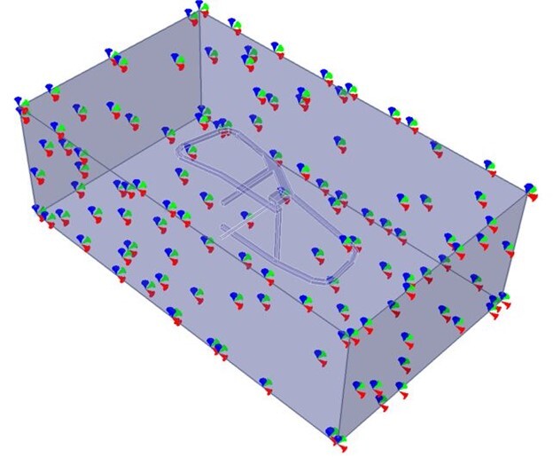
RS3 has a built-in “Auto Restrain” tool for use on underground models.
- Select: Restraints > Auto Restrain (Underground). You should see the restraints on the model as shown below:
9.0 Meshing
Configuring and Calculating Mesh
- Next, we move to the Mesh workflow tab

- Select: Mesh > Mesh Settings

- Enter Element Type = 4-Noded Tetrahedra, and Mesh Gradation = Graded.
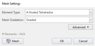
- Click Mesh to mesh the mode
The mesh is now generated, your model should look like the one below.
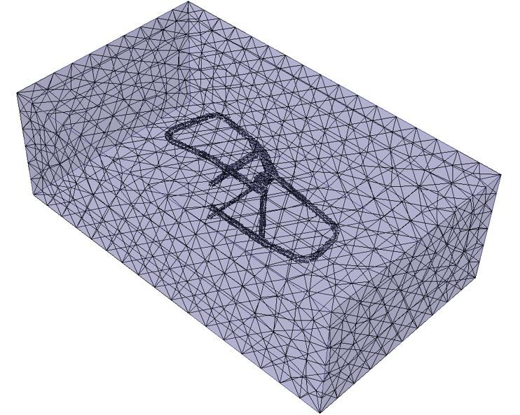
This completes the construction of the model
10.0 Computing Results
- Next, we move to Compute workflow tab
 . From this tab, we can compute the results of our model.
 - From this tab, we can compute the results of our model. Before commencing the stress analysis computation, it is recommended to save the final model as a separate file so that you can access the original file anytime: File > Save As.
- Select: Compute > Compute

11.0 Interpreting Results
11.1 Displaying the Results
- Next, we move to Results workflow tab
 . From this tab, we can analyze the results of our model. First, refresh the results:
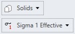
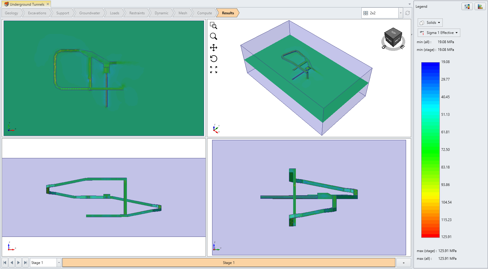
 - On the top right corner of the Results tab, you should see two drop-down menus:
- Select: Interpret > Show Excavation Contour

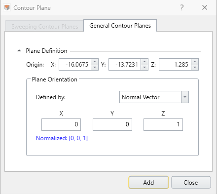
We also want to define a plane that goes through the slanted cross tunnel. First, we must define a plane,
- Select: Interpret > Show Data on Plane > XY Plane

- In the Create Plane dialog, check if the default setting is in center coordinates as shown below. If not, enter: Center of (x, y, z) = (-16.0675, -13.7231, 1.285), Normal Vector of (x, y, z) = (0, 0, 1), then press OK.
In the top right corner of the Results tab, ensure Element = Solids, and change Data Type = Solid Displacement > Total Displacement:
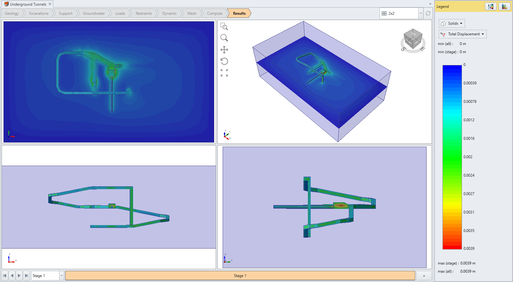
This concludes the Underground Tunnel tutorial.