11 - Earthen Berms
This tutorial introduces the addition of Berms to a RocFall2 model and how to interpret berm results.
Topics Covered in this Tutorial:
- Adding berms
- Graphing berm results
Finished Product
The finished product of this tutorial can be found in the Tutorial 11 - Earthen Berms data file. All tutorial files installed with RocFall2 can be accessed by selecting File > Recent Folders > Tutorials Folder from the RocFall2 main menu.
1.0 Introduction
A berm in RocFall2 is a polyline consisting of at least two segments with both the first and last points on the slope that can be placed almost anywhere along the slope to alter the paths of the rocks as they travel down the slope. To add a berm, you need to define and/or assign both:
- Berm geometry
- Berm material
RocFall2 offers three different options for berm geometry: triangular berms, trapezoidal (embankment) berms, and custom berm shapes. Any number of berms can be added to the slope. Berms, however, cannot cross other berms and cannot cross slope segments. If the last point is inside the slope, the last segment will be truncated promptly at where it meets the slope. Also, a berm cannot have self-intersecting segments. Moreover, the berm must be placed where a valid last point can be generated; an intersection with the slope must be reachable by extending either the last segment or vertically down. For example, it cannot end beyond the slope or have an ending angle that’s less steep than the general slope. A warning message will pop up if an invalid location is picked.
2.0 Model
Let's start by opening the file for the tutorial:
- Select: File > Recent Folders > Tutorials Folder and open the Tutorial 11 initial file.
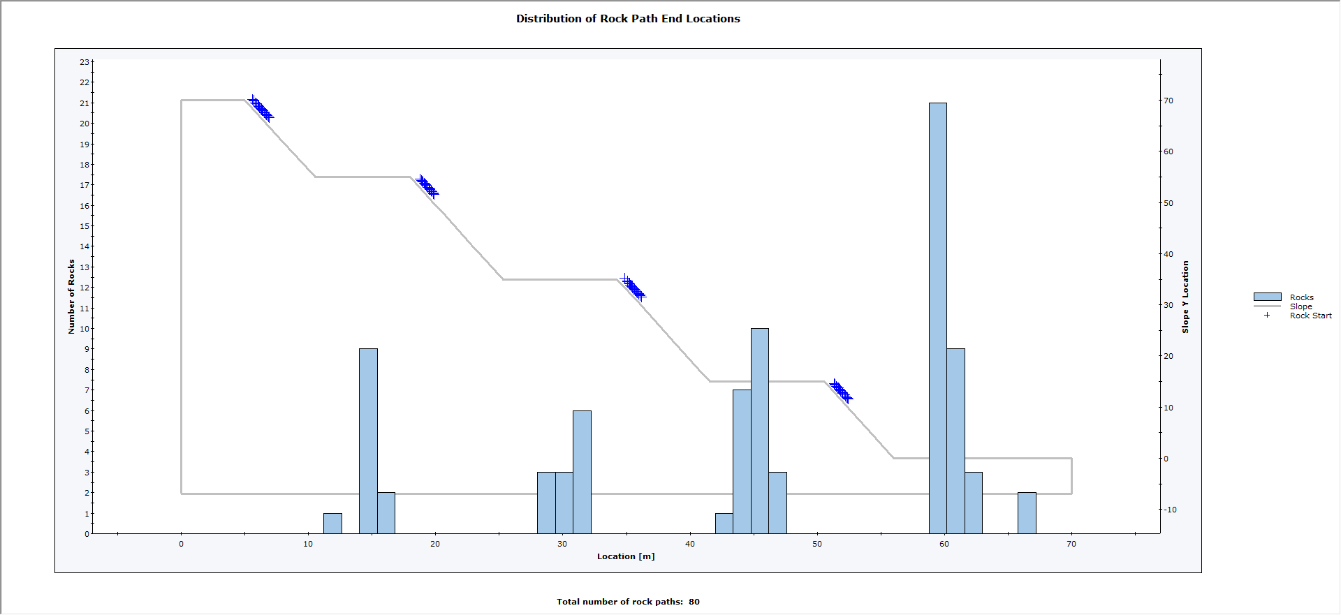
You should see the following model.
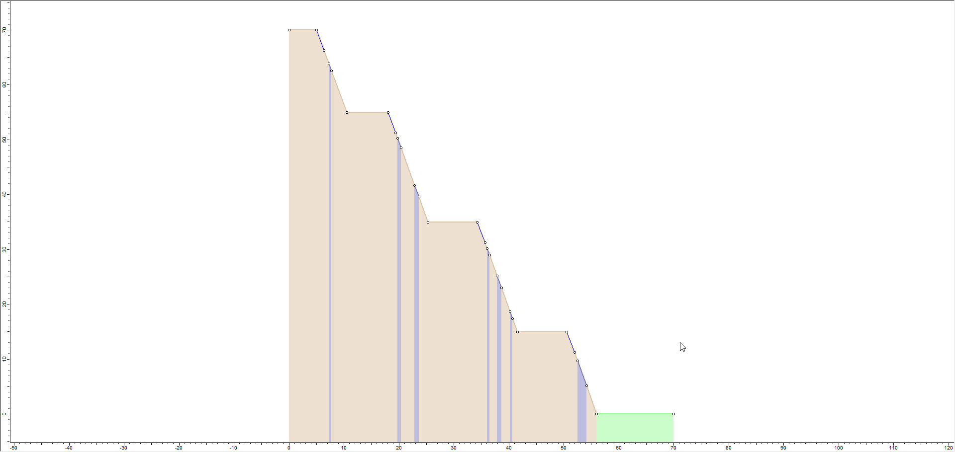
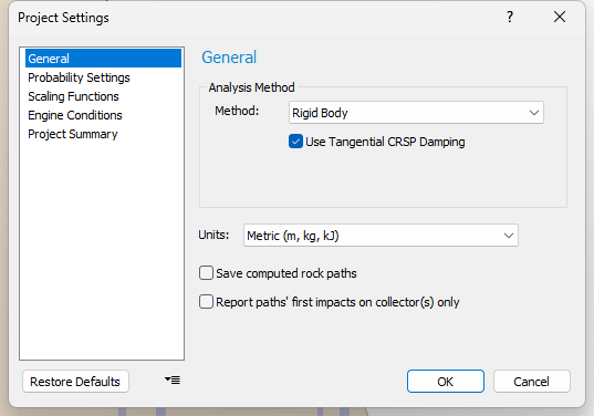
This file has all geometry and properties pre-defined, except for the berm. File properties include:
- Analysis Method = Rigid Body
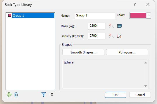
- A single Rock Type (Group 1) and Shape (Sphere)
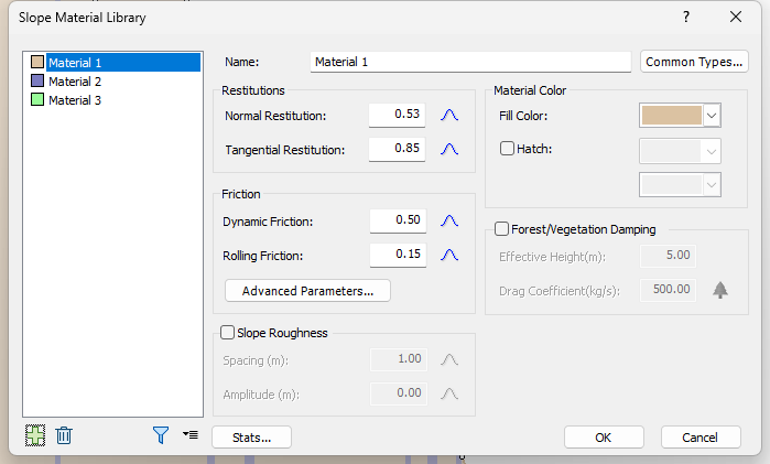
- Three Slope Materials with Statistical Distributions of Normal and Tangential Restitution coefficients, Dynamic and Rolling Friction coefficients.
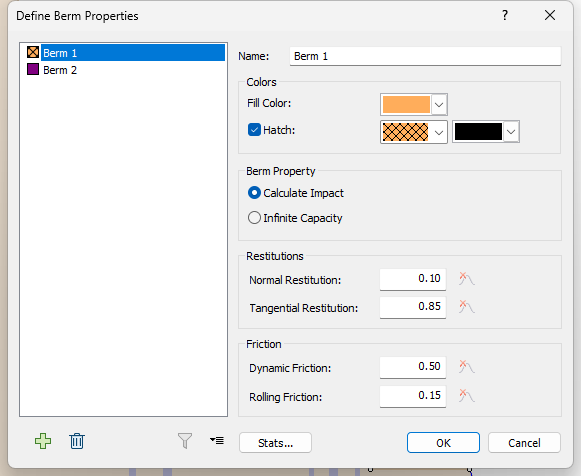
- Two Berm Materials with Calculate Impact and Infinite Capacity, respectively.
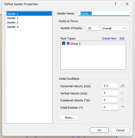
- Line seeders with Statistical Distribution of Initial Horizontal Velocity and Number of Rocks = 20.
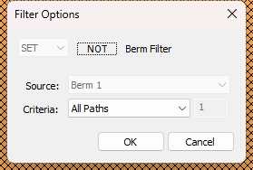
3.0 Results: No Berm
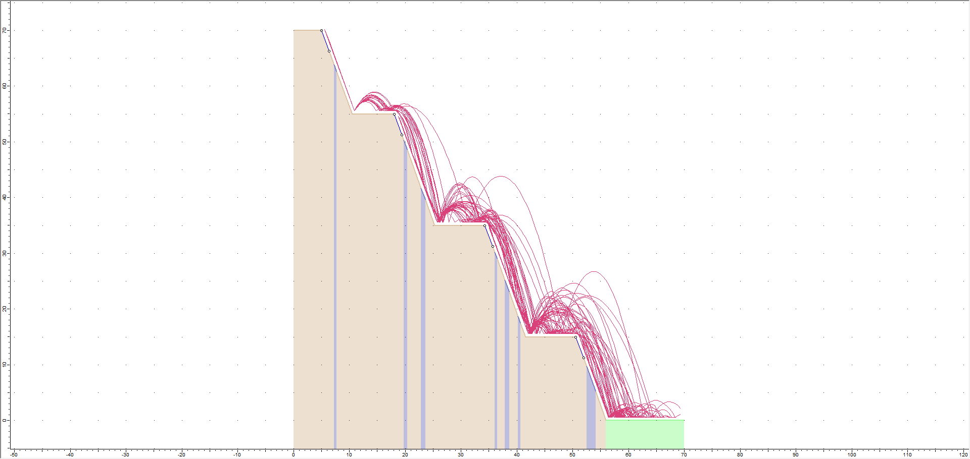
Let’s first look at the results with no berm.
- Select the Compute
 option from the toolbar or the Analysis menu.
You should see the following:
4.0 Adding Berms
Now we'll add berms to the model using the Add Berm option and Berm Designer dialog.
4.1 ADD THE FIRST BERM
- Select Design
 on the toolbar.
 - Select Add Berm
 on the toolbar or the Berms menu.
The Berm Designer dialog appears. - Keep Name = Berm 1, Berm Properties = Berm 1, and Berm Shape = Triangular.
- Set Height (m) = 1.5.
- Set Angle 1 and Angle 2 = 36.87.
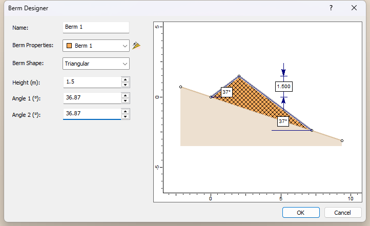
- Click OK.
The cursor should turn into cross hairs. - Right-click on the model and select Snap to Last Point in the popup menu.
- Click on the edge of the first bench on the slope to place the berm.
4.2 ADD THE SECOND BERM
- Select Add Berm on the toolbar or the Berms menu.
- Keep Name = Berm 2 and Berm Properties = Berm 1.
- Set Berm Shape = Custom.
- Keep Close Berm Polyline = Vertical.
- Enter the coordinates shown below.
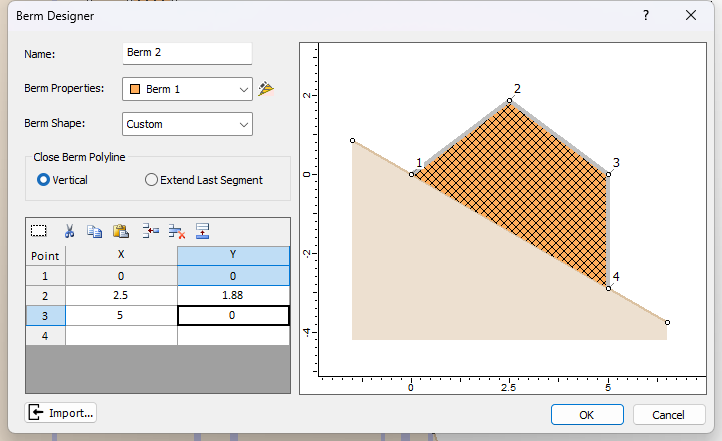
- Click OK.
- Click on the edge of the second bench on the slope to place the berm.
4.3 ADD THE THIRD AND FOURTH BERMS BY COPYING
Now we'll add the last two berms using the Copy Berm ![]() function.
function.
- Right-click on the second berm and select Copy Berm in the popup menu.
- Click on the edge of the third bench to paste the berm as a new berm.
- Right-click on the first berm and select Copy Berm in the popup menu.
- Enter the coordinates 63.5, 0 in the input box in the bottom-right of the application window and press ENTER to add the fourth berm.
4.4 ASSIGN BERM MATERIALS
By default, new berms are assigned the default Berm 1 material. Let's assign the Berm 2 material to the fourth berm.
- Select Berms > Assign Berm Materials
 .
.
An Assign dialog appears.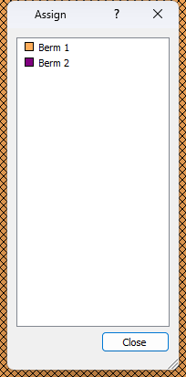
- Select Berm 2 in the list and then click on the fourth berm at the bottom of the slope.
You should see the berm colour change to the colour for Berm 2. - Close the Assign dialog.
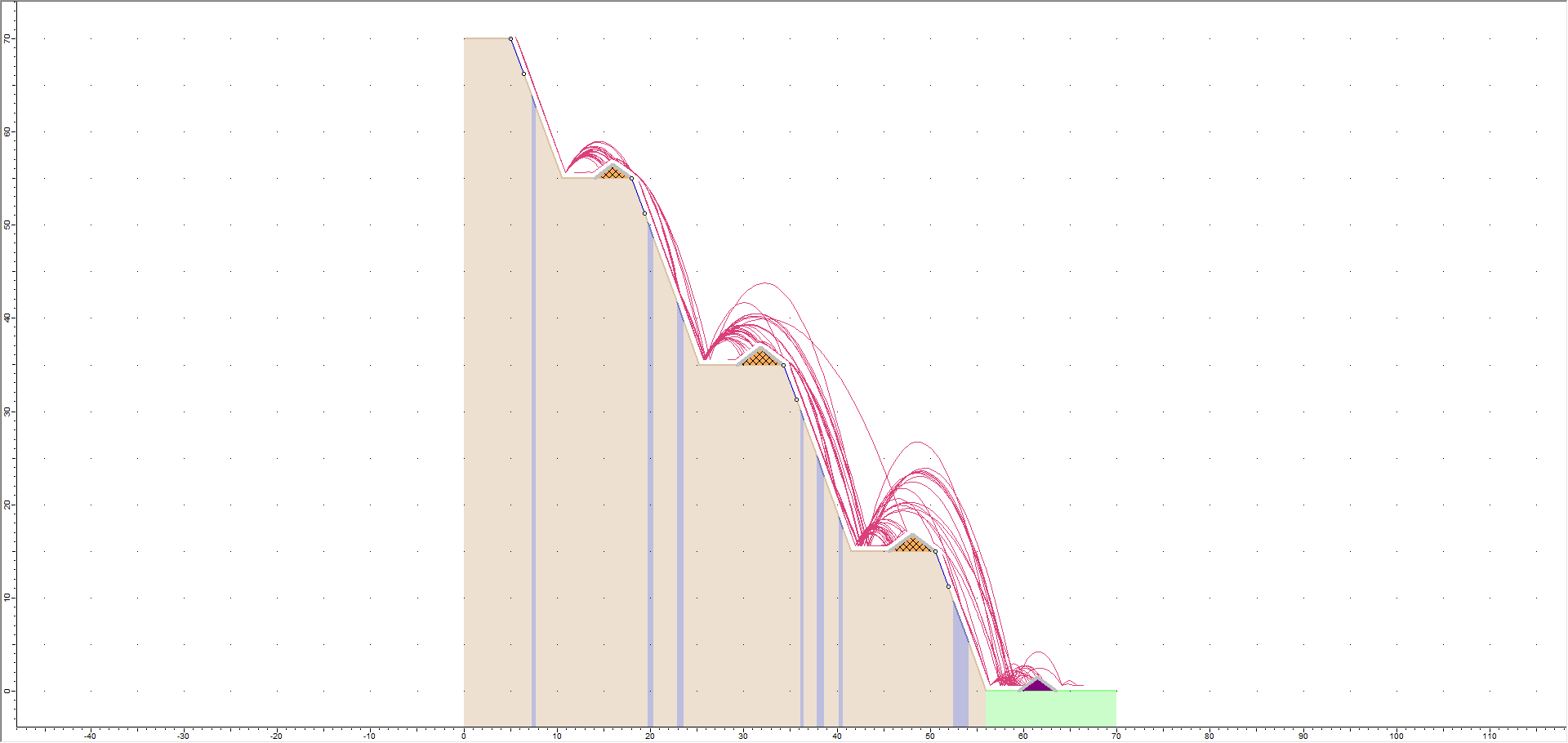
5.0 Results and Discussion: With Berms
Now let's look at the results with the berms added.
- Select the Compute option from the toolbar or the Analysis menu.
You should see the following:
5.1 ANIMATE RESULTS
Next, let's animate the rock paths.
- Right-click on any rock path and select Animate Path in the popup menu.
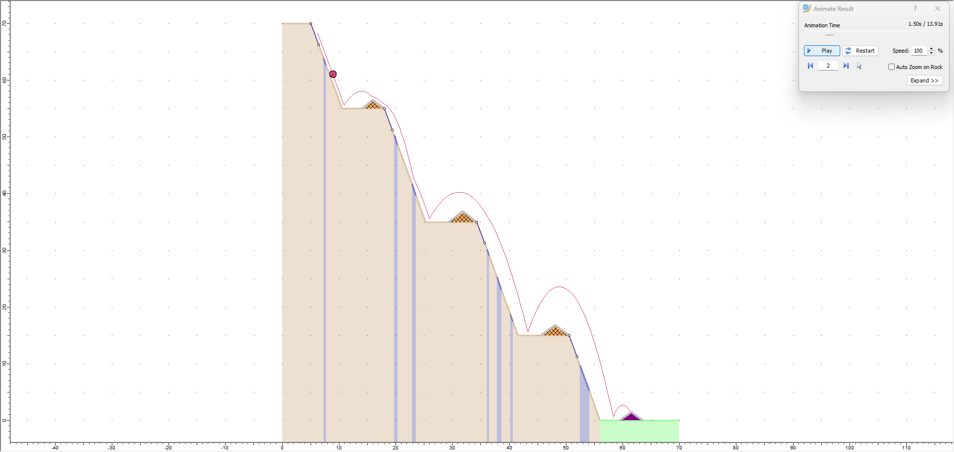
- In the Animate Result dialog, click the Back and Forward arrows to cycle through each rock in the model (Rock ID) and play its animation.
- Close the dialog.
NOTES:
- Notice that when a rigid body rock shape (in this case a sphere) hits a berm with infinite capacity (the last one at the bottom of the slope), it stops as the centroid of the shape intersects the berm. Rocks don’t bounce off berms with infinite capacity. The radius or size of the rock is not accounted for when a rock shape collides with this berm; only the centroid of the shape is used to determine the intersection, as you can see from the final position of the rock on the berm.
- By chance this rock (Rock ID 36) also hits another berm that calculates impacts (on the 2nd bench). Impacts were calculated the same way as with the slope.
5.2 ENDPOINT GRAPH
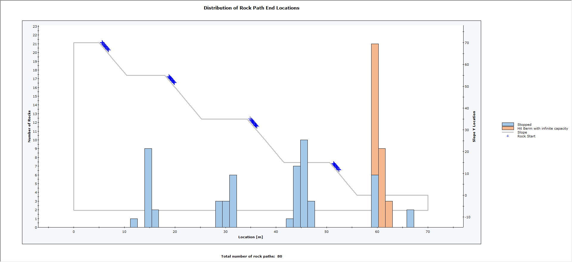
If you plot the Endpoint Locations ![]() graph and right‐click and select Toggle End Reasons, you will see that all rocks are stopped or slowed by the berms without running off the end of the slope.
graph and right‐click and select Toggle End Reasons, you will see that all rocks are stopped or slowed by the berms without running off the end of the slope.
5.3 FILTERING BERM RESULTS
For each berm, you can apply filters to generate detailed and focused results. For each berm, you can apply the following filters:
- All Paths
- Highest Total Energy
- Highest Translational Energy
- Highest Rotational Energy
- Highest Translational Velocity
- Highest Rotational Velocity
Aside from All Paths, you can enter the number of rocks to be included so that number of rocks that have the most selected criteria will be included.
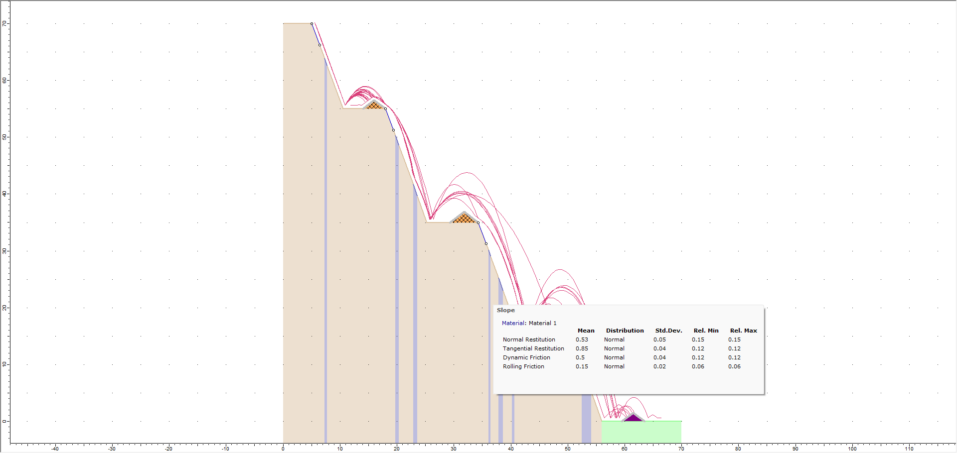
- Right-click on the berm on the first bench and select Filter by Impact in the popup menu.
The Filter Options dialog appears. - Make sure Criteria = All Paths.
- Select OK. Only the rock paths that hit the first berm remain.
- Plot the Endpoint Locations
 again as above.
You should see the following:
We can see that five rocks weren’t slowed by the first bench and traversed beyond the first bench. We can see that these five rocks impact higher up close to the tip of the berm. Instead of bouncing backward, they roll over and down the slope and are eventually stopped by the last berm.
5.4 GRAPHING BERM RESULTS
For each berm, the following graphs can be plotted for rocks that strike the berm:
- Total Kinetic Energy
- Translational Kinetic Energy
- Rotational Kinetic Energy
- Translational Velocity
- Rotational Velocity
- Vertical Impact Height
- Impact Angle
- Absorbed Energy (non-infinite berms only)
- Select Toggle Filter
 on the toolbar to clear the filter set above.
 - Right-click on the berm on the second bench and select Graph Berm Data
 in the popup menu.
The Graph Berms dialog appears. - Select Vertical Impact Height as the Data to Plot.
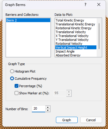
The Vertical Impact Height is measured from the impact points to the y location of the slope with the same x coordinate. - Click Graph.
- Repeat the steps above but select Histogram Plot as the Graph Type instead.
- Tile the views for comparison.
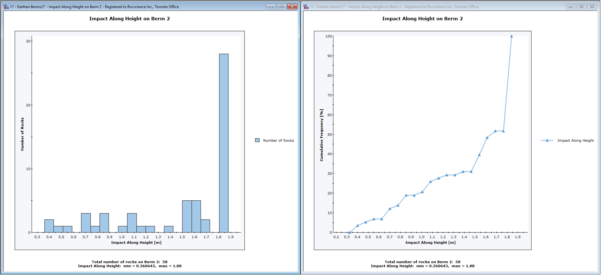
This concludes the tutorial.