4 - User Planes
1.0 Introduction
This tutorial covers the creation of user-defined planes via the Add User Plane option.
Topics Covered in this Tutorial:
- Add User Plane
- Major Planes Plot
Finished Product:
The finished product of this tutorial can be found in the Tutorial 04 User Planes.dips9 file, located in the Examples > Tutorials folder in your DIPS installation folder.
2.0 Model
If you have not already done so, run DIPS by double-clicking on the DIPS icon in your installation folder. Or from the Start menu, select Programs > Rocscience > DIPS > DIPS.
If the DIPS application window is not already maximized, maximize it now, so that the full screen is available for viewing the model.
DIPS comes with several example files installed with the program. These example files can be accessed by selecting File > Recent > Examples Folder from the File menu (or File > Open from the Home ribbon). This tutorial will use the Example.dips9 file to demonstrate the basic plotting features of DIPS.
- Select File > Recent > Examples Folder
 from the menu.
 - Open the Example.dips9 file. Since we will be using the Example.dips9 file in other tutorials, save this example file with a new file name without overwriting the original file.
- Select File > Save As
 from the menu.
 - Enter the file name Tutorial 04 User Planes and Save the file.
3.0 Pole Data Grid
If the Pole Data Grid is not already the active view:
- Select the Pole Data Grid
 view tab.
You should see the Pole Data Grid view shown in the following figure.
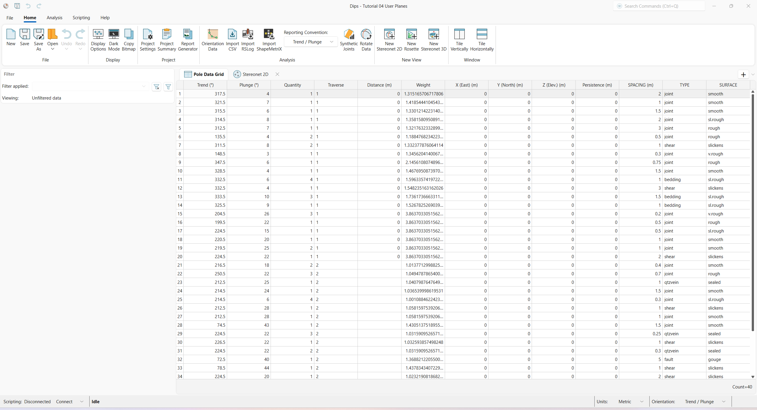
The Pole Data Grid shows all processed orientation data entered in the Orientation Data dialog. Note that there are 40 rows of data (i.e., Count=40).
4.0 Stereonet 2D
Now look at the Stereonet 2D view:
- Select the Stereonet 2D
 view tab.
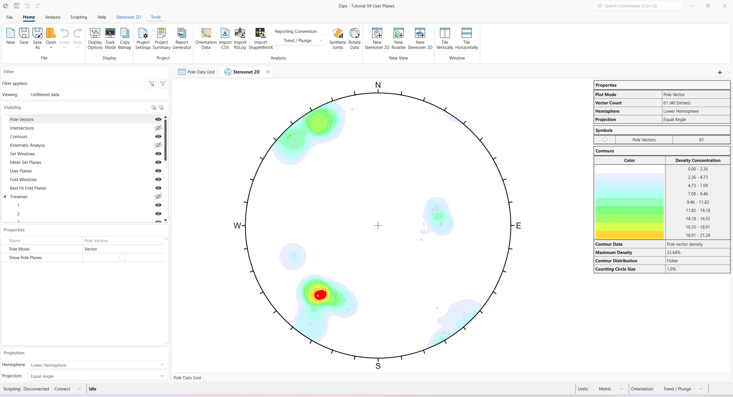
You should see the Stereonet 2D view shown in the following figure.
5.0 Add User Plane
The Add User Plane option allows you to graphically add a user-defined pole/plane to a stereonet plot.
- Select Stereonet 2D > User Planes > Add User Plane
 from the ribbon.
 - Move the cursor over the stereonet. When the cursor is INSIDE the stereonet, an arc or “great circle” representing the plane corresponding to the cursor location (pole) will appear. Move the cursor around the stereonet and observe the position of the corresponding plane. The cursor coordinates are visible in the Status Bar at the lower-right corner of the application. The coordinate display convention can be changed in the Orientation reporting convention button drop down in the Status Bar.
- When the plane/pole is at a desired orientation (approximately Trend / Plunge = 35 / 50), left-click the mouse button inside the stereonet to place the User Plane. The Edit User Plane dialog appears.
- Enter Name = Plane 1: slope face. The Name acts as a unique Plane identifier.
- Edit the Orientation
coordinates if the plane orientation is not correct (either directly in the Edit User Plane dialog or graphically by dragging the handle).
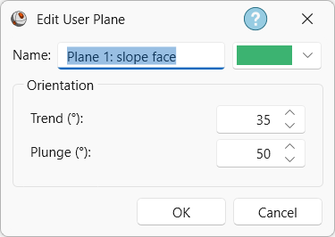
Edit User Plane dialog - Click OK to close the dialog and finalize the User Plane.
Plane 1: slope face will be created as shown below.
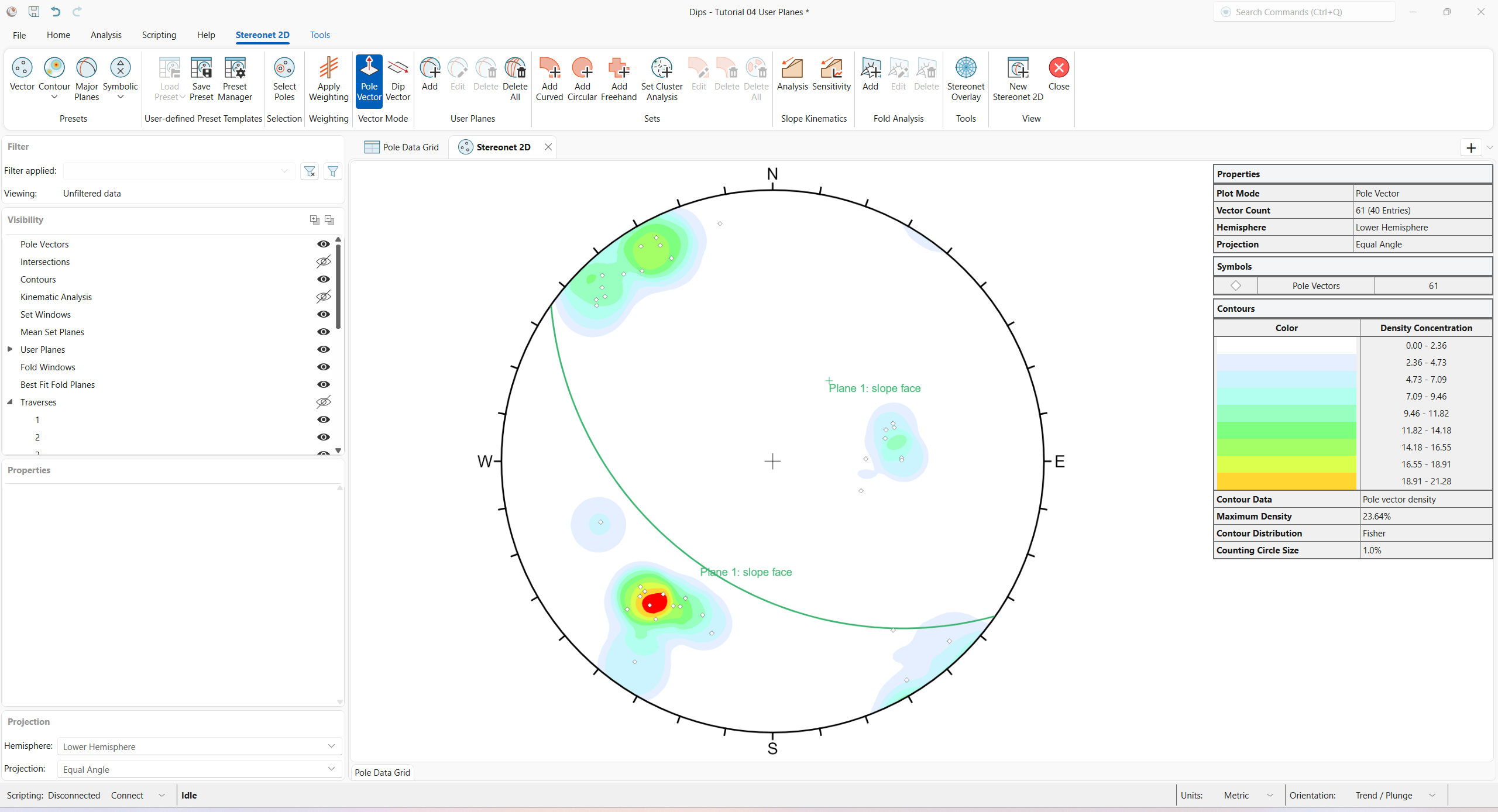
When the User Plane is created, you will notice the following, as shown in the above figure:
- The Plane 1: slope face User Plane is shown in the Stereonet 2D view.
- A Plane 1: slope face is added to the User Planes group in the Visibility tree.
5.1 Data Tips
If you hover the mouse over the User Plane, a pop-up data tip will display:
- User Plane
- Name = Plane 1: slope face
- Trend = 35
- Plunge = 50
The orientation is reported according to the selected Orientation reporting convention.
6.0 Properties
Various visibility and display properties can be customized in the Visibility and Properties panes for User Planes.
This concludes the tutorial. You are now ready for the next tutorial, Tutorial 05 – Qualitative and Quantitative Analysis.