10 - Bolt Application
1.0 Introduction
RocSlope3 can be used for block support design. This tutorial discusses the results interpretation tools that can be used to design mitigation as well as introduces several methods of bolt application.
The starting model consists of a highway cut without an application of bolts. This model will be computed to assess block stability and preliminary support requirements. Bolts will then be added to the model via the methods listed above.
Finished Product
The finished product of this tutorial can be found in the Tutorial 10 Bolt Application folder. All tutorial files installed with RocSlope3 can be accessed by selecting File > Recent Folders > Tutorials Folder from the RocSlope3 main menu.
2.0 Opening the Starting File
- Select File > Recent > Tutorials Folder.
- Go to the Tutorial 10 Bolt Application folder and open the file Tutorial 10 Bolt Application - starting file.rocslope_model.
The starting model consists of an unsupported highway cut without the application of bolts. This model will be computed to assess block stability and preliminary support requirements. Bolts will then be added to the model to stabilize blocks.
This model already has the following defined:
- Units
- External geometry
- Material Properties
- Synthetic Joints
- Joint Surface
- Joint Properties
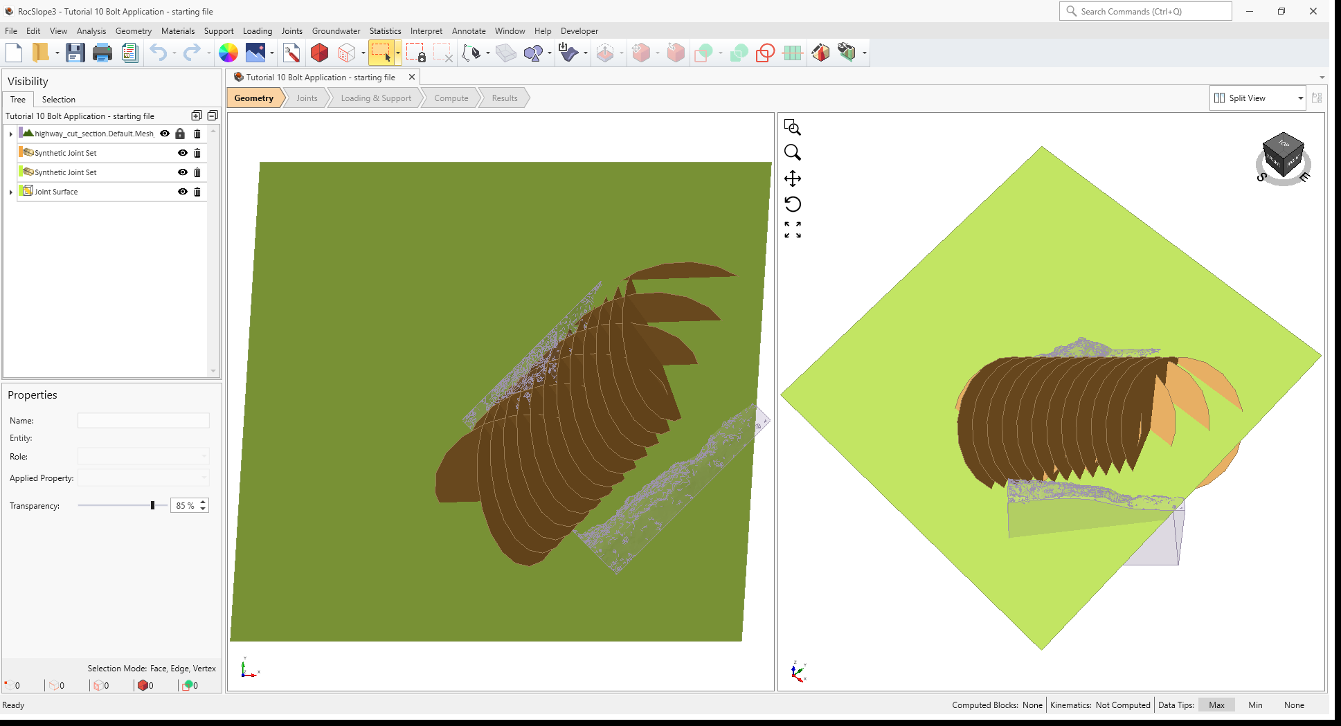
In the starting model, the external is defined by a section of a highway with steep, near-vertical rock slopes straddling both sides of the road.
The unsupported highway cut (without the application of bolts) will be computed to assess block stability and preliminary support requirements. Bolts will then be added to the model to stabilize blocks.
2.1 Project Settings
Review the Project Settings.
- Select Analysis > Project Settings

- Select the Units tab. Units are Metric, stress as MPa.
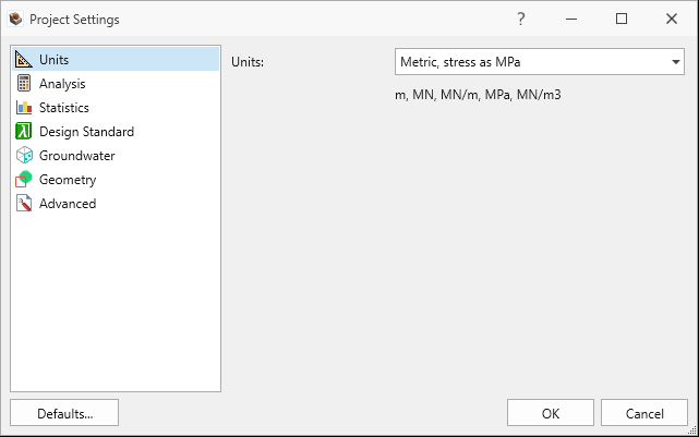
Units tab in Project Settings dialog - Select the Analysis tab.
- Design Factor of Safety = 1.5.
- Successive Failure is ON.
- Combined Blocks is OFF.
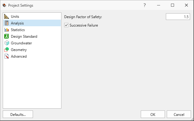
Analysis tab in Project Settings dialog - Click Cancel to exit the dialog.
2.2 Material Properties
Review the Material Properties.
- Select Materials > Define Materials

- One (1) material property is defined in the Define Materials dialog. The Rock material property has:
- Unit Weight = 0.026 MN/m3.
- Groundwater Method = Ru Coefficient.
- Ru Value = 0.4.
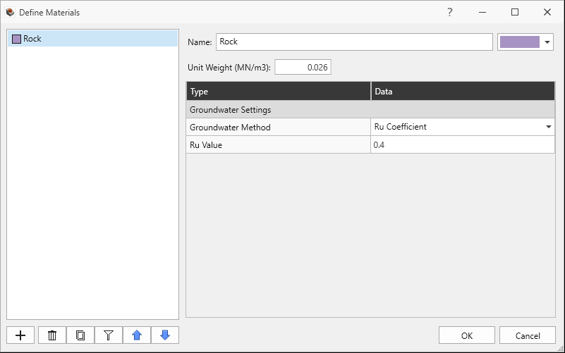
Define Materials dialog - Click Cancel to exit the dialog.
2.3 External Geometry
The External is of a highway section with vertical slope cuts on either side and composed of a single volume assigned with the Rock material property.
2.4 Joint Properties
Review the Joint Properties.
- Select Joints > Define Joint Properties
 . Two (2) joint properties are defined in the Define Joint Properties dialog.
 - The Shear joint property has the following Shear Strength inputs:
- Strength Type = Barton-Bandis
- JRC = 10
- JCS = 30 MPa
- Phir = 25 degrees
- Waviness = 0 degrees
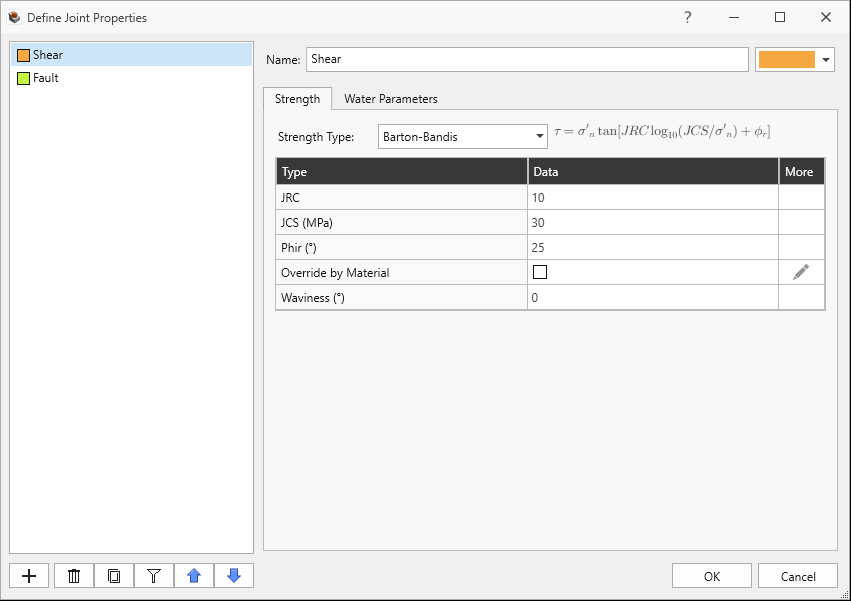
Shear Joint Property in Define Joint Properties dialog - Under the Water Parameters tab, Water Pressure Method = Material Dependent
- The Fault joint property has the following Shear Strength inputs:
- Strength Type = Mohr-Coulomb
- Cohesion = 0 MPa
- Phi = 30 degrees
- Waviness = 0 degrees
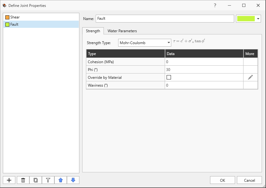
Fault Joint Property in Define Joint Properties dialog - Under the Water Parameters tab, Water Pressure Method = Material Dependent
- Click Cancel to exit the dialog.
2.5 Synthetic Joints
Review the Synthetic Joint Properties.
- Select Joints > Define Synthetic Joints
 . Two (2) synthetic joint properties are defined.
 - The Set 1 synthetic joint property has:
- Joint Property = Shear
- Joint Orientation Definition Method = Dip/Dip Direction
- Mean Dip = 60 degrees
- Mean Dip Direction = 85 degrees
- Mean Radius = 12 m
- Mean Spacing = 1.7 m
- Spacing Option = True Spacing
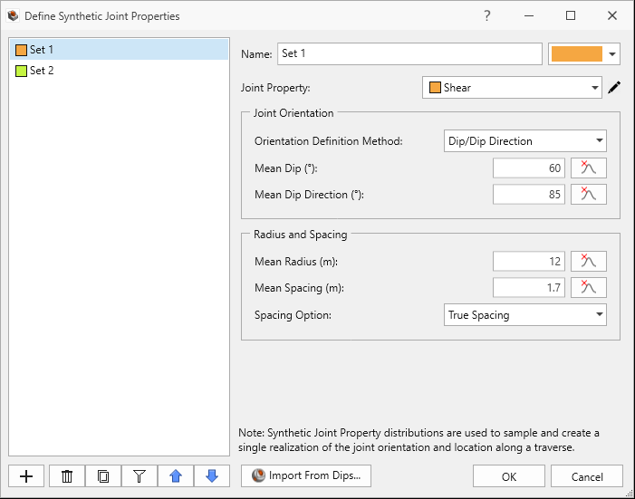
Set 1 Synthetic Joint Property in Define Synthetic Joint Properties dialog - The Set 2 synthetic joint property has:
- Joint Property = Shear
- Joint Orientation Definition Method = Dip/Dip Direction
- Mean Dip = 45 degrees
- Mean Dip Direction = 170 degrees
- Mean Radius = 12 m
- Mean Spacing = 2.4 m
- Spacing Option = True Spacing.
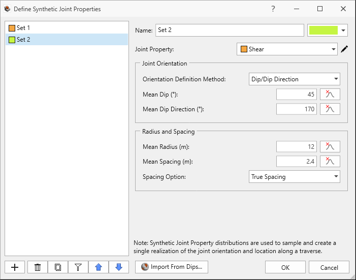
Set 2 Synthetic Joint Property in Define Synthetic Joint Properties dialog All parameters have no statistics assigned which means that the joints across the joint set will be parallel and constant in size and spacing. - Click Cancel to exit the dialog.
Both Synthetic Joint Sets traverse (data collected over a scanline) from:
- X = 13, Y = 15, Z = 1012 to
- X = -8, Y = -6, Z = 1012
2.6 Joint Surface
The planar Joint Surface is assigned with the Shear joint property.
3.0 Compute (Preliminary Assessment of Support Requirements from Unsupported Slope)
To compute the block and kinematic results:
- Navigate to the Compute workflow tab

- Select Analysis > Compute Blocks

- Select Analysis > Compute Kinematics

4.0 Interpreting Results
To view block stability results:
- Navigate to the Results workflow tab

- Select Results node in the Visibility Tree.
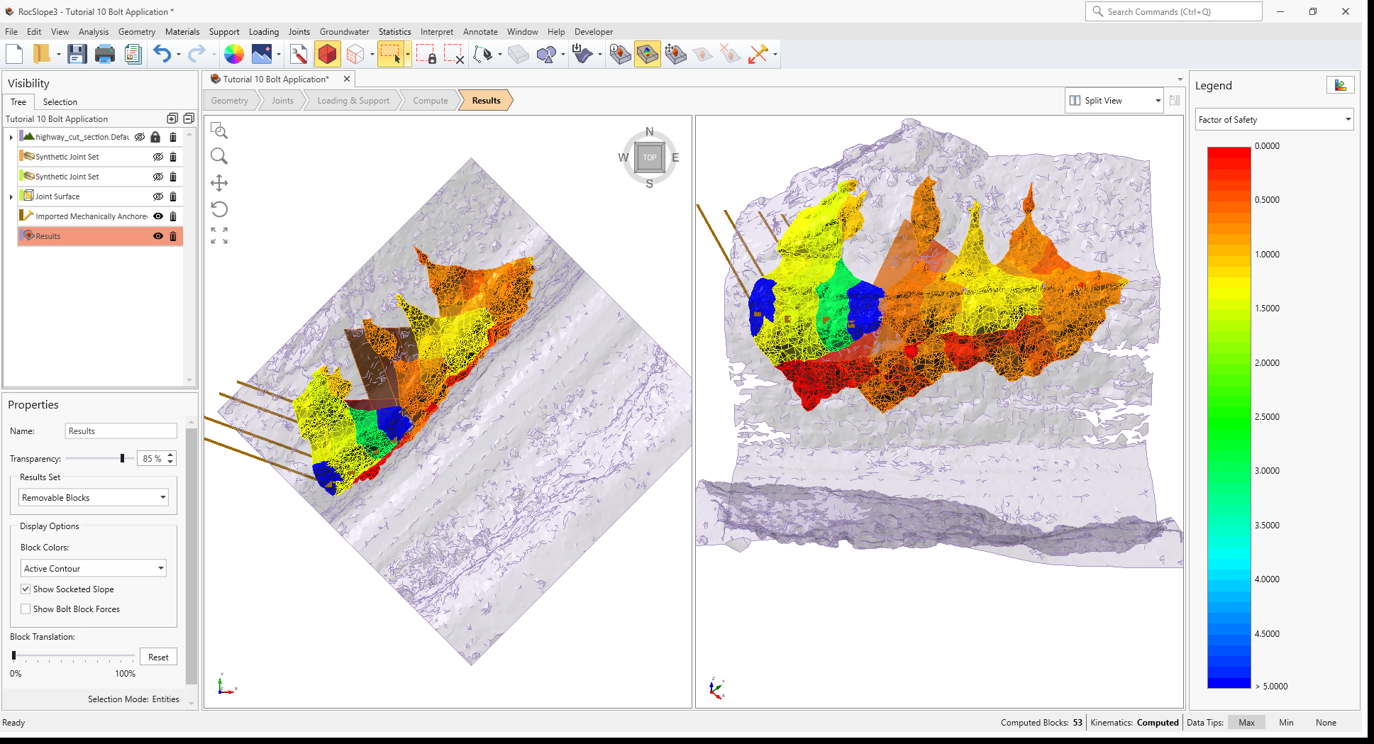
- Set the Results Set = Failed Unit Blocks (FS < Design FS). The unit blocks being displayed all have a Factor of Safety less than the Design Factor of Safety of 1.5.
- Select Interpret > Contour Blocks

- Set data to Factor of Safety. You should now see contours of Factor of Safety on the unit blocks, all less than 1.5.
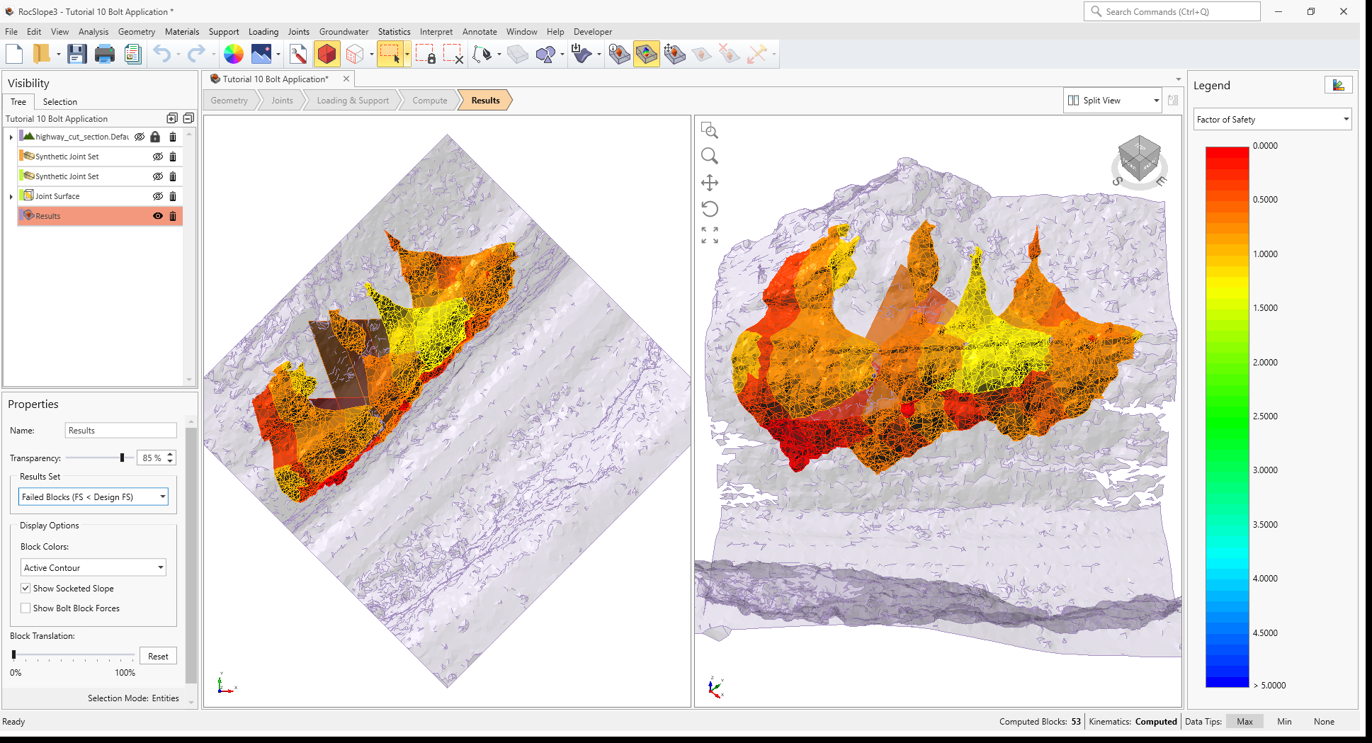
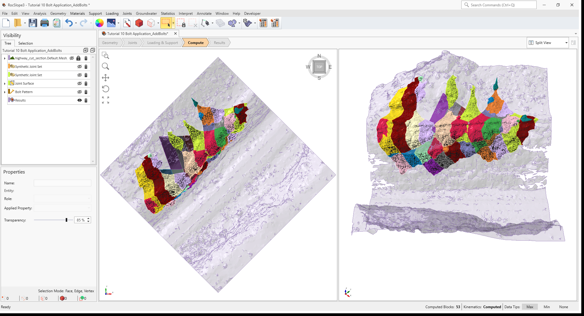
3D View of unsupported Failed Unit Blocks, contoured by Factor of Safety - Toggle the data drop down to Failure Iteration.
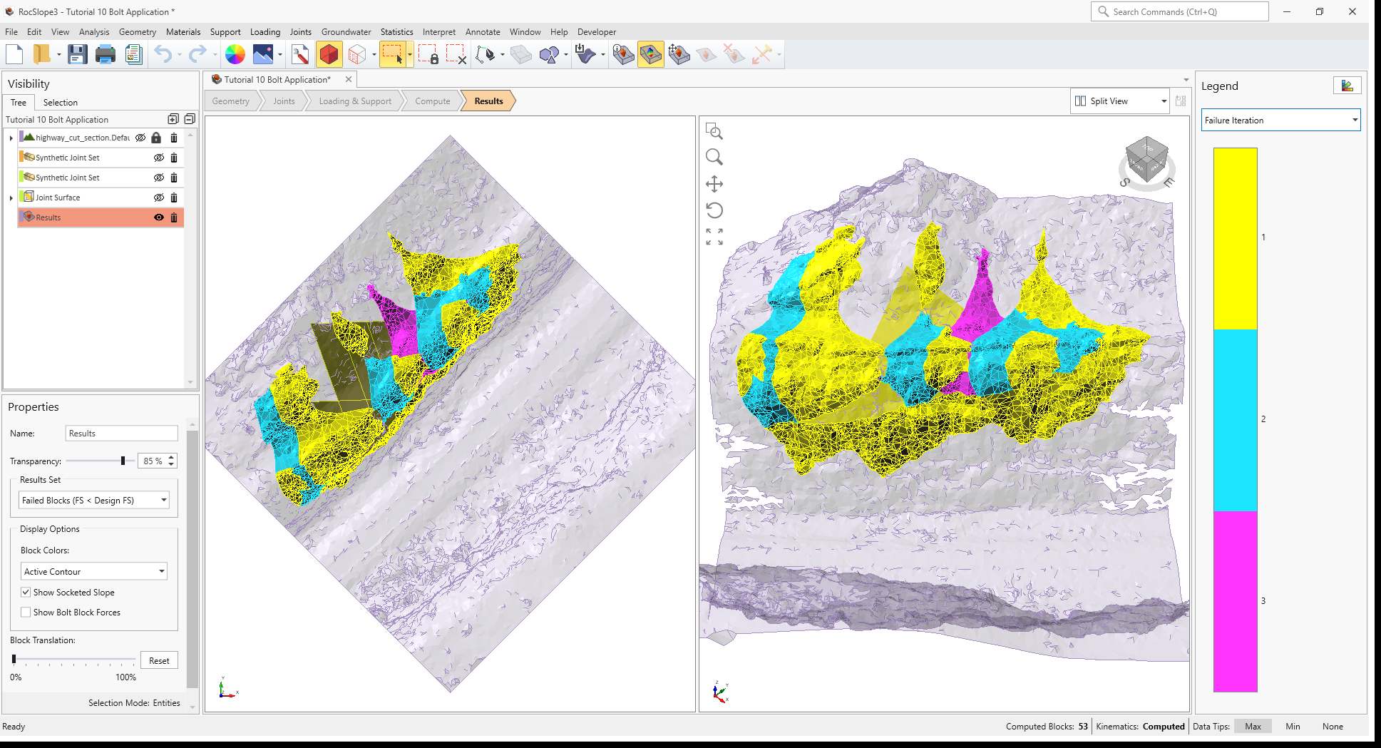
3D View of unsupported Failed Unit Blocks, contoured by Failure Iteration
The block contours should now show key blocks that failed in Failure Iteration 1 contoured in yellow. The detachment of key blocks (yellow) allow for adjacent unit blocks to fail in iterations 2 (cyan) and 3 (magenta).
5.0 Key Block Stabilization
Stabilizing a key block can help to stabilize any adjacent blocks that can fail with the release of the key block. Bolts can be added to stabilize the identified key blocks.
On the north-west end of the model, there are 4 large unit blocks (Block IDs 27, 3, 14, and 20) that were found to fail in iteration 1 and surrounds a unit block that was found to fail in iteration 2 (Block ID).
- Select Interpret > Block Information
 to view the computed block results for unit blocks with Factor of Safety less than 1.5.
 - Select View > Display Options

- Navigate to the Decimals tab.
- Set Loads = 4 decimal precision so that small force and pressure values not rounded to zero.
- Click OK.
- Note the Driving Force, Resisting Force, Sliding Direction Trend, Sliding Direction Plunge, Required Support Pressure, Slope Face Area, and Failure Depth values for Blocks 27, 3, 14, and 20.
- The Factor of Safety is determined by the ratio of Resisting Force / DrivingForce. In this model, the Driving Force is due to the weight of the block and water pressure forces in the joints. The Resisting Force is provided by the shear strength along sliding joints.
- The Sliding Direction is the direction of movement of the block. The most optimal bolt placement is in the direction of sliding so that the bolt acts in pure tension.
- The Required Support Pressure represents an average passive pressure applied in the normal direction into the block's daylighting face to obtain the Design Factor of Safety of 1.5.
- The Slope Face Area is the daylighting area of the block. Bolts can be applied to the daylighting face of a block.
- Failure Depth is the distance measured from the block's daylighting surface to the furthest failing block socket, in the normal direction of the block's daylighting face. The Failure Depth is a good indicator for choosing the length of bolts.
We’ll be importing bolts via a .csv file to anchor these key blocks, assuming a common bolt property for all four supports. The bolt requirement can be estimated:
- Typically, bolts are installed normal to the slope face at ±10 degrees and >45 degrees with respect to the joints (Choquet, 1987). Given the near-vertical slope, and the orientation of the joints present in the model, we can use a bolt plunge= 0 deg and a trend = 290 degrees.
- If a bolt force is being applied passively, it would increase the resisting force. This means we can estimate the required increase in resisting force for a FS = 1.5, summarized below.
- Block 27 requires 0.008 MN of additional resisting force
- Block 3 requires 0.276 MN of additional resisting force
- Block 14 requires 0.105 MN of additional resisting force
- Block 20 requires 0.027 MN of additional resisting force
- The largest additional required resisting force among the key blocks of interest is 0.28 MN on Block 3.
- The bolt length can be estimated from the failure depth (14.33 m for Block 3).
5.1 Define Bolt Property
To define a bolt property:
- Select Support > Define Bolt Properties

- Re-name Bolt Property 1 = Mechanically Anchored. This is to correspond with the Bolt Property name found in the bolt.csv file for bolt import.
- Set Support Type = Mechanically Anchored.
- Set Force Application = Passive. See the Active and Passive Force Application topic for more information.
- Set Use Bolt Orientation Efficiency = ON.
- Set Bolt Orientation Efficiency = Cosine Tension/Shear. See the Bolt Orientation Efficiency topic for more information.
- Set Tensile Capacity = 0.28 MN
- Set Plane Capacity = 0.28 MN
- Set Anchor Capacity = 0.28 MN
- Set Use Shear Capacity = ON
- Set Shear Capacity = 0.28 MN
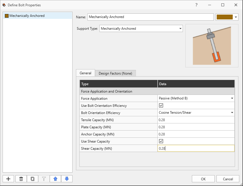
Mechanically Anchored Bolt Property in Define Bolt Properties dialog
- Click OK.
For mechanically anchored bolts, the minimum of the input tensile, plate, and anchor capacity is assumed to be the available tensile capacity applied uniformly over the bolt length. Bolt orientation efficiency is considered, meaning that the tensile capacity can be reduced depending on the relative orientation of the block's sliding direction. Finally, the bolt shear capacity is being used, and it is mobilized under deformation modes involving bolt shearing. See the Mechanically Anchored Bolts topic for more information.
5.2 Import Bolts from CSV File
Inspect the bolts.csv file
provided. The bolt installation information for each bolt's geometry
(Start Point, Orientation, and Length) and assigned Bolt Property is
listed in the bolts.csv file.
To import bolts from csv:
- Select Support > Import Bolts from CSV File

- In the Import Bolts From CSV dialog:
- Select Browse and open the bolts.csv file.
- Set Define Bolt Geometry By = Start Point, Orientation and Length
- Set Orientation = Trend and Plunge
- Select Import Bolt Properties checkbox.
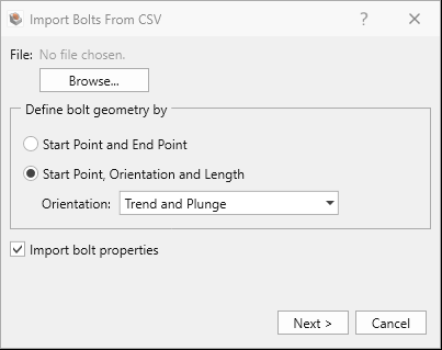
File selection in Import Bolts From CSV dialog - Click Next.
- Under Row Setup:
- Set Delimiter = Comma
- Set Start Row = 2 to skip the header row.
- Under Column Setup:
- Set Start X = 1
- Set Start Y = 2
- Set Start Z = 3
- Set Trend = 4
- Set Plunge = 5
- Set Length = 6
- Set Bolt Property =7
- Inspect the data in the Data Preview:

Row and Column setup in Import Bolts From CSV dialog - Click Next.
- Enter Name = Imported Mechanically Anchored Bolts.
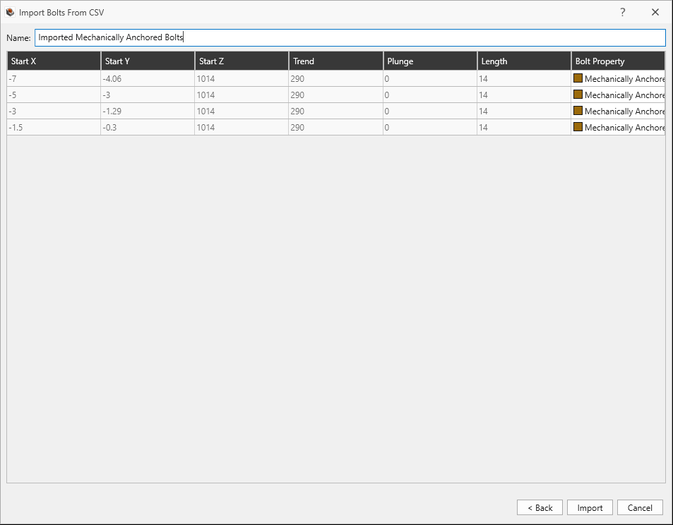
Import Bolts from CSV dialog - Click Import.
- A message "All 4 bolts are successfully imported" pops up. Click OK.
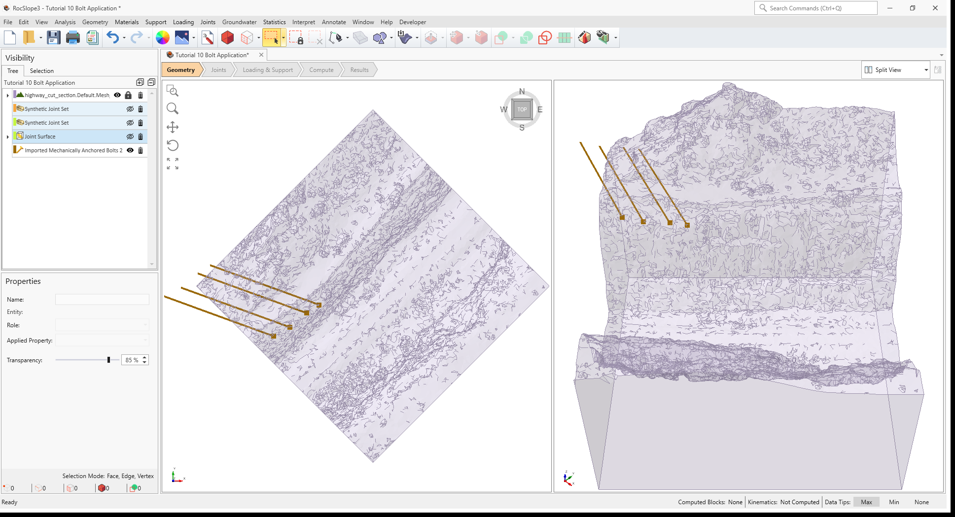
- In the Visibility tree, select the Imported Bolts node, and then select Support > Snap Imported Bolts in the menu to ensure bolts are snapped to the surface. See the Snap Imported Bolts topic for more information on bolt snapping.
- To better see the bolts, hide the joint entities in the Visibility Tree.
Four
imported bolts have been added to the model and the Imported
Mechanically Anchored Bolts node is added to the Visibility Tree.
6.0 Compute (Imported Bolts)
To compute the block and kinematic results:
- Navigate to the Compute workflow tab
- Select Analysis > Compute Blocks
- Select Analysis > Compute Kinematics
7.0 Interpreting Results
To view block stability results:
- Navigate to the Results workflow tab
- Select Results node in the Visibility Tree.
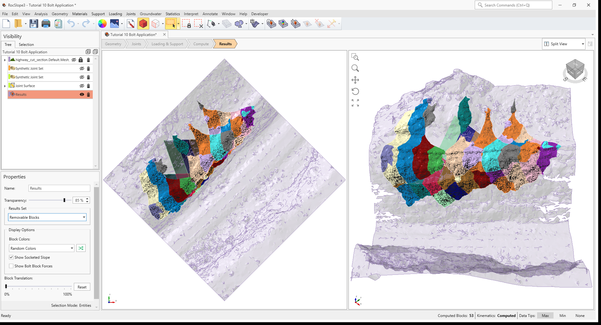
- Select Results Set = Removeable Unit Blocks.
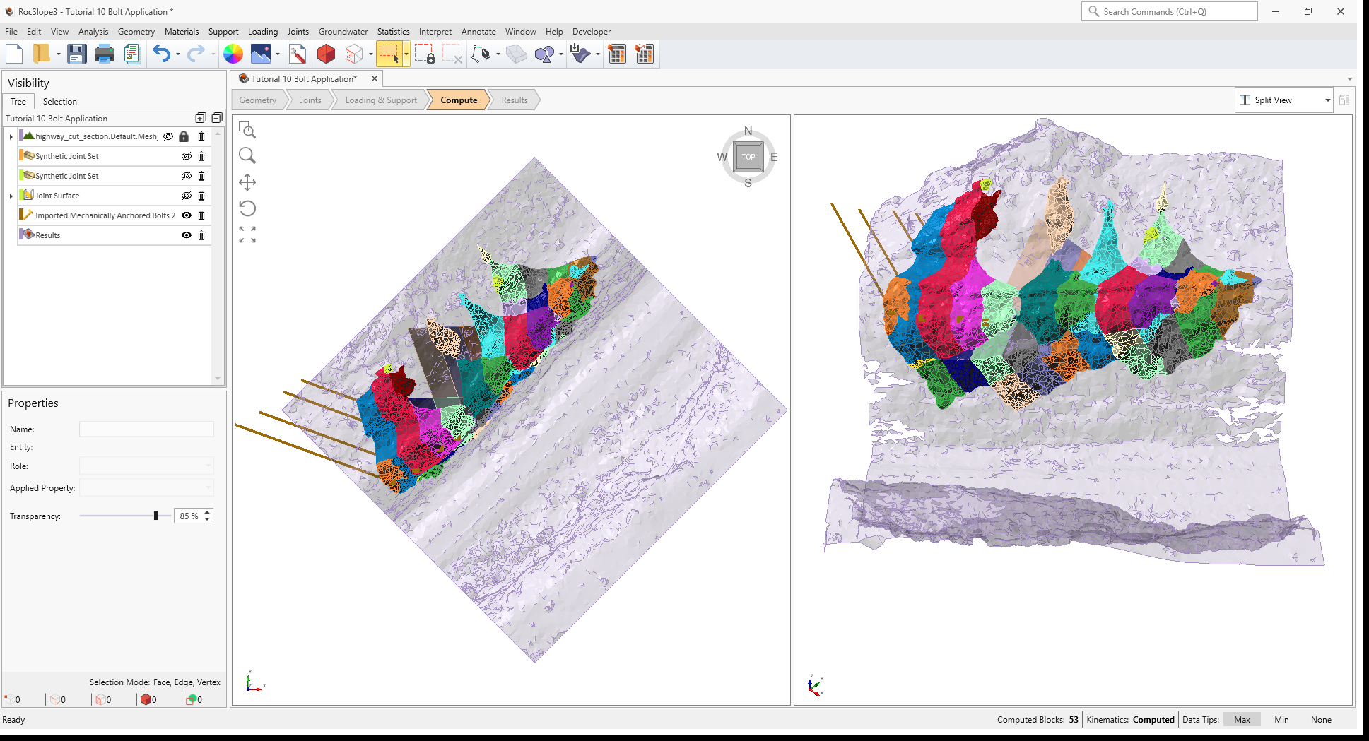
- Select Interpret > Contour Blocks
- Set the data to Factor of Safety. You should now see contours of Factor of Safety on the unit blocks.
The unit blocks that are anchored now have much larger factors of safety. Block ID = 3, which controlled the bolt capacity requirement, now has a factor of safety that is very close to 1.5.
Save the model file as Bolt Application_import bolts.rocslope_model.
8.0 Add Bolts to Selected Surfaces
The Add Bolts to Selected option for bolting is convenient for bolt installation in difficult geometries, such as near vertical slopes or overhangs. We’ll use this method to install a bolt pattern over the entire span of the near-vertical slope face.
Before bolt installation, let’s determine a feasible bolt pattern based on the required support pressure of unstable unit blocks on the unsupported slope face.
- Select File > Recent > Tutorials Folder.
- Go to the Tutorial 10 Bolt Application folder and open the file Tutorial 10 Bolt Application - starting file.rocslope_model.
- If not already computed, navigate to the Compute workflow tab:
- Select Analysis > Compute Blocks
- Select Analysis > Compute Kinematics
- Select Analysis > Compute Blocks
- Navigate to the Results workflow tab
- Select Interpret > Contour Blocks
- Set the data to Required Support Pressure to display contours of the required support pressure to achieve the Design Factor of Safety.
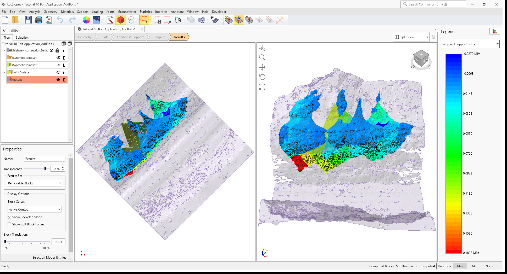
The largest requirement appears to be approximately 0.18 MPa (Block 7). Assuming a capacity of 0.6 MN in each bolt, we would need approximately 0.6 MN / 0.18 MPa = 1 bolt per 3.33 m2. If we use a square array bolt pattern, then we would require a bolt spacing no greater than of 1.8 m by 1.8 m. Use 1.5 m spacing as a practical installation value.
Let’s install a pattern of simple bolt forces in a square array of 1.5 m spacing across the entire vertical slope face.
- Select Interpret > Clear Results
- To better see the slope geometry, hide all other entities, such as the joints in the Visibility Tree.
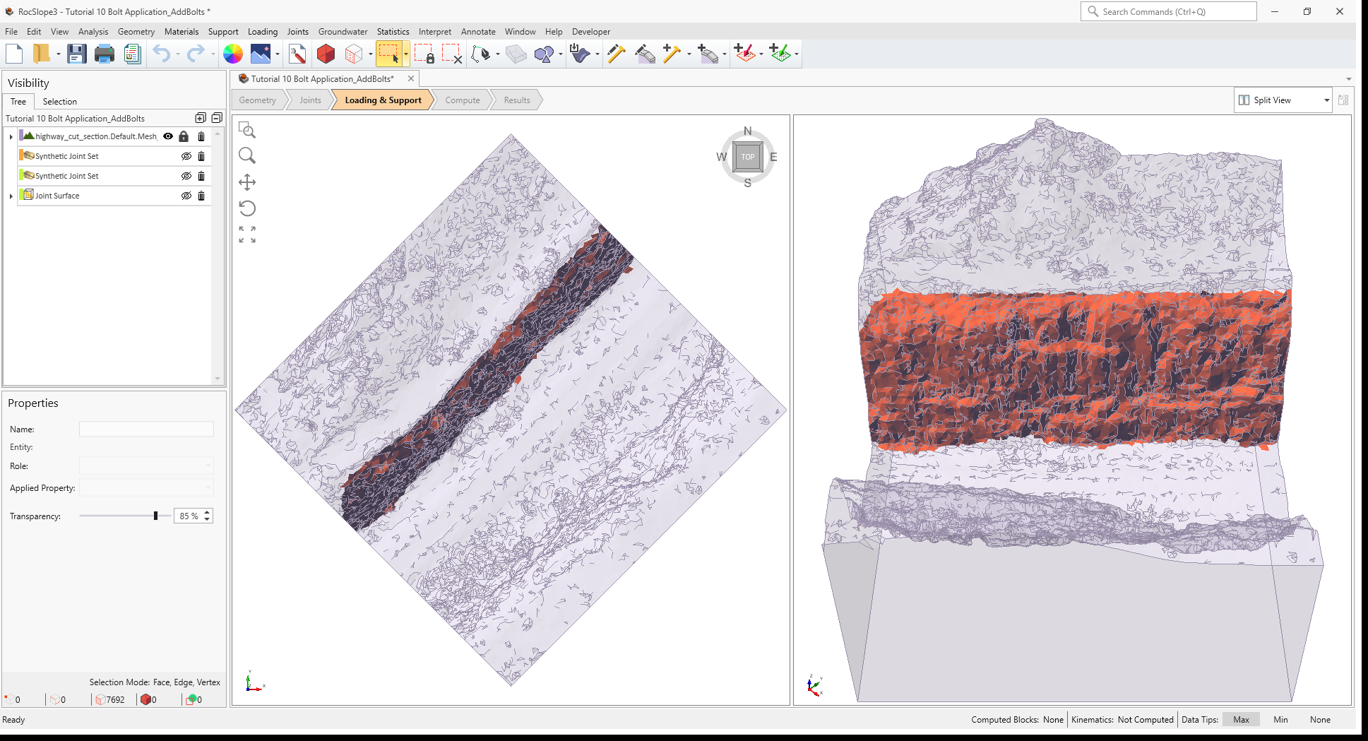
- Select Edit > Selection Mode > Face Selection

- Select Edit > Selection Region Mode > Lasso Selection
 . Lasso selection works by left-clicking and dragging the cursor over the area of interest.
 - Select the vertical portion of the slope faces on the north side.
- Zoom in/out to check for gaps in the selection, and select any unselected faces by holding CTRL and left-clicking.
To add bolts to the selected surface:
- Select Support > Add Bolts to Selected Surface

- In the Add Bolts dialog, select Edit Bolt Property button

- In the Define Bolt Properties dialog:
- Set Support Type = Simple Bolt Force
- Set Force Application = Passive
- Set Force = 0.6 MN

Simple Bolt Force bolt property in Define Bolt Properties dialog - Click OK.
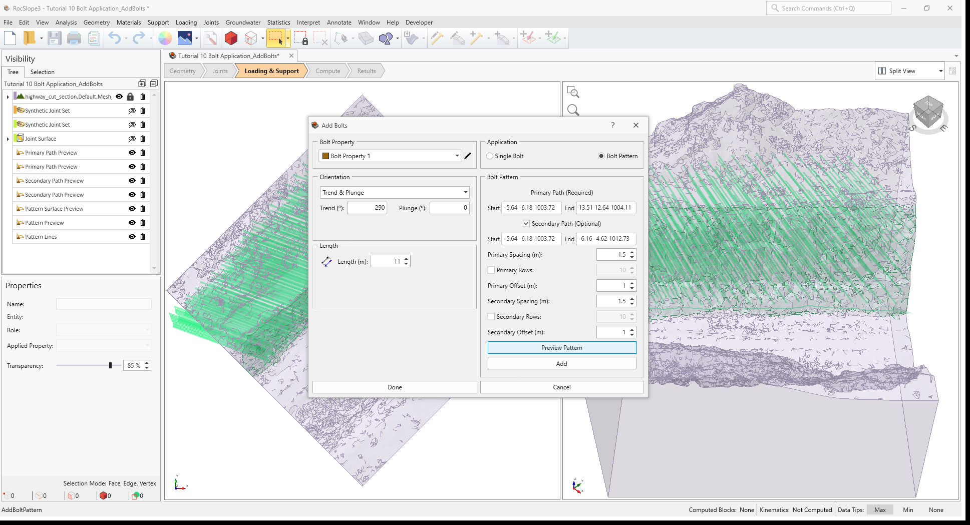
- Under Orientation:
- Set Orientation = Trend & Plunge
- Set Trend = 290 degrees
- Set Plunge = 0 degrees
- Set Length = 11 m
- Set Application = Bolt Pattern
- Under Bolt Pattern:
- Set Primary Path Start = -5.64 -6.18 1003.72 and End = 13.51 12.64 1004.11
- Select Secondary Path checkbox.
- Set Primary Path Start = -5.64 -6.18 1003.72 and End = -6.16 -4.62 1012.73
- Set Primary Spacing = 1.5 m
- Set Primary Offset = 1 m
- Set Secondary Spacing = 1.5 m
- Set Secondary Offset = 1 m.
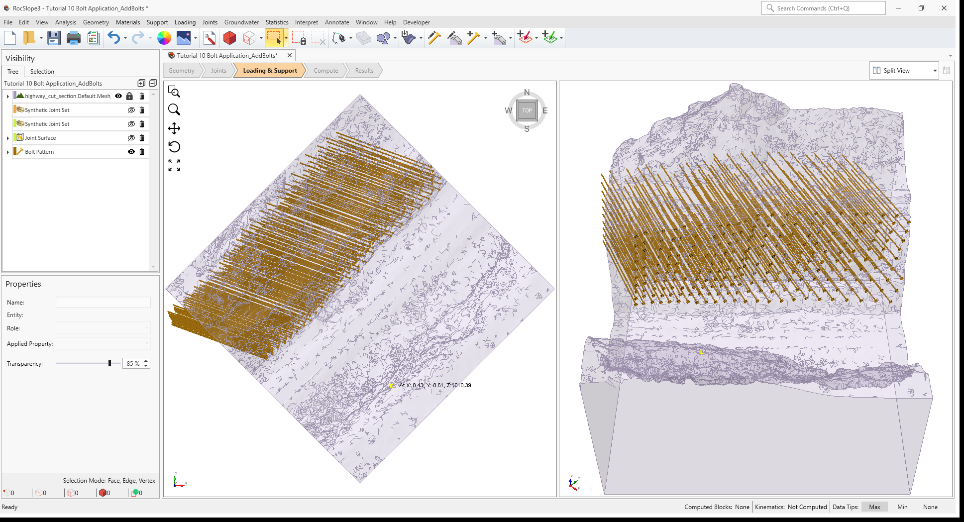
- Select Preview Pattern button to preview the bolt pattern.
- Click Add to add the bolt pattern to the mode.
- Click OK to exit the dialog.
The bolt pattern is added to the model and the Bolt Pattern node is added to the Visibility Tree.
9.0 Compute (Add Bolts to Selected Surface)
To compute the block and kinematic results:
- Navigate to the Compute workflow tab
- Select Analysis > Compute Blocks
- Select Analysis > Compute Kinematics
10.0 Interpreting Results
To view block stability results:
- Navigate to the Results workflow tab
- Select Results node in the Visibility Tree.
- Select Interpret > Contour Blocks
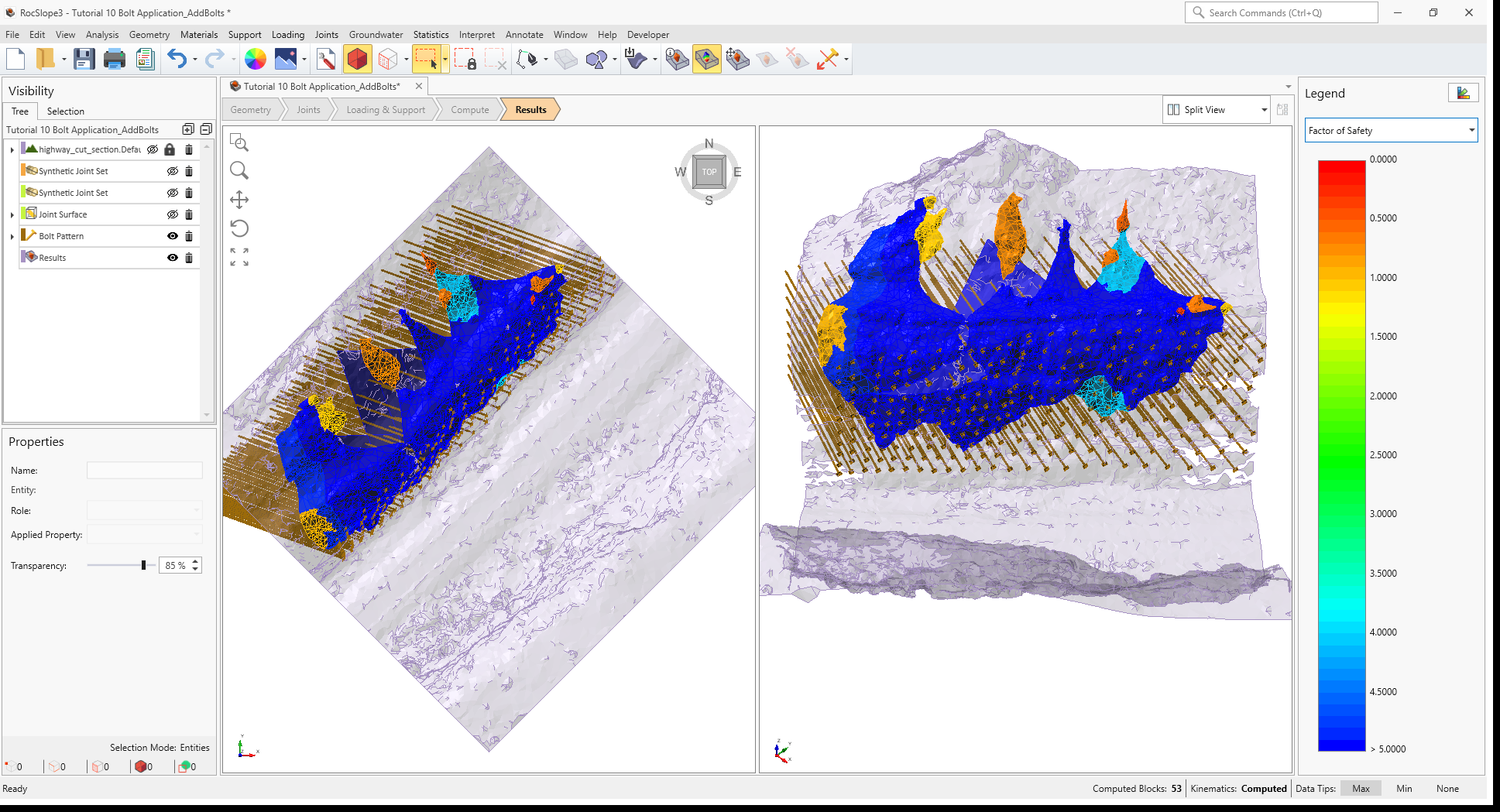
- Set the data to Factor of Safety. You should now see contours of Factor of Safety on the unit blocks.
The Factors of Safety are greatly increased for supported unit blocks.
This concludes Tutorial 10.