4 - Search Limits
1.0 Introduction
In RocSlope3, Search Limits can be used to constrain the search region during Compute Blocks. This can be done by either including specified volumes of interest and/or excluding specified volumes to prevent blocks from forming in unwanted regions of the model.
Finished Product
The finished products of this tutorial - Tutorial 04 Search Limits - auto limit.rocslope_model, Tutorial 04 Search Limits - box limit.rocslope_model, and Tutorial 04 Search Limits - arbitrary volume limit.rocslope_model - can be found in the Tutorial 04 Search Limits folder. All tutorial files installed with RocSlope3 can be accessed by selecting File > Recent Folders > Tutorials Folder from the RocSlope3 main menu.
2.0 Opening the Starting File
- Select File > Recent > Tutorials Folder in the menu.
- Go to the Tutorial 04 Search Limits folder and open the file Tutorial 04 Search Limits - starting file.rocslope_model.
This model already has the following defined and provides a good starting point to start defining search limits:
- Project Settings
- Material Properties
- External Geometry
- Joint Properties
- Measured Joints
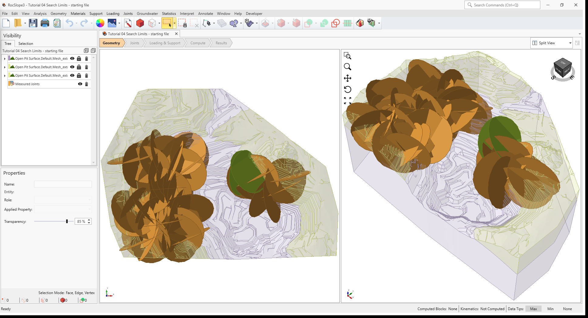
In the starting model, Measured Joints are defined over the west and northeast extents of open pit.
For this tutorial, we will apply different types of Search Limits to constrain the blocks formed to specific regions of the open pit. In RocSlope3, there are three types of Search Limits:
- Box Search Limits
- Arbitrary Volume Search Limits
- Auto Search Limits
Additionally, there are two types of constraints that can be applied on a Search Limit:
- Completely Inside – blocks admitted during the compute must be completely inside the defined region.
- Completely Outside – no part of the blocks admitted during the compute shall be inside or touch the defined region.
2.1 Project Settings
Review the Project Settings.
- Select Analysis > Project Settings

- Select the Units tab. Ensure Units are Metric, stress as
MPa.
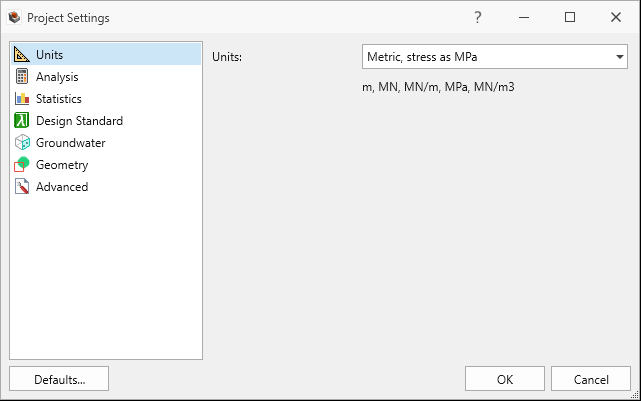
Units tab in Project Settings dialog - Select the Analysis tab.
- Ensure Design Factor of Safety = 1.2.
- Ensure Successive Failure is OFF.
- Ensure Combined blocks is OFF.
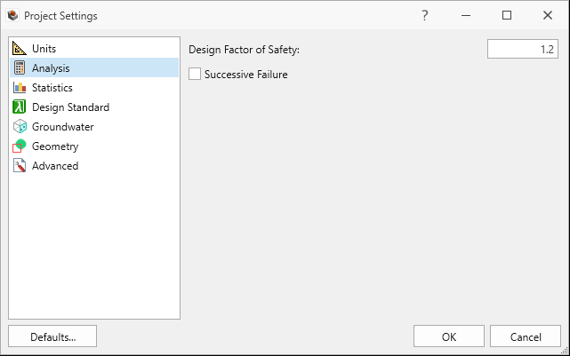
Analysis tab in Project Settings dialog
- Click Cancel to exit the dialog.
2.2 Material Properties
Review the Material Properties.
- Select Materials > Define Materials
 . Two (2) material properties are already defined.
 - The Schist material property has:
- Unit Weight = 0.026 MN/m3.
- No Water Surface applied.
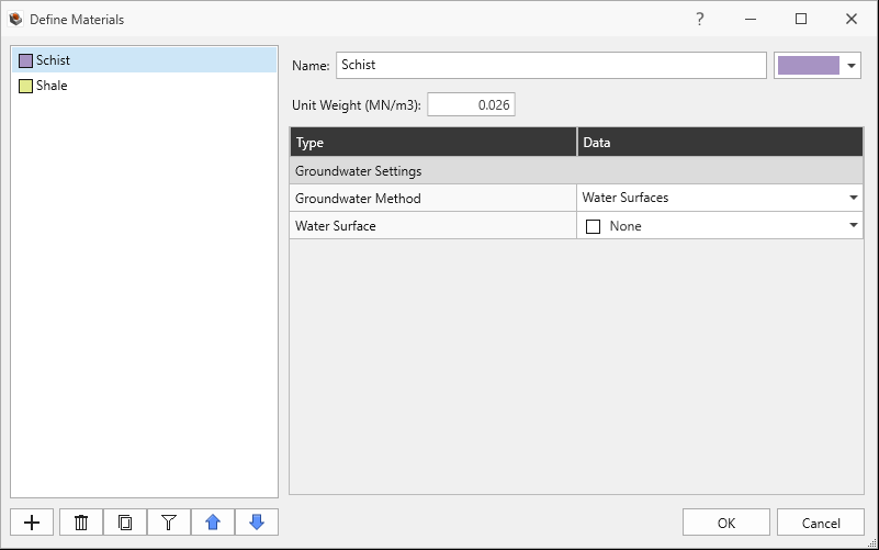
Schist Material Property in Define Materials dialog
- The Shale material property has:
- Unit Weight = 0.0265 MN/m3.
- No Water Surface applied.
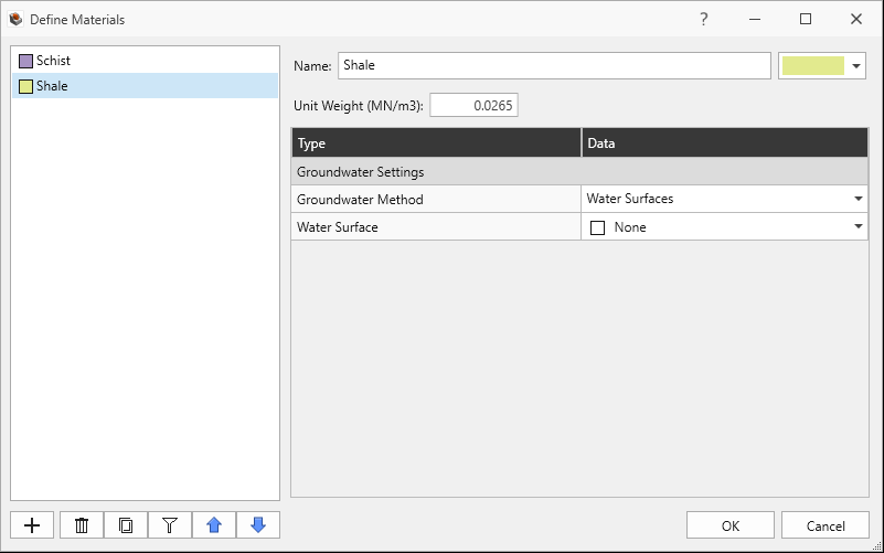
Shale Material Property in Define Materials dialog
- Click Cancel to exit the dialog.
2.3 External Geometry
The External is of a pit shell and composed of three volumes. The lower volume (Open Pit
Surface.Default.Mesh_extruded_1) is assigned with the Schist material property. The
upper volumes (Open Pit Surface.Default.Mesh_extruded_2, Open Pit
Surface.Default.Mesh_extruded_3) are assigned with the Shale material property.
2.4 Joint Properties
Review the Joint Properties.
- Select Joints > Define Joint Properties
 . Two (2) joint properties are defined.
 - The Smooth joint property has:
- Strength Type = Mohr-Coulomb
- Cohesion = 0 MPa
- Phi = 10 degrees
- Waviness = 0 degrees
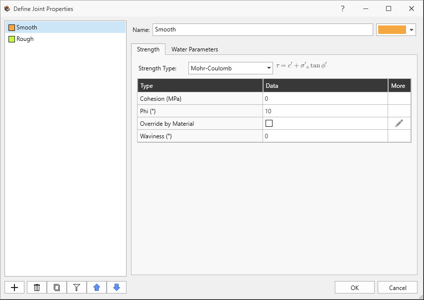
Smooth Joint Property Strength tab in Joint Properties dialog - Water Pressure Method = Dry
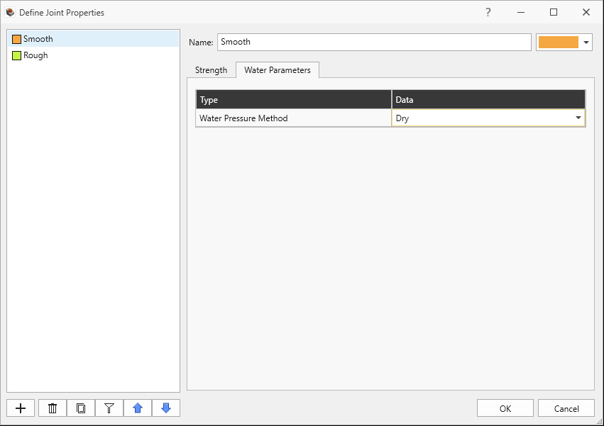
Smooth Joint Property Water Parameters tab in Define Joint Properties dialog
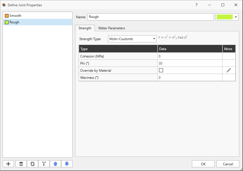
- The Rough joint property has:
- Strength Type = Mohr-Coulomb
- Cohesion = 0 MPa
- Phi = 30 degrees
- Waviness = 0 degrees
- Water Pressure Method = Dry
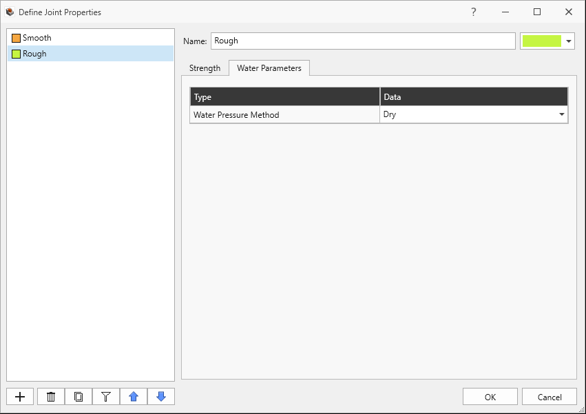
Rough Joint Property Water Parameters tab in Define Joint Properties dialog
Rough Joint Property Strength tab in Define Joint Properties dialog - Click Cancel to exit the dialog.
2.5 Measured Joints
Review the Measured Joints.
Select Joints > Define Measured Joints

63 Measured Joints are defined and listed in order of Dip, Dip Direction, X, Y, Z, Radius, and Joint Property.
Dip Dip Direction X Y Z Radius Joint Property 17 101 -362 -432 1012 200 Smooth 10 249 -511 -162 1042 200 Smooth 19 343 -631 112 1066 200 Smooth 45 58 -789 -329 1098 200 Smooth 26 213 -628 60 1066 200 Smooth 84 351 -516 -421 1043 200 Smooth 51 162 -339 -320 1008 200 Smooth 49 178 -253 -309 991 200 Smooth 77 291 -403 114 1021 200 Smooth 54 51 -417 -421 1023 200 Smooth 24 122 -591 -584 1058 200 Smooth 41 49 -643 -393 1069 200 Smooth 31 217 -436 -142 1027 200 Smooth 74 48 -628 -313 1066 200 Smooth 76 295 -622 -578 1064 200 Smooth 48 273 -691 -451 1078 200 Smooth 22 335 -655 -307 1071 200 Smooth 53 224 -598 -532 1060 200 Smooth 63 107 -336 -320 1007 200 Smooth 47 106 -319 -542 1004 200 Smooth 24 124 -487 143 1037 200 Smooth 28 226 -632 -556 1066 200 Smooth 26 330 -730 -363 1086 200 Smooth 45 216 -333 -517 1007 200 Smooth 36 221 -321 -473 1004 200 Smooth 32 216 -667 -565 1073 200 Smooth 57 101 -342 -147 1008 200 Smooth 30 312 -305 182 1001 200 Smooth 74 112 -373 80 1015 200 Smooth 52 103 -379 -564 1016 200 Smooth 33 86 -263 160 993 200 Smooth 42 108 -563 -446 1053 200 Smooth 36 68 -325 -340 1005 200 Smooth 43 80 -467 -103 1033 200 Smooth 40 74 -546 150 1049 200 Smooth 54 79 -374 -140 1015 200 Smooth 81 323 -275 82 995 200 Smooth 45 85 -412 -24 1022 200 Smooth 15 316 -555 -208 1051 200 Smooth 90 356 -488 -130 1038 200 Smooth 81 349 -788 134 1098 200 Smooth 37 235 -289 40 998 200 Smooth 29 117 -337 134 1007 200 Smooth 84 337 -271 -550 994 200 Smooth 71 79 -532 196 1046 200 Smooth 66 121 -752 -293 1090 200 Smooth 32 335 -611 -180 1062 200 Smooth 50 129 -580 -369 1056 200 Smooth 57 101 -511 17 1042 200 Smooth 48 91 -718 73 1084 200 Smooth 25 125 -528 -60 1046 200 Smooth 43 80 -466 -251 1033 200 Smooth 33 73 -366 -575 1013 200 Smooth 47 65 -452 -90 1030 200 Smooth 83 336 -694 -588 1079 200 Smooth 57 101 200 12 1042 200 Rough 48 60 250 20 1084 200 Rough 25 125 251 -20 885 200 Smooth 43 80 350 -30 905 200 Smooth 33 73 574 -60 964 200 Smooth 47 65 248 -32 945 200 Smooth 83 336 300 -27 999 200 Smooth 81 349 600 -20 959 200 Smooth 37 235 346 -20 953 200 Smooth 29 117 577 -60 900 200 Smooth 84 337 532 -130 894 200 Smooth 71 79 459 -230 946 200 Smooth 66 121 383 -200 940 200 Smooth 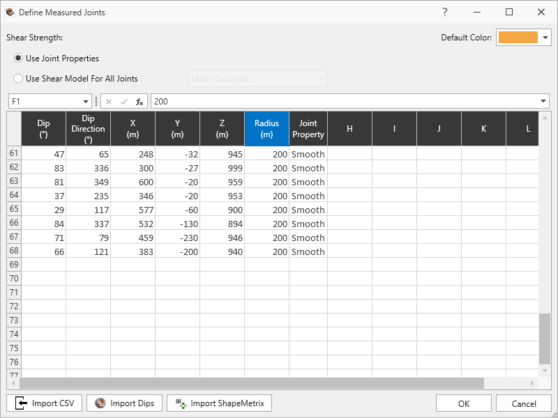
68 Measured Joints defined in Define Measured Joints dialog - Click Cancel to exit the dialog.
3.0 Compute (without Search Limits)
First let's compute unit blocks without adding any Search Limits.
3.1 Compute Blocks
To compute the unit blocks:
- Navigate to the Compute workflow tab

- Select Analysis > Compute Blocks

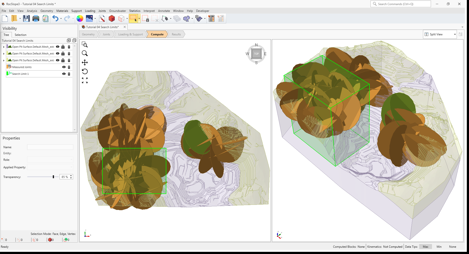
As compute is run, the progress bar reports the compute status. Once compute is finished, the Results node is added to the Visibility Tree and valid unit blocks are shown in the viewport. The Results node consists of the collection of valid unit blocks and the socketed slope. The original External and Measured Joints visibility is turned off.
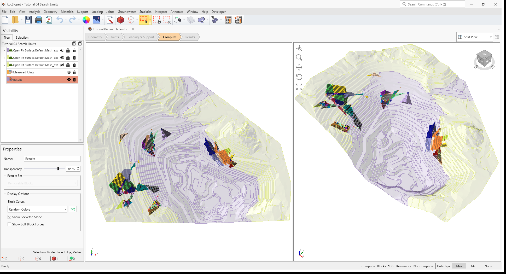
Without any Search Limits defined, the entire External and all Joints are considered when computing unit blocks.
For models with large External and many Joints, computing the entire External and all Joints can be
resource-intensive. Consider using Search Limits to narrow down the compute region.
4.0 Auto Search Limits
The Auto Search Limits option in RocSlope3 automatically determines the regions of interest based on where joints are clustered. The logic behind Auto Search Limits is that if a single joint or joint from a cluster of joints can daylight on the external, then it has the potential of forming blocks which can daylight over that region.
To compute the Auto Search Limits:
- Select Analysis > Search Limits > Auto Search Limits

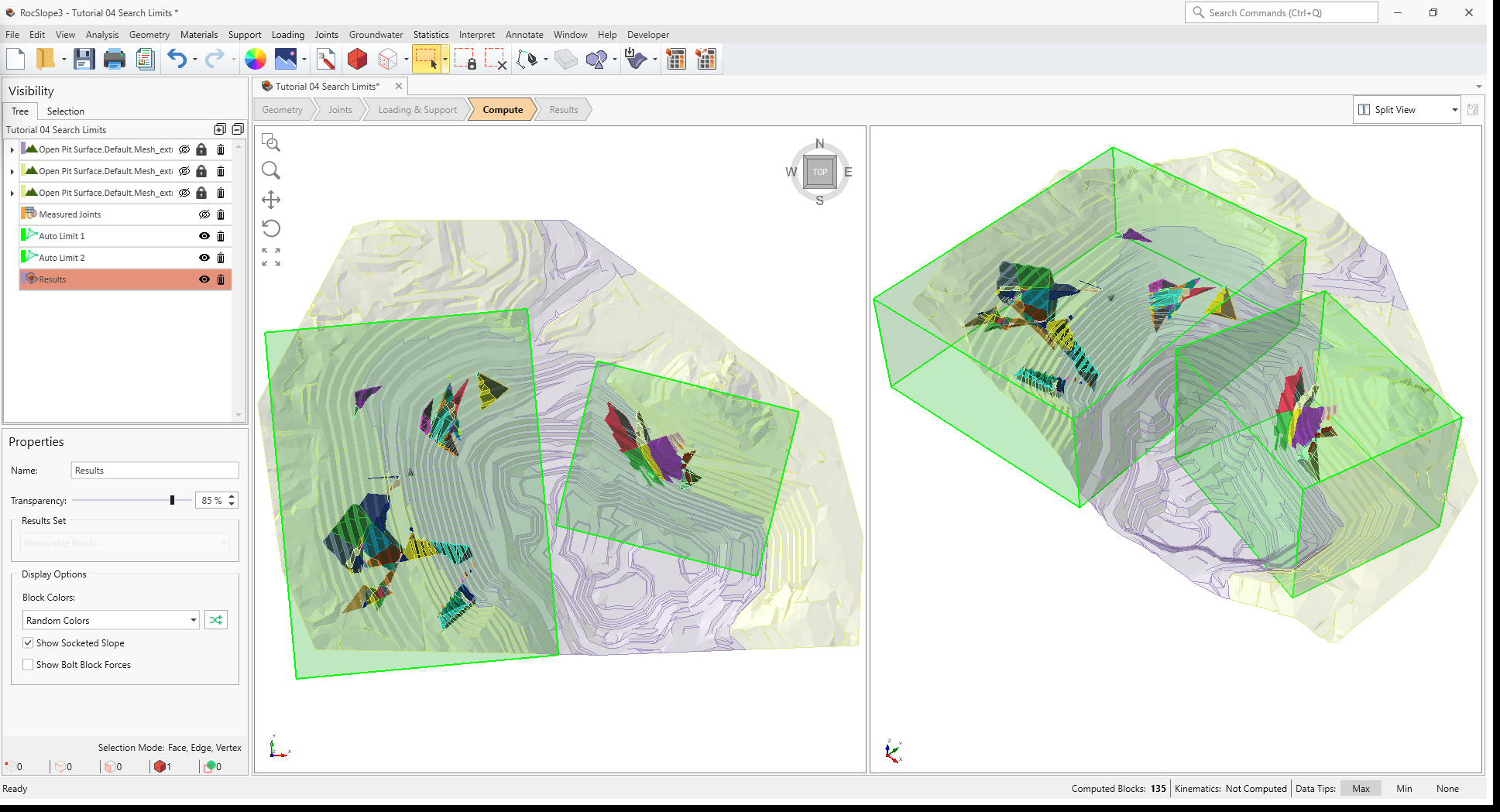
- Two Search Limits are automatically added to the model:
- Auto Limit 1 contains the XY and bottom extents of the joints from the west joint cluster, and top extents of the External geology.
- Auto Limit 2 contains the XY and bottom extents of the joints from the east joint cluster, and top extents of the External geology.
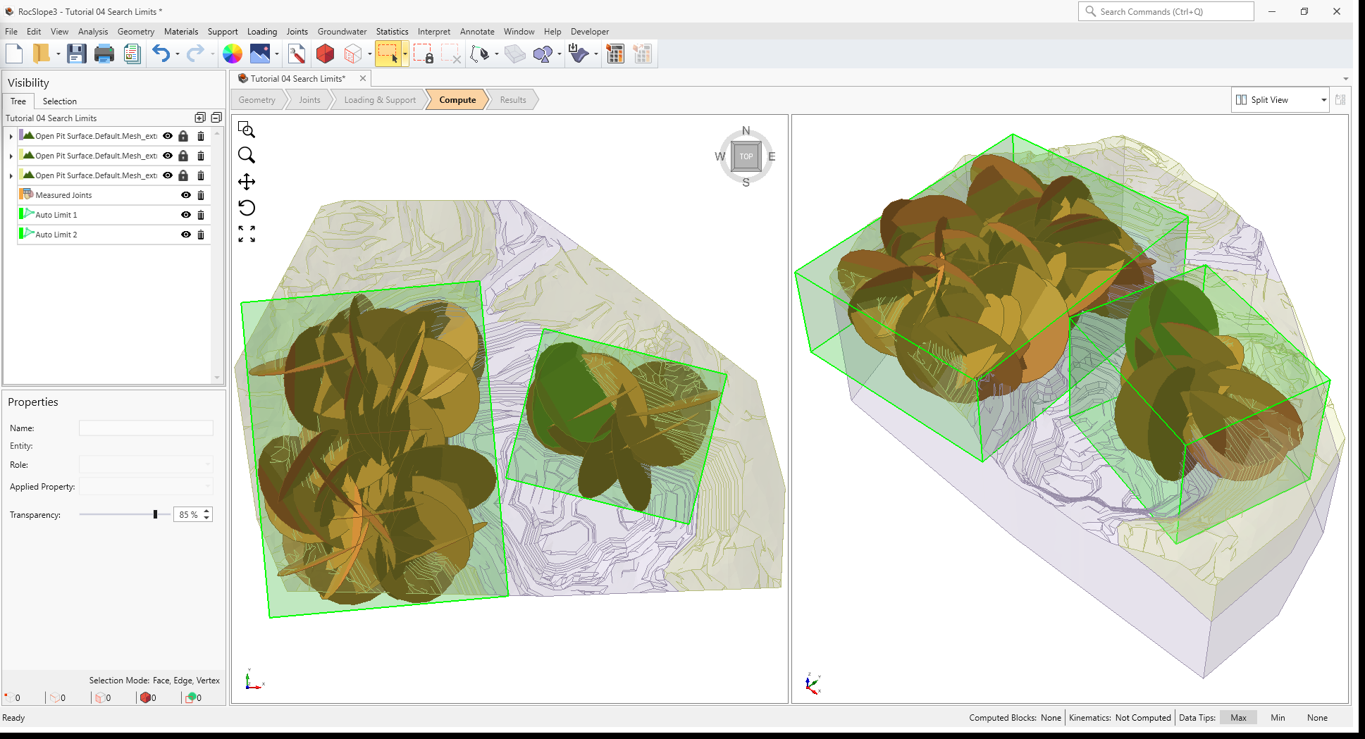
Auto Limits are volumetric search regions where any blocks inside (but not touching) the search volume is considered valid.
5.0 Compute (with Auto Search Limits)
Now let's compute unit blocks with the Auto Search Limits.
5.1 Compute Blocks
- Ensure you are still in the Compute workflow tab
- Select Analysis > Compute Blocks
The same set of block results as before is computed since all regions with joints are being considered.
Now, delete the Auto Search Limits:
- Select Auto Limit 1 node from the Visibility Tree.
- Click the Delete
 button.
 - Select Auto Limit 2 node from the Visibility Tree.
- Click the Delete button.
6.0 Add Search Limit By Box
If we wanted to only consider the southwest region, we could reduce the valid search region by adding a Box as the search region.
To add a box search limit:
- Select Analysis > Search Limits > Add Search Limit by Box
- The Create Search Limit Area dialog allows the user to define the extents of the Box Search
Limit.
- Set Defined By = 2 Corners.
- Set the Box Corners:
- First Corner X = -800, Y = -600, Z = 500.
- Second Corner X = -100, Y = -100, Z = 1300.
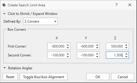
Create Search Limit Area dialog
- Click OK.
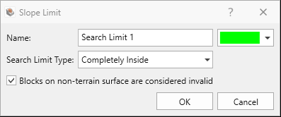
- In the Slope Limit dialog:
- Set Name = Search Limit 1.
- Set Search Limit Type = Completely Inside.
- Select Blocks on non-terrain surface are considered invalid.
 The non-terrain surface includes the bottom and sides of the model and are automatically determined by RocSlope3. Any blocks (unit or combined) touching the non-terrain surface is considered invalid to prevent blocks from coming out of the bottom and side of the model. For some slope geometries such as vertical or overhanging sides of the models which should actually be considered as a valid daylighting surface, the non-terrain surface may not be automatically determined as the user intended. In such rare cases, a Search Limit Type with Completely Inside and Blocks on non-terrain surface are considered invalid unselected can be used to override the non-terrain surface. Any blocks which are completely contained by the Search Limit (even if attached to the non-terrain) will be considered valid.
Slope Limit dialog - Click OK to add the Search Limit.
Search Limit 1 has been added to the model.
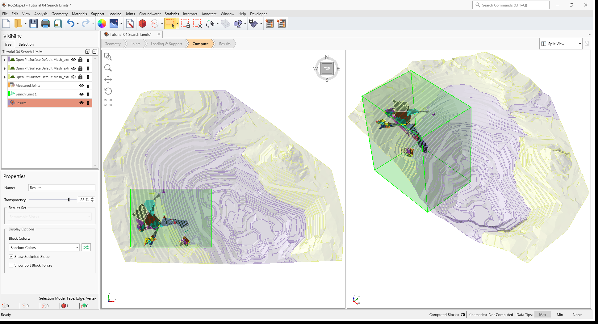
7.0 Compute (with Completely Inside Box Search Limit)
Now let's compute unit blocks with the user-defined Box Search Limit.
7.1 Compute Blocks
- Ensure you are still in the Compute workflow tab
- Select Analysis > Compute Blocks
Only unit blocks fully contained in Search Limit 1 are being considered.
8.0 Add Search Limit By Arbitrary Volume
If we wanted to exclude a sub region contained inside Search Limit 1, we can add another Search Limit which overlaps a portion of Search Limit 1. For example, if we wanted to compute blocks in the southwest region, but excluding anything in the Schist material region of the open pit:
- Select the External piece with Applied Property = Schist from the Visibility Tree (i.e., Open Pit Surface.Default.Mesh_extruded_1).
- Select Analysis > Search Limits > Add Search Limits by Arbitrary Volume
- In the Slope Limit By Entity dialog:
- Set Name = Search Limits 2.
- Set Search Limit Type = Completely Outside.
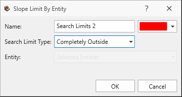
Slope Limit by Entity dialog - Click OK to add the Search Limit.
Search Limits 2 has been added to the model.
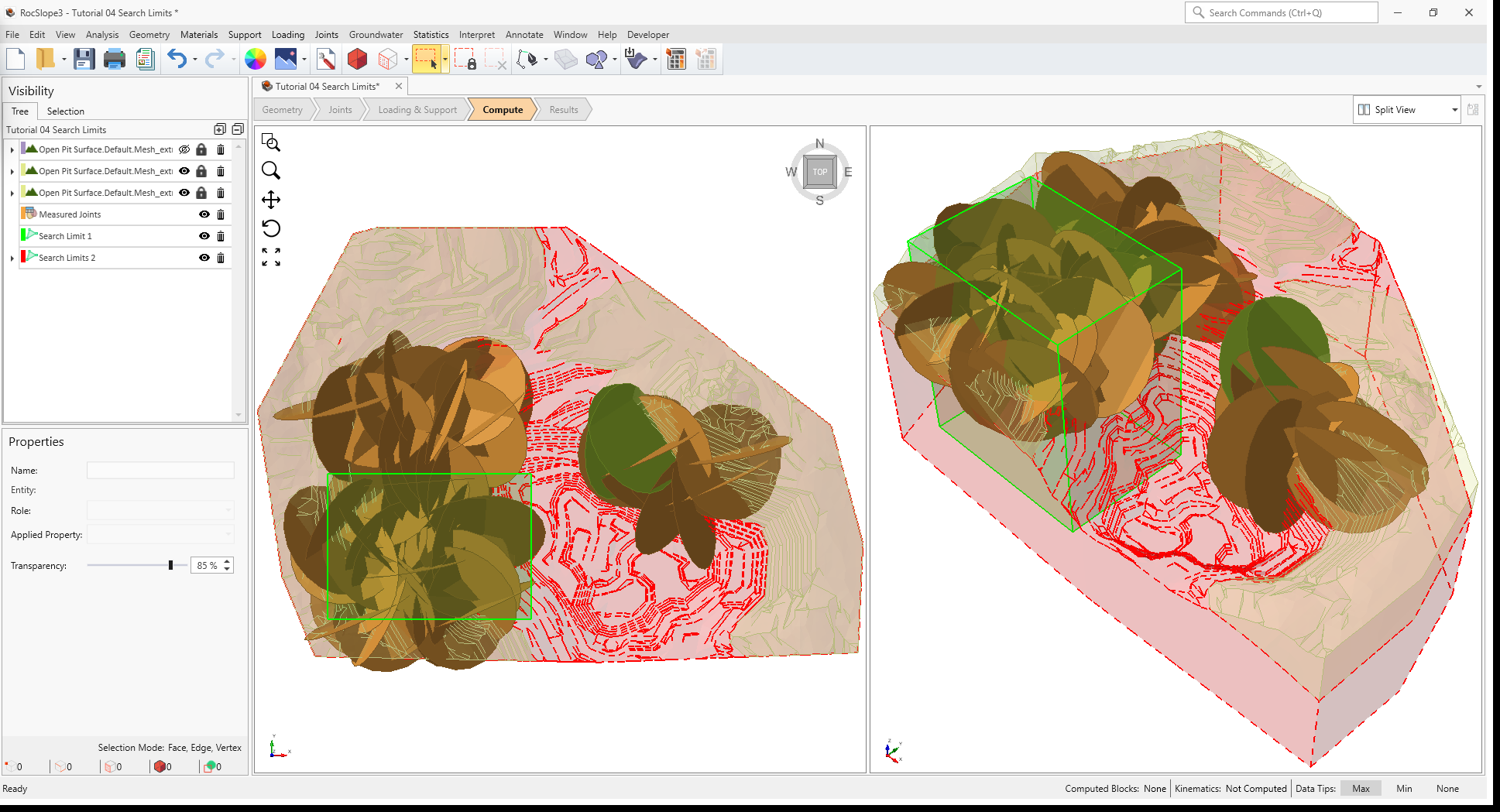
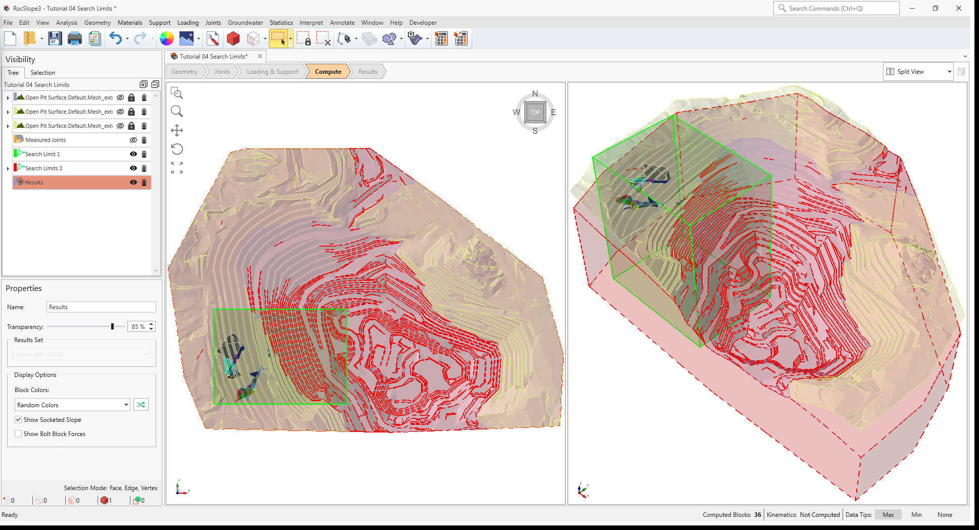
9.0 Compute Blocks (with Arbitrary Volume Search Limit)
Now let's compute unit blocks with the user-defined Arbitrary Volume Search Limit.
- Ensure you are still in the Compute workflow tab
- Select Analysis > Compute Blocks
Only unit blocks which are inside Search Limit 1 but outside Search Limits 2 are being considered.
This concludes Tutorial 04.