8 - Highway Cut with Ru Water Pressure
1.0 Introduction
In this tutorial, a section of a highway with near vertical rock cuts on both sides and jointing will be analyzed under both Dry and Undrained conditions. The effects of Water Pressure can drastically impact slope stability by lowering the normal forces along the sliding joints of blocks, thereby lowering the shear resistance and factor of safety.
Finished Product
The finished product of this tutorial can be found in the Tutorial 08 Highway Cut with Ru Water Pressure folder. All tutorial files installed with RocSlope3 can be accessed by selecting File > Recent Folders > Tutorials Folder from the RocSlope3 main menu.
2.0 Opening the Starting File
- Select File > Recent > Tutorials Folder.
- Go to the Tutorial 08 Highway Cut with Ru Water Pressure folder and open the file Tutorial 08 Highway Cut - dry.rocslope_model.
This model already has the following defined and provides a good starting point to start computing blocks:
- Units
- External geometry
- Material Properties
- Synthetic Joints
- Joint Properties
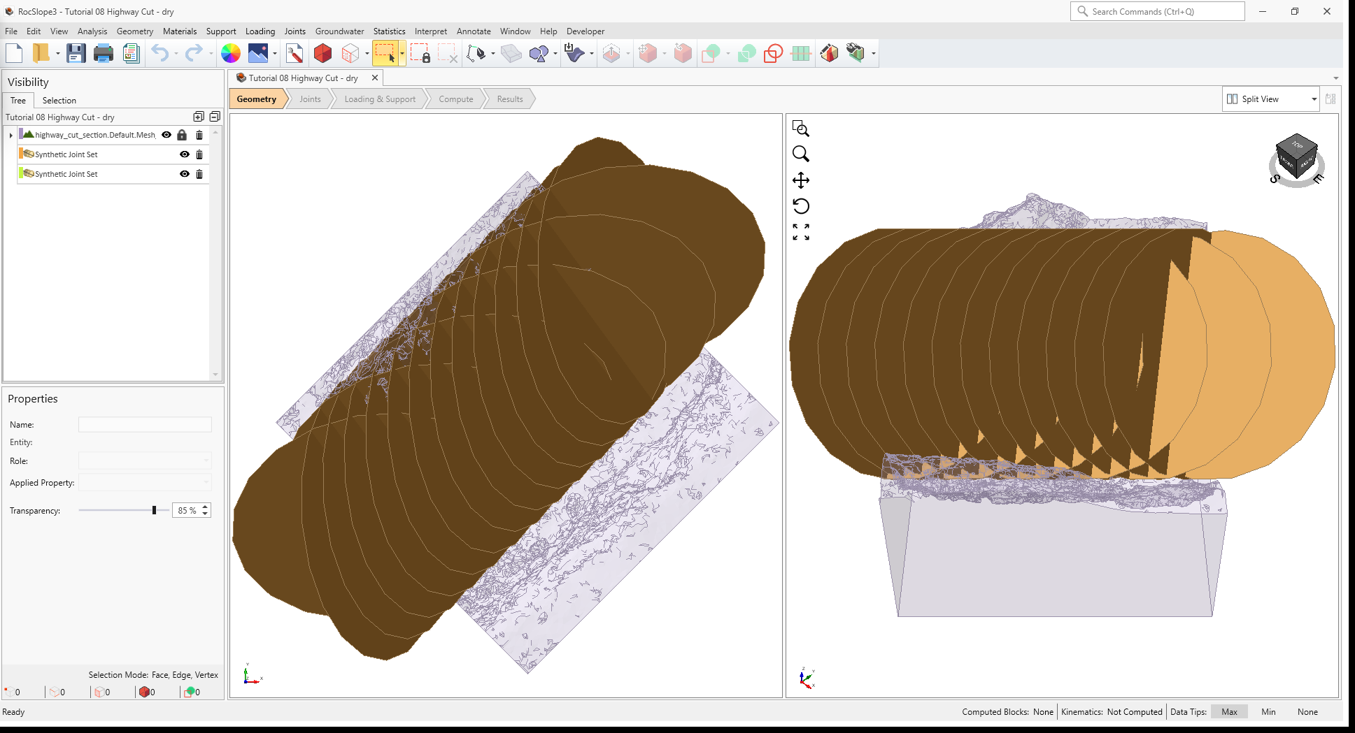
In the starting model, the external is defined by a section of a highway with steep, near-vertical rock slopes straddling both sides of the road.
2.1 Project Settings
Review the Project Settings.
- Select Analysis > Project Settings

- Select the Units tab. Units are Metric, stress as
MPa.
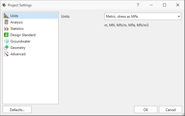
Units tab in Project Settings dialog - Select the Analysis tab.
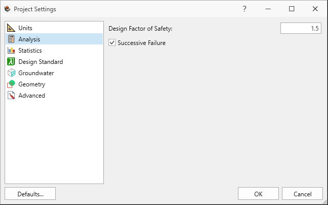
Analysis tab in Project Settings dialog - Design Factor of Safety = 1.5.
- Successive Failure is ON.
- Combined blocks is OFF.
- Click Cancel to exit the dialog.
2.2 Material Properties
Review the Material Properties.
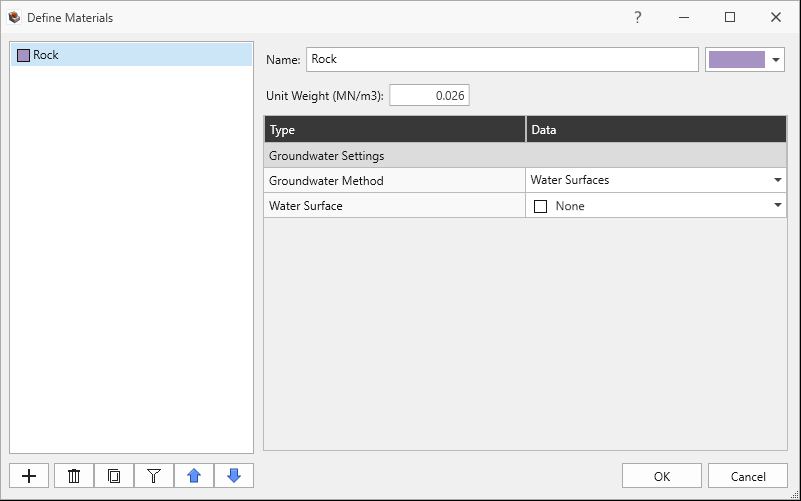
- Select Materials > Define Materials

- One (1) material property is defined in the Define Materials dialog. The Rock material property has:
- Unit Weight = 0.026 MN/m3.
- No Water Surface applied.
2.3 External Geometry
The External is of a highway section with vertical slope cuts on either side and composed of a single volume assigned with the Rock material property.
2.4 Joint Properties
Review the Joint Properties.
- Select Joints > Define Joint Properties

- One (1) joint property is defined in the Define Joint Properties dialog. The Shear
joint property has:
- Strength Type = Barton-Bandis
- JRC = 10
- JCS = 30 MPa
- Phir = 25 degrees
- Waviness = 0 degrees
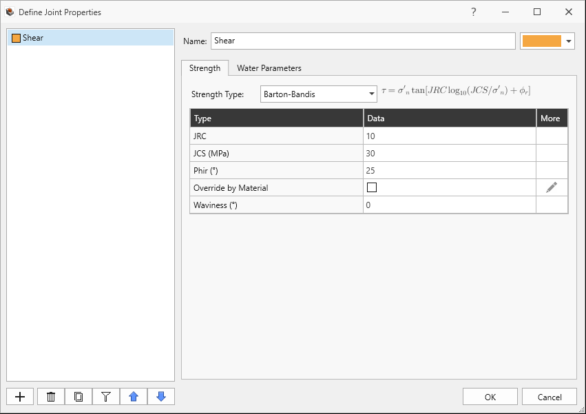
Shear Joint Property Strength tab in Define Joint Properties dialog - Water Pressure Method = Dry
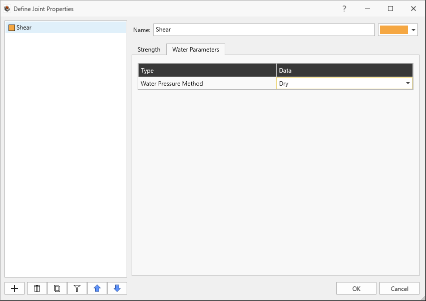
Shear Joint Property Water Parameters tab in Define Joint Properties dialog
- Click Cancel to exit the dialog.
2.5 Synthetic Joints
Review the Synthetic Joint Properties.
- Select Joints > Define Synthetic Joints
 . Two (2) synthetic joint
properties are defined.
. Two (2) synthetic joint
properties are defined. - The Set 1 synthetic joint property has:
- Joint Property = Shear
- Joint Orientation Definition Method = Dip/Dip Direction
- Mean Dip = 60 degrees
- Mean Dip Direction = 85 degrees
- Mean Radius = 12 m
- Mean Spacing = 1.7 m
- Spacing Option = True Spacing.
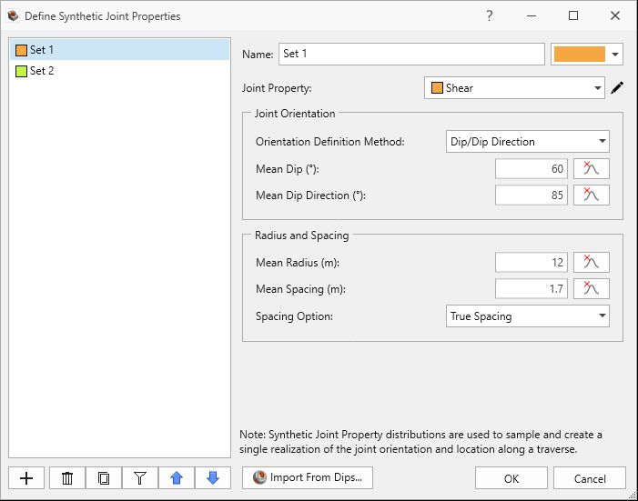
Set 1 Synthetic Joint Property in Define Synthetic Joint Properties dialog
- The Set 2 synthetic joint property has:
- Joint Property = Shear
- Joint Orientation Definition Method = Dip/Dip Direction
- Mean Dip = 45 degrees
- Mean Dip Direction = 170 degrees
- Mean Radius = 12 m
- Mean Spacing = 2.4 m
- Spacing Option = True Spacing.
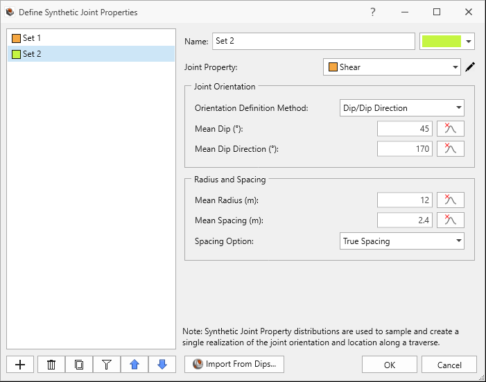
Set 2 Synthetic Joint Property in Define Synthetic Joint Properties dialog
Both Synthetic Joint Sets traverse (data collected over a scanline) from:
- X = 13, Y = 15, Z = 1012 to
- X = -8, Y = -6, Z = 1012
First, we will compute assuming no water pressure effects (i.e., dry).
3.0 Compute (Dry)
RocSlope3 has a two-part compute process.
3.1 Compute Blocks
The first step is to compute the unit blocks which may potentially be formed by the intersection of joints with other joints and the intersection of joints with the free surface.
To compute the unit blocks:
- Navigate to the Compute workflow tab

- Select Analysis > Compute Blocks

As compute is run, the progress bar reports the compute status. Once compute is finished, the Results node is added to the Visibility Tree and All Valid Unit Blocks are blocks are shown in the viewport. The Results node consists of the collection of valid unit blocks and the socketed slope. The original External and Joint Surface visibility is turned off.
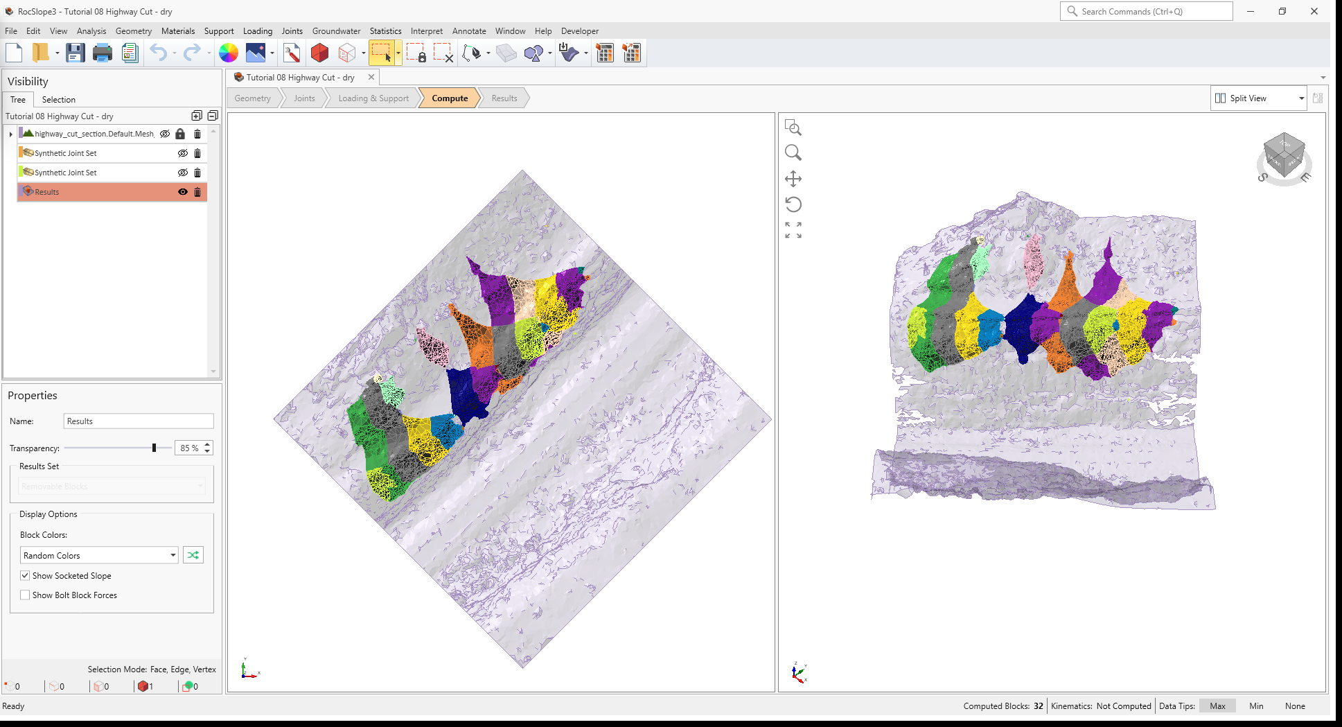
Once compute is finished, the unit blocks are coloured according to the Block Color option (Random
Colors) set in the Results node's Property pane.
Compute Blocks only determines the geometry of the unit blocks. In order to obtain other information such as the factor of safety, Compute Kinematics needs to be run.
3.2 Compute Kinematics
The second and final compute step is to compute the removability, forces, and factor of safety for each of the valid unit blocks.
To compute the block kinematics:
- Ensure that the Compute workflow tab is the active workflow.
- Select Analysis > Compute Kinematics

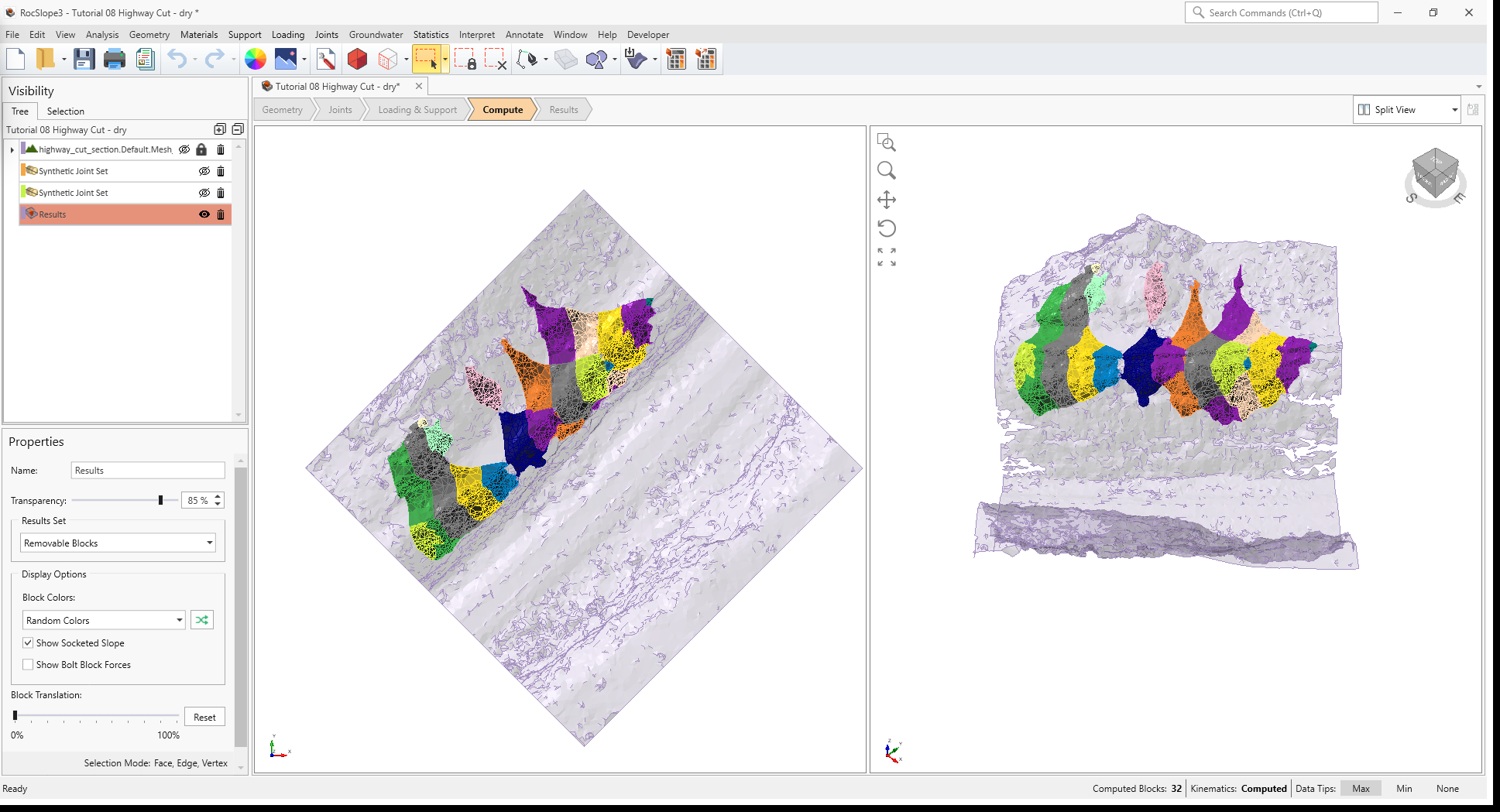
As compute is run, the progress bar reports the compute status. By default, after Compute Kinematics is run, only Removable Unit Blocks are shown.
4.0 Interpreting Results
Once both blocks and kinematics are computed, check to see if any unit blocks have failed (i.e., Factor of Safety < Design Factor of Safety = 1.5).
- Navigate to the Results workflow tab

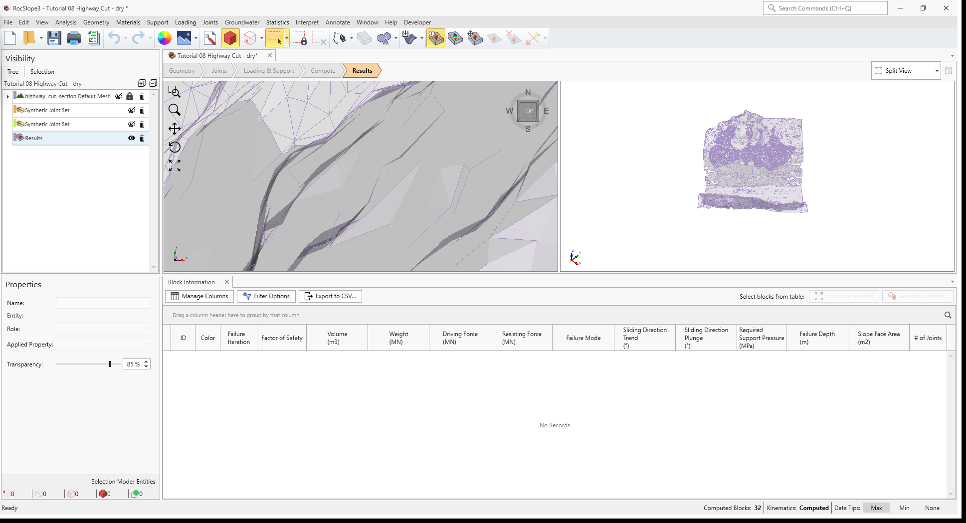
- Select Interpret > Block Information

- Select the Results node from the Visibility Tree.
- In the Results node Properties pane, set the Block Type = Unit Blocks and Results Set = Failed Unit Blocks (FS < Design FS).
Visualizing blocks can be difficult when the slope extents are large compared to the block extents.
To zoom into all blocks:
- Select Interpret > Zoom To All Blocks

No blocks have failed.
5.0 Ru Water Pressure
Now, let's consider the effects of water pressure in the joints. For this example, the Ru
Coefficient Groundwater Method will be used which computes water pressure as a fraction (i.e., Ru
Coefficient) of the vertical earth pressure.
To apply Ru coefficient for modeling groundwater:
- Select Materials > Define Materials
- In the Define Materials dialog, for the Rock material property:
- Set Groundwater Method = Ru Coefficient
- Set the Ru Value = 0.4
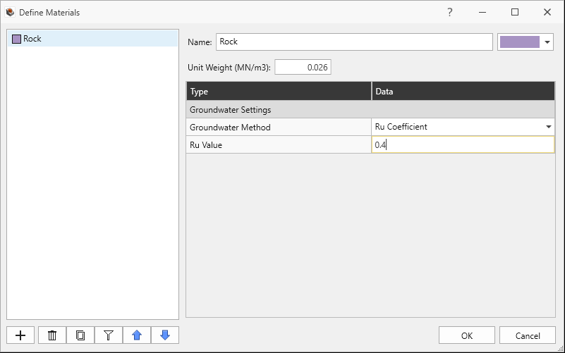
Rock Material Property with Ru Coefficient Groundwater Method set in Define Materials dialog - Click OK to save the material property and exit the dialog.
Next, we have to set the applied Joint Property to use the Groundwater conditions set by the Material Property:
- Select Joints > Define Joint Properties
- In the Define Joint Properties dialog, for Shear joint property:
- Navigate to the Water Parameters tab.
- Set Water Pressure Method = Material Dependent. Any joints with this applied joint
property will have water pressure dictated by the Groundwater Method in any portion of the material it
passes.
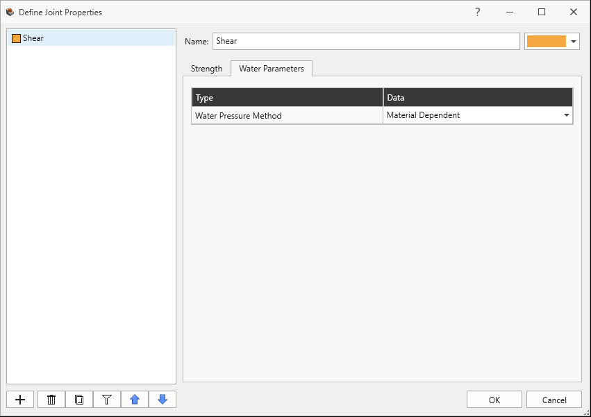
Shear Joint Property with Material Dependent Water Pressure method set in Define Joint Properties dialog - Click OK to close the dialog.
6.0 Compute (Ru Water Pressure)
Recompute unit blocks and kinematics.
- Ensure that the Compute workflow tab is the active workflow.
- Select Analysis > Compute Blocks . Computation of blocks are unaffected by
water.
- Select Analysis > Compute Kinematics
7.0 Interpreting Results
Once both unit blocks and kinematics are computed, check to see if any unit blocks have failed (i.e., Factor of Safety < Design Factor of Safety = 1.5).
- Navigate to the Results workflow tab
- Select Interpret > Block Information
- Select the Results node from the Visibility Tree.
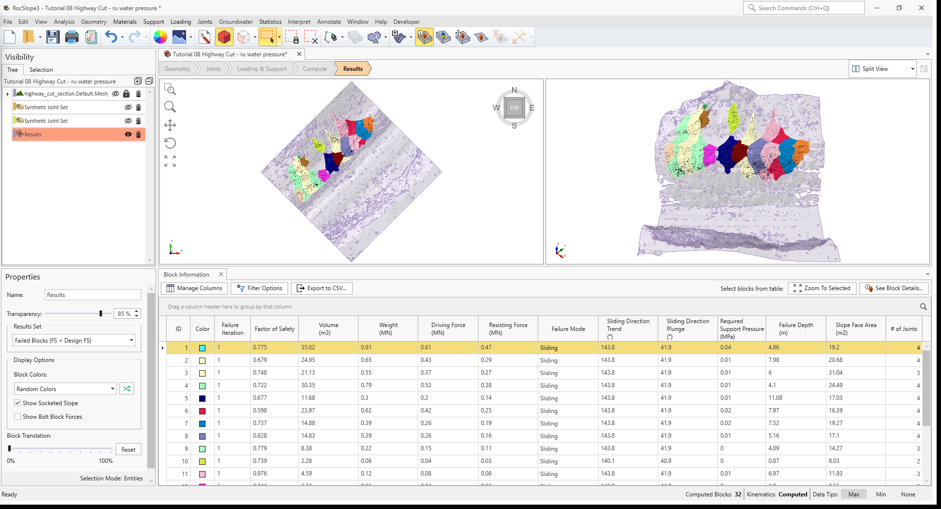
- In the Results node Properties pane, set the Results Set = Failed Unit Blocks (FS < Design FS).
Visualizing blocks can be difficult when the slope extents are large compared to the block extents.
To zoom into all blocks:
- Select Interpret > Zoom To All Blocks.
All unit blocks have failed. Failure Modes for all unit blocks is Sliding since the water pressure has caused the reduction of effective normal stresses acting along sliding joints. When this happens, shear resistance is reduced and the Factors of Safety are also reduced.
This concludes Tutorial 08.