9 - Kinematic Analysis (Planar Sliding)
1.0 Introduction
Based on kinematic considerations and frictional properties of joint planes, it is possible to perform stability analyses such as toppling, Planar Sliding and Wedge Sliding on a stereonet. This tutorial demonstrates how to perform stability analyses under Planar Sliding failure mode using the Kinematic Analysis option in Dips.
The tutorial is a continuation from Tutorial 07 - Feature Analysis (which uses the example file Examppit.dips8) . The data has been collected by a geologist working on a single rock face above the first bench in a young open pit mine.
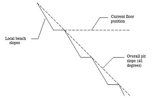
The rock face above the current floor of the existing pit has a dip of 45 degrees and a dip direction of 135 degrees. The current plan is to extend the pit down at an overall angle of 45 degrees. This will require a steepening of the local bench slopes, as indicated in the figure above. The local benches are to be separated by an up-dip distance of 16m. The bench roadways are 4m wide.
Topics Covered in this Tutorial:
- Kinematic Analysis of Planar Sliding Failure Mode
- Friction Cones
- Daylight Envelope
Finished Product:
The finished product of this tutorial can be found in the Tutorial 09 Kinematic Analysis (Planar Sliding).dips8 file, located in the Examples > Tutorials folder in your Dips installation folder.
2.0 Model
If you have not already done so, run Dips by double-clicking on the Dips icon in your installation folder. Or from the Start menu, select Programs > Rocscience > Dips > Dips.
If the Dips application window is not already maximized, maximize it now, so that the full screen is available for viewing the model.
To save us some time, this tutorial will use the Tutorial 07 Feature Analysis.dips8 file which already has the required pit slope plane (User Plane) and .
- Select File > Recent Folders > Tutorials Folder
 from the menu.
 - Open the Tutorial 07 Feature Analysis.dips8 file. Save this example file with a new file name without overwriting the original file.
- Select File > Save As
 from the menu.
 - Enter the file name Tutorial 09 Kinematic Analysis (Planar Sliding) and Save the file.
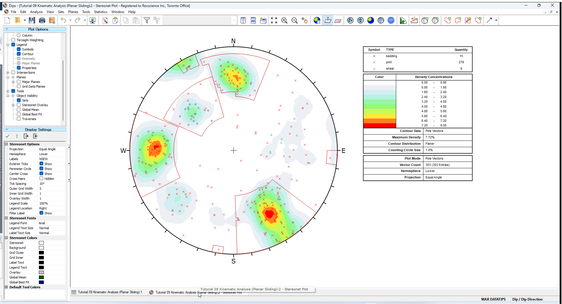
You should see the Stereonet Plot View shown in the following figure.
If you do not see the plot below, then use the Sidebar Plot Options to view pole vectors and contours on the stereonet.
3.0 Planar Sliding (No Lateral Limits)
We will now proceed with the analysis of 1 of 3 potential failure modes of interest: Planar Sliding.
- Select the Kinematic Analysis
 option from the Analysis menu.
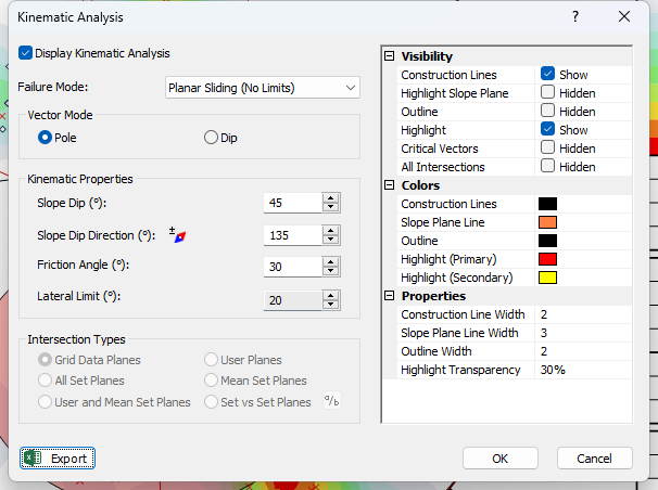
 - In the Kinematic Analysis dialog:
- Select the Display Kinematic Analysis checkbox.
- Select Failure Mode = Planar Sliding (No Limits) from the dropdown.
- Enter Slope Dip = 45 degrees.
- Enter Slope Dip Direction = 135 degrees .
- Enter Friction Angle = 30 degrees.
- Select OK.
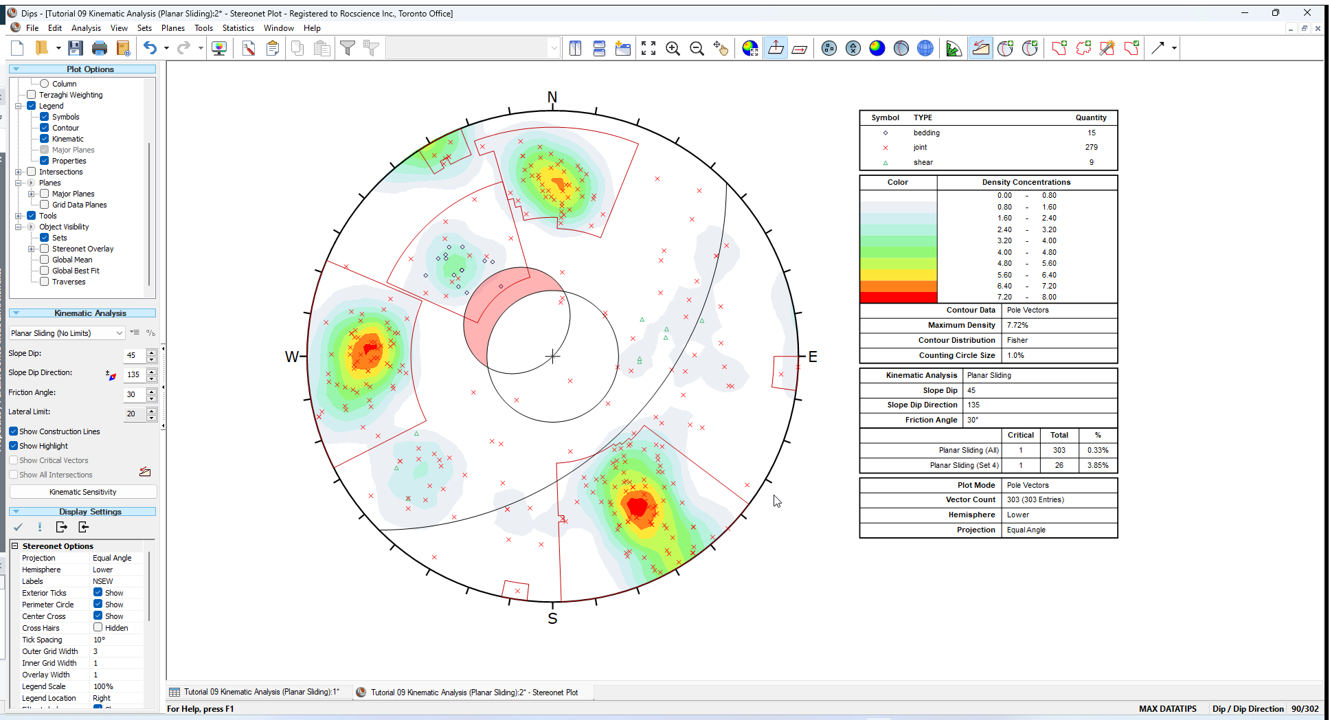
You should see the Kinematic Analysis overlay for Planar Sliding as shown below.
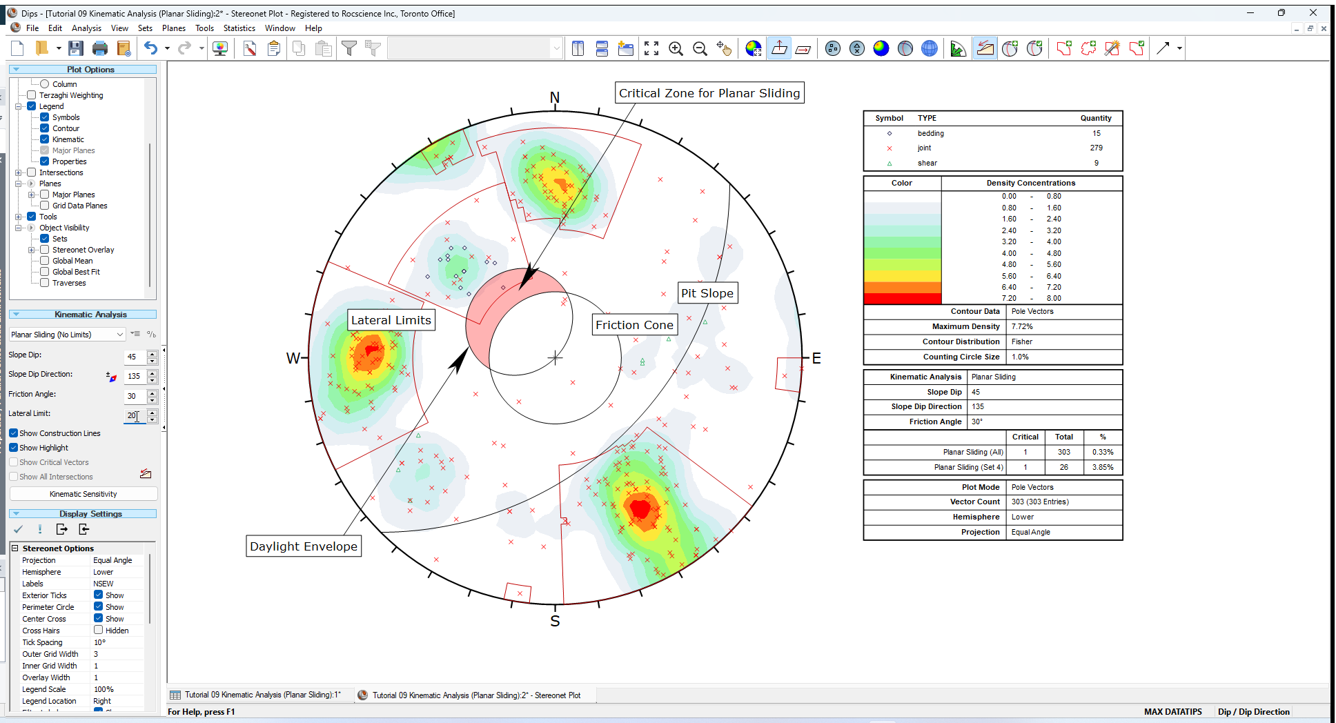
The key elements of Planar Sliding using pole vectors are:
- Slope Plane and Daylight Envelope
- Pole Friction Cone (angle measured from center of stereonet)
- Lateral Limits (optional)
These are discussed below.
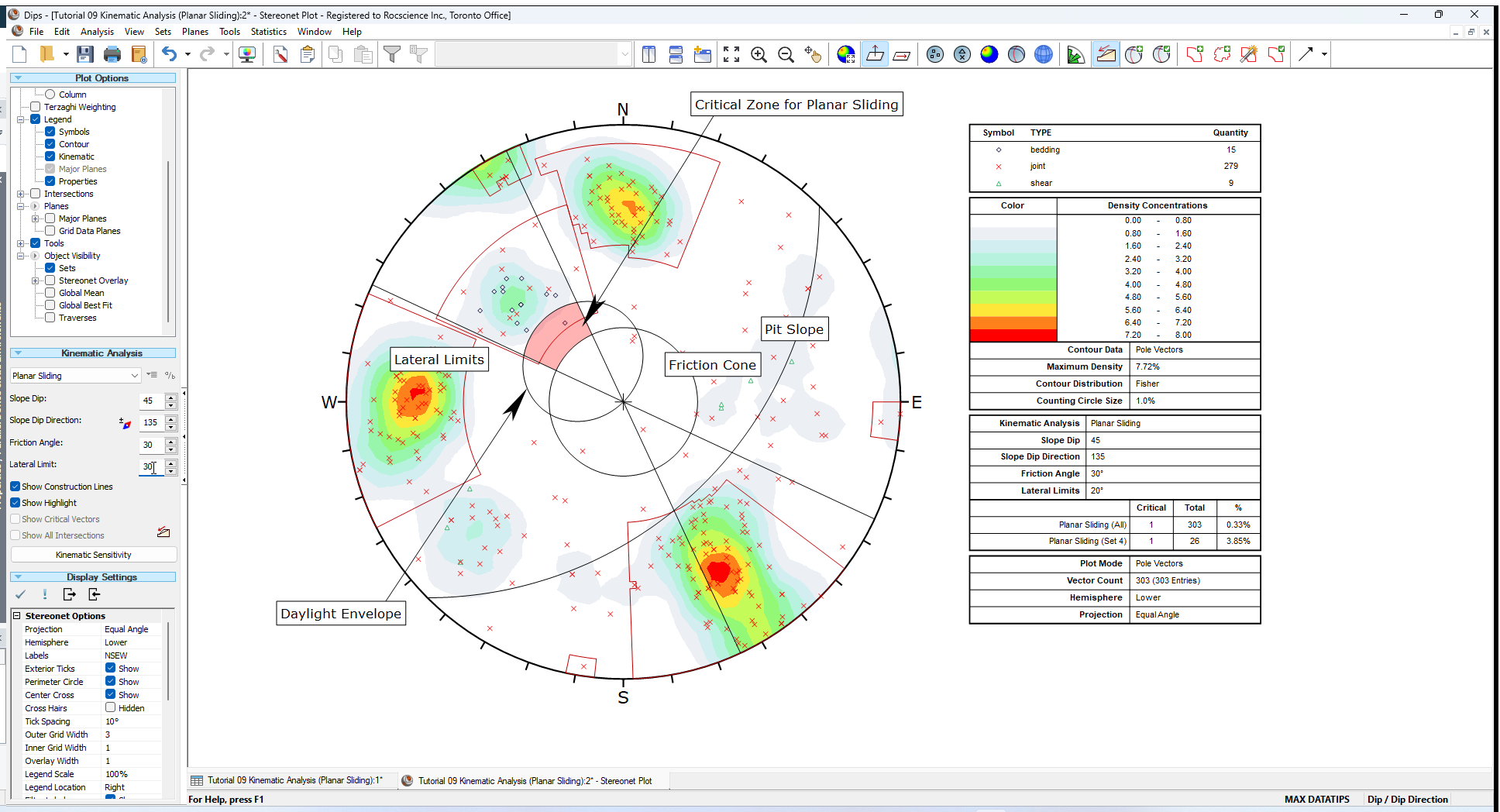
NOTE: The text labels in the figure were manually added using the Add Text  option in the Tools menu.
3.1 SLOPE PLANE
The great circle of the slope plane is displayed and labeled Pit Slope on the above figure with orientation Dip / Dip Direction = 45 / 135.
NOTE:
- The slope plane is automatically displayed by the Kinematic Analysis when Construction Lines or the Highlight Slope Plane option is selected.
- The slope plane that we added using the Add User Plane
 option is now hidden.
3.2 DECLINATION CORRECTION FOR SLOPE DIRECTION
Beside the edit box for entering the Slope Dip Direction, you will notice a small Declination Correction  button, which allows you to apply the Declination Correction (entered in Project Settings) to the value entered for Slope Dip Direction.
For this example, we will assume that the corrected value has already been entered, so we will not apply this option.
3.3 DAYLIGHT ENVELOPE
The Daylight Envelope corresponding to the slope plane is required for a Planar Sliding Kinematic Analysis as shown in the above figure. A Daylight Envelope allows us to test for kinematics (i.e., a rock slab must have somewhere to slide into – free space). Any pole falling within this envelope is kinematically free to slide if frictionally unstable.
3.4 FRICTION CONE
A pole friction cone of 30 degrees is displayed. Any pole falling outside of this cone represents a plane which could slide if kinematically possible.
3.5 CRITICAL ZONE FOR PLANAR SLIDING
The crescent shaped zone formed by the Daylight Envelope and the pole friction circle encloses the region of Planar Sliding. Any poles in this region represent planes which can and will slide (i.e., the critical zone for planar failure is defined by poles), which are:
- OUTSIDE of the pole friction circle, and
- INSIDE the daylight envelope
This region is automatically highlighted for Planar Sliding analysis as shown in the above figure. The highlight colour and other display options can be customized in the Kinematic Analysis dialog.
4.0 Results Legend
A summary of the Planar Sliding Kinematic Analysis results is displayed in the Legend.
In this case only a single pole is contained within the critical Planar Sliding zone. The Legend provides results as a percentage of all poles in the file (1/303), and as a percentage of poles for individual sets (1/26 for Set number 4).
In either case, you can see that the probability of Planar Sliding is very low for this combination of slope orientation and friction angle.
5.0 Planar Sliding
The Planar Sliding analysis described above considers the entire daylight envelope as a kinematically valid sliding zone.
5.1 LATERAL LIMITS
In practice it has been observed that Planar Sliding (and toppling) tends to occur when the dip direction of planes is within a certain angular range of the slope dip direction. Typically a range of plus/minus 20 or 30 degrees is considered, and poles outside of this range represent a low risk.
To add lateral limits to the Kinematic Analysis, return to the Kinematic Analysis dialog and change the failure mode to Planar Sliding. Or alternatively:
- Set Failure Mode = Planar Sliding from the Sidebar Kinemetic Analysis (instead of Planar Sliding (No Limits)).
- Enter Lateral Limit = 30 degrees.
You should see the following.
The lateral limits are simply two straight lines which define an angular range measured from the dip direction of the slope. In this case we have used the default value of plus/minus 20 degrees.
For this example, the addition of lateral limits does not change the results, since only a single pole is in the critical Planar Sliding zone. However this depends on your file, and the inclusion of lateral limits could significantly change results if there are many poles inside the daylight envelope.
5.2 PLANAR SLIDING RELEASE PLANES
An important assumption regarding “pure” Planar Sliding is that release planes are assumed to exist (e.g. lateral joints, tension cracks or other mechanism) which allow a Planar Sliding failure to occur.
Such release planes are not explicitly modeled in the Planar Sliding Kinematic Analysis but you should be aware that some release mechanism must exist to allow a block sliding on one plane to be removed from the slope. Planar Sliding can be considered a special case of Wedge Sliding where sliding takes place on only one plane, and other planes act as release planes.
6.0 Summary
Kinematic Analysis of rock slope failure modes using stereonets is an extremely useful and easy to understand analysis tool which allows you to quickly evaluate potential failure modes. However keep in mind the following.
- The analyses presented here are just a starting point for more detailed analysis and should always be accompanied by a more thorough field analysis in cases where a risk of failure is indicated.
- Real slopes may exhibit more than one failure mode. It is rare to see pure examples of these failure modes, particularly with the toppling analysis, which may exhibit complex behaviours involving sliding, toppling, rotating etc.
- Even if a Kinematic Analysis indicates risk of failure, this does not necessarily mean that failure will occur, since factors other than kinematics and friction angle may work to increase stability (e.g. joint cohesion, joint persistence etc). Conversely, other factors may decrease stability (e.g. water pressure) of kinematically safe slopes.
- It is important to look beyond statistical results (e.g. mean set plane orientations) and consider major discrete structures such as shear zones which may have a dominant effect on stability due to low friction angles and inherent persistence.
- More detailed analysis including safety factor calculation can be carried out with the Rocscience programs SWedge (wedge analysis), RocPlane (planar analysis) and RocTopple (toppling analysis).
7.0 References
- Goodman, R.E. 1980. Introduction to Rock Mechanics (Chapter 8), Toronto: John Wiley, pp 254-287.
- Hudson, J.A. and Harrison, J.P. 1997. Engineering Rock Mechanics – An Introduction to the Principles, Pergamon Press.
This completes the tutorial. You are now ready for the next tutorial, Tutorial 10 - Kinematic Analysis (Wedge Sliding) in Dips.