5 - Laser Scanner Data Import
1.0 Introduction
In this tutorial, you will become familiar with the process of importing a laser scanner dataset to reconstruct and generate a 3D model in ShapeMetriX’s ModelEditor tool.
The ModelEditor is a convenient tool for:
- Generating 3D models from existing *.e57 laser scanner or *.obj datasets
- Converting models from previous ShapeMetriX versions in the *.jm3 file format to the new ShapeMetriX v5.0 compatible *.jm3x file format
- Editing existing 3D models by trimming and confining it to the area of interest
Topics Covered in this Tutorial
- Laser Scanner Data Import
- 3D Model Reconstruction and Saving
Project Files and Finished Product
The finished product of this tutorial, as well as all project materials can be found Tutorial 5 – Laser Scanner Data.zip.
2.0 Importing a Laser Scanner Dataset
If you have not already done so, run the ShapeMetriX (SMX) program by double-clicking the ShapeMetriX  icon on the desktop or in your installation folder, or by selecting Programs > ShapeMetriX in the Windows Start menu.
When the program starts:
- Select ModelEditor
 to run the ModelEditor tool.
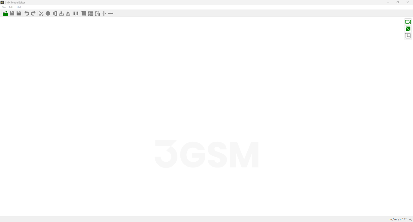
Whenever the ModelEditor tool runs, a default blank work page opens as shown in the image below.
This tutorial will use an example Open Pit Mine dataset to demonstrate the laser scanner import feature. The openpitmine.e57 file (© Copyright 2011, Riegl LMS GmbH) can be found in the downloaded Tutorial 5 – Model Files > Input Files folder.
To import the Laser Scanner data:
- Select File > Import 3D Model > Import from E57.
- Select openpitmine.e57 in the downloaded folder.
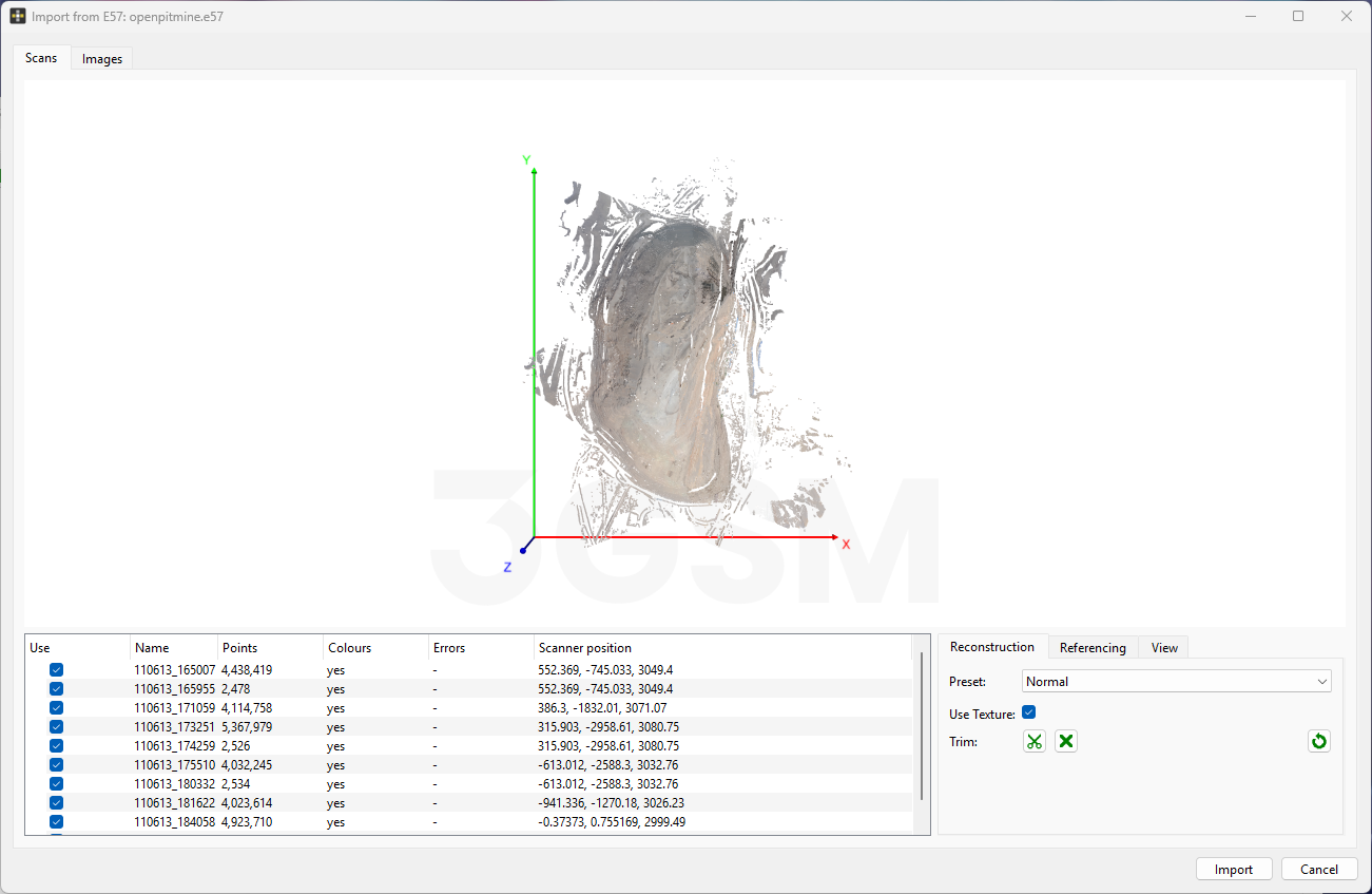
- The Import from E57 dialog will open and the laser scanner dataset will be imported.
The list of imported scans is presented at the bottom of the Scans tab, indicating the name and the number of points for each scan, if any associated colour data is included in the scan, and the scanner’s position in space.
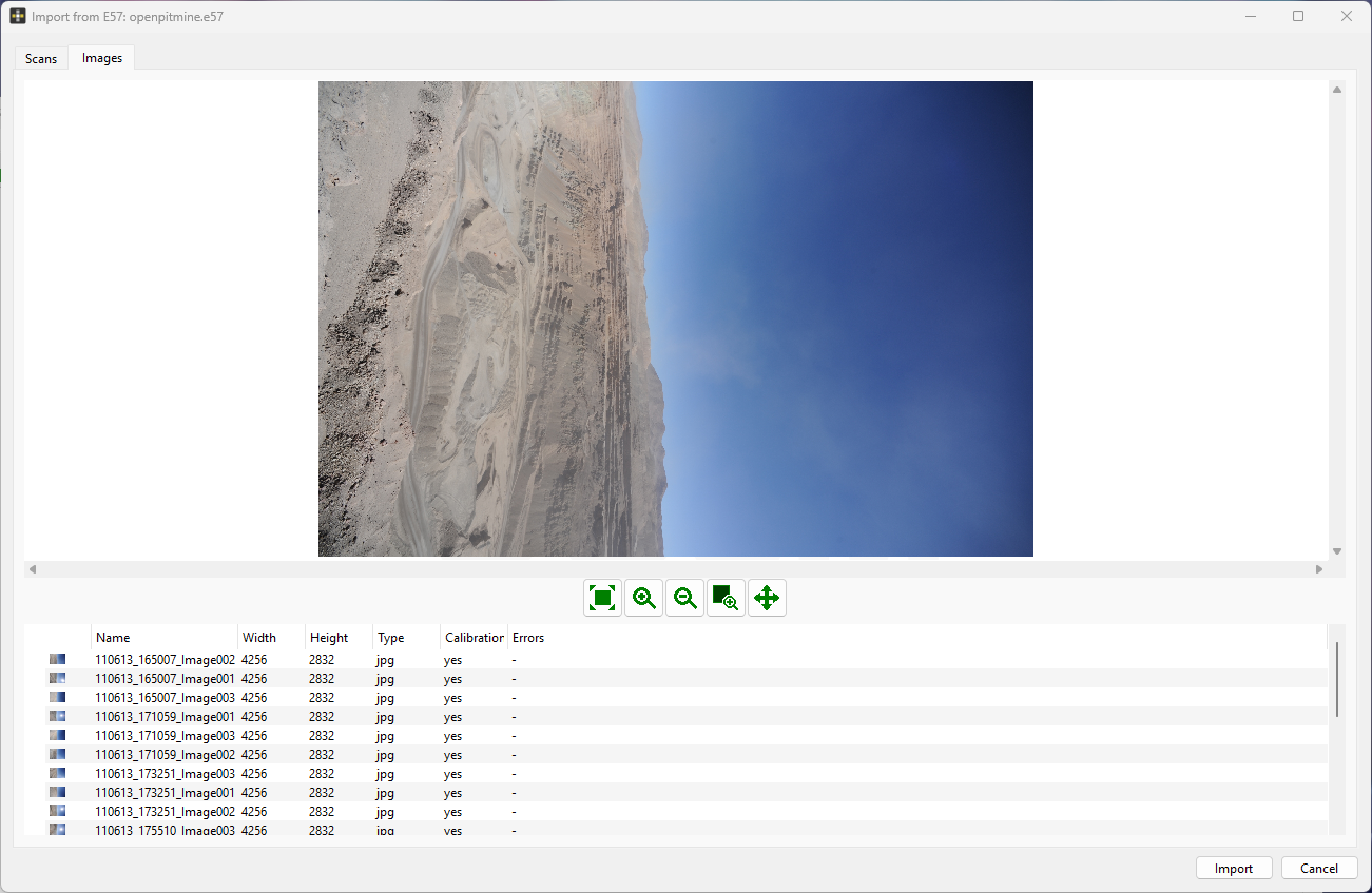
Any images associated with the scan data are also imported under Images tab. Select the Images tab and review the images (texture information) provided with the import.
3.0 3D Model Generation
The Import from E57 dialog requires Reconstruction and Referencing inputs to run the reconstruction and generate a 3D model.
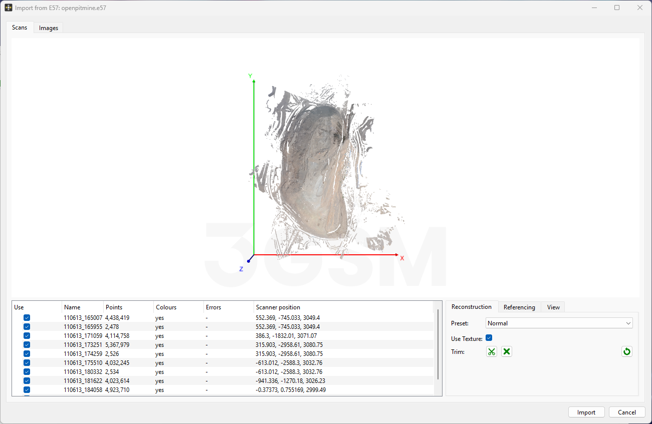
The Reconstruction tab (in the Scans tab) includes the following inputs:
- Preset: to define the resolution of detailed object geometry including a detailed point cloud, surface mesh and the texture projected onto the 3D model (if colour data and/or images are available with the scan). There are three presets available:
- Fast dense construction preset generates low resolution topography and low-resolution texture (can be used for volume calculations, etc.).
- Normal dense construction preset is the default preset option and generates medium resolution topography and high-resolution texture (can be used for blast design, single faces and benches for rock mass characterization, etc.).
- High dense construction preset generates high resolution topography and high-resolution texture (can be used for rock mass characterization, etc.).
- Use Texture: to enable/disable the texture projected onto 3D model, if colour data and/or images are available with the scan.
- Trim: to trim the point cloud in the 3D viewer.
If there is no colour data and/or images available, the Use Texture and Texture Quality features will be inactive, and the 3D model will be generated without texture information.
Tip: The imported point cloud, extension of the point cloud and the scanner positions can be hidden/shown using the Point Cloud, Bounding Box and Scanner Positions checkboxes in the Scans > View tab. The size of the displayed scanners can also be adjusted by using the Scanner View Size slider in the View tab.
The Referencing tab includes the following inputs:
- Referencing: to choose the referencing mode.
- Coordinate system: to select the coordinate system if a specific coordinate system is to be used.
3.1 Reconstruction
- Set the following inputs in Reconstruction tab:
- Preset = Normal
- Use Texture = ON
3.2 Referencing
- Set the following inputs in Referencing tab:
- Referencing = Referenced (generic E, N, H)
Co-ordinate system = Generic, Meter [m]
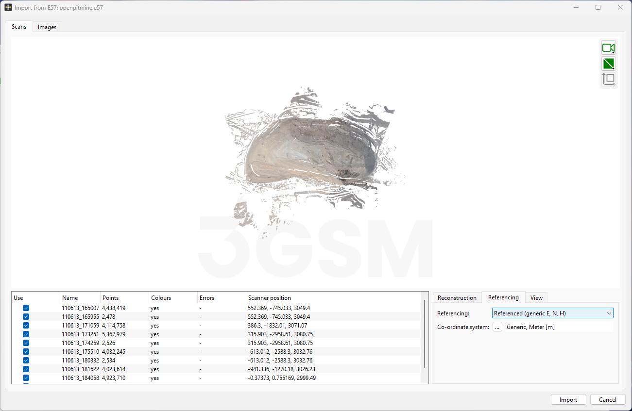
Entered inputs in Referencing tab
- Click Import to confirm the inputs and choose the directory on your computer to save the 3D model .jm3x file.
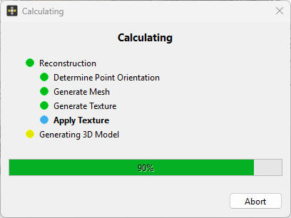
The progress window will appear and reveal the status of the 3D model generation including a live display of progress.
4.0 3D Model Output
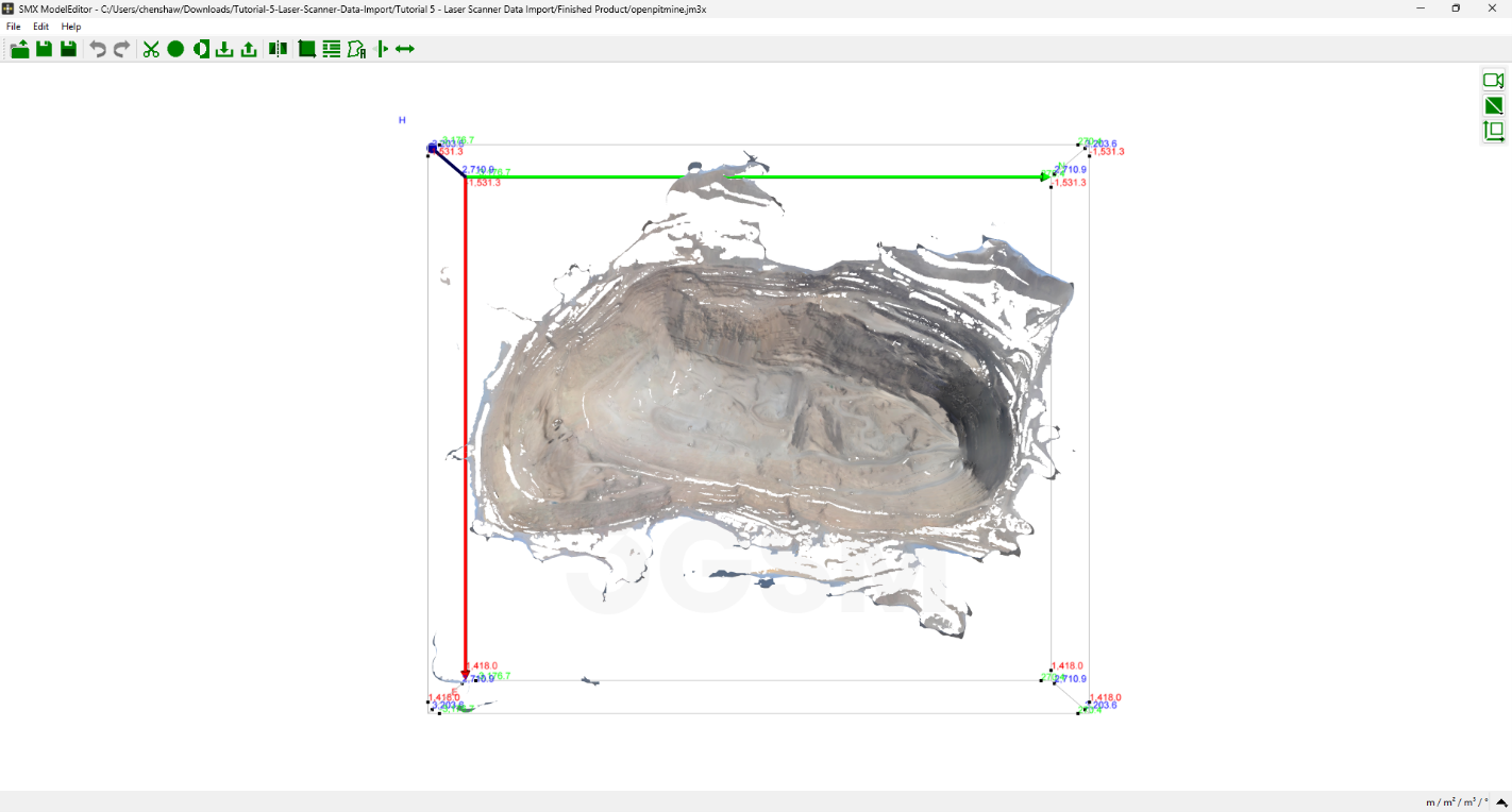
Once the 3D Model Generation process is completed, a 3D model with texture is generated. An output model file (.jm3x) and reconstruction log are automatically saved in the previously selected directory. The resulting 3D model is displayed in the 3D viewer.
Inspect the generated 3D model in 3D Model Viewer and click Close to leave ModelEditor.
This concludes the tutorial for Laser Scanner Data Import.