2 - Standard and Constrained Referencing using Ground Control Points
1.0 Introduction
MultiPhoto is a convenient tool designed for generating 3D models from multiple overlapping images, typically obtained from aerial photography using Unmanned Aerial Vehicle (UAV) systems. After the user sets all the input parameters, the reconstruction process runs automatically. Additionally, MultiPhoto includes standard and constrained referencing features that references the 3D model to a higher-level coordinate system using externally surveyed Ground Control Points (GCP).
This tutorial help will you become familiar with the process of performing standard and constrained referencing in ShapeMetriX’s MultiPhoto tool.
Topics covered in this tutorial
- Standard Referencing
- Constrained Referencing
1.1 Project Files and Finished Product
The finished products of this tutorial and all required project files can be found in Tutorial 2 - Standard and Constrained Referencing Using Ground Control Points.zip.
1.2 Standard and Constrained Referencing
Standard Referencing is a post-processing step which is performed after Dense Reconstruction of the 3D model (3D model generation is discussed in more detail in Tutorial 1 – 3D Model Generation).
MultiPhoto provides three different modes of standard referencing:
- Full Reference 3D model is converted into a higher-level coordinate system using the known coordinates of at least three externally surveyed GCPs through a similarity transformation.
- Single Point 3D model is transferred to a coordinate system using the coordinates of a single externally surveyed point (GCP) through a similarity transformation. This mode is only available if the model is already referenced (EXIF GPS). It allows the 3D model to be transferred to a user-defined coordinate system.
- Sample Mode 3D model is scaled in a local coordinate system.
Constrained Referencing optimizes the 3D model by using the positions of externally surveyed GCPs to achieve better spatial accuracy. Initial camera positions are readjusted and optimized, and the generated 3D points of the dense point cloud (3D model) are aligned to the GCP coordinates.
Constrained Referencing requires a step-by-step procedure for generating the 3D model. First, the image data is loaded in the Configure Project view and coarse 3D point cloud is created using Coarse Reconstruction. Then, in an intermediate step, GCP constrained optimization of the model (Constrained Referencing) is performed. After this optimization, the final 3D model (*.jm3x) is generated using Dense Reconstruction.
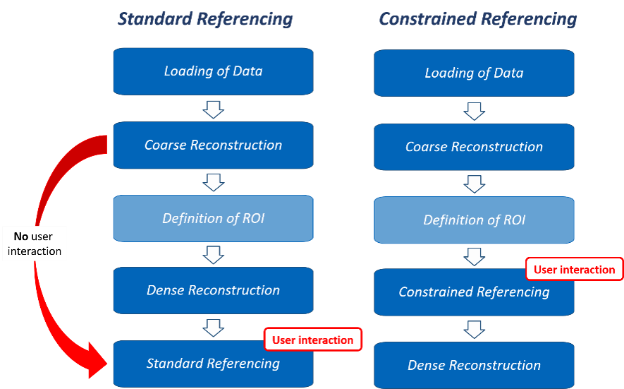
The workflow of Standard Referencing and Constrained Referencing is summarized in the chart below. Please note that definition of a Region of Interest (ROI) is optional and can be skipped.
2.0 Standard Referencing
Standard referencing can be performed in two ways:
- As the last step during a standard 3D model generation procedure (3D model generation is discussed in more detail in Tutorial 1 – 3D Model Generation).
- By selecting Perform Referencing
 in the MultiPhoto Workflow Selection page and loading an existing project file (*.smm file; coarse reconstruction) and corresponding 3D model file (*.jm3x file; dense construction).
2.1 Project Import
- Run the ShapeMetriX (SMX) program by double-clicking the SMX
 icon in your installation folder or by selecting Programs > ShapeMetriX > ShapeMetriX in the Windows Start menu.
ShapeMetriX comes with several example images and files installed with the program. For this tutorial though, we will use the Bench Example.smm, Bench Example.jm3x and GCP.csv files included in the downloaded Tutorial 2 - Standard and Constrained Referencing Using Ground Control Points.zip folder to demonstrate the standard referencing features of ShapeMetriX.
- Select the MultiPhoto
 tool.
tool. - Select Perform Referencing
- Open the Bench Example.smm project file and Bench Example.jm3x 3D model file.
This will open the dense reconstructed 3D model file.
- Select Referencing > Control Points to perform Standard Referencing using Ground Control Points (GCP).
2.2 Referencing
In this example, we will use six externally surveyed GCPs for Standard Referencing to convert the 3D model into a higher-level coordinate system. Hence, we will proceed with Full Reference mode.
To add a GCP:
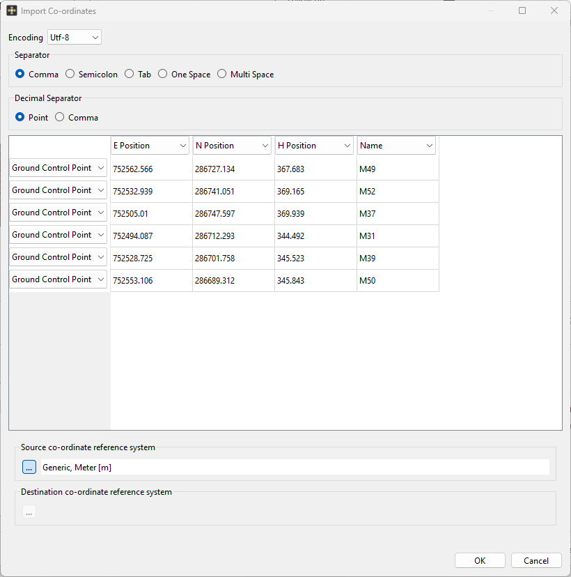
- Click the Load GCP from Text File
 button and open the GCP.csv file.
 - Click the drop down and set row one as E Position (Easting), row two as N Position (Northing), row three as H Position (Elevation), and row four as Name.
- For Source Co-ordinate Reference System, click
 and select Generic, Meter [m].
 - Click OK
Once the GCPs are imported:
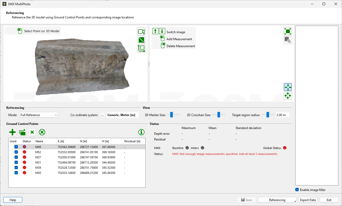
- Select one GCP in the list and localize its position in the 3D viewer by clicking the left mouse button. To help locate the ground control points, scroll the mouse wheel to zoom in and out, and click/hold the mouse wheel to pan the image. When you left-click in the 3D viewer and select the point, the list of reference images will be updated, and the active images including selected GCP will be shown in the viewer.
- Choose the Manual Target Mode
 icon or the Automatic Mode icon and centre the target by clicking with the mouse in the viewer. For locating the target discs the image should be zoomed as much as reasonable for visual interpretation.
 - Choose at least 2 images (more than 3 are recommended) showing the same GCP and centre the target position in the viewer (Tip: you can switch between the individual images in the list by using the left and right arrow keys). The status signals Baseline and the Inliers turn into green, and the error of re-projection and depth is displayed in the GCP list.
- Activate the next GCP in the list and repeat the steps 1 – 3 until all GCP positions are localized.
Your GCP list should look like this.
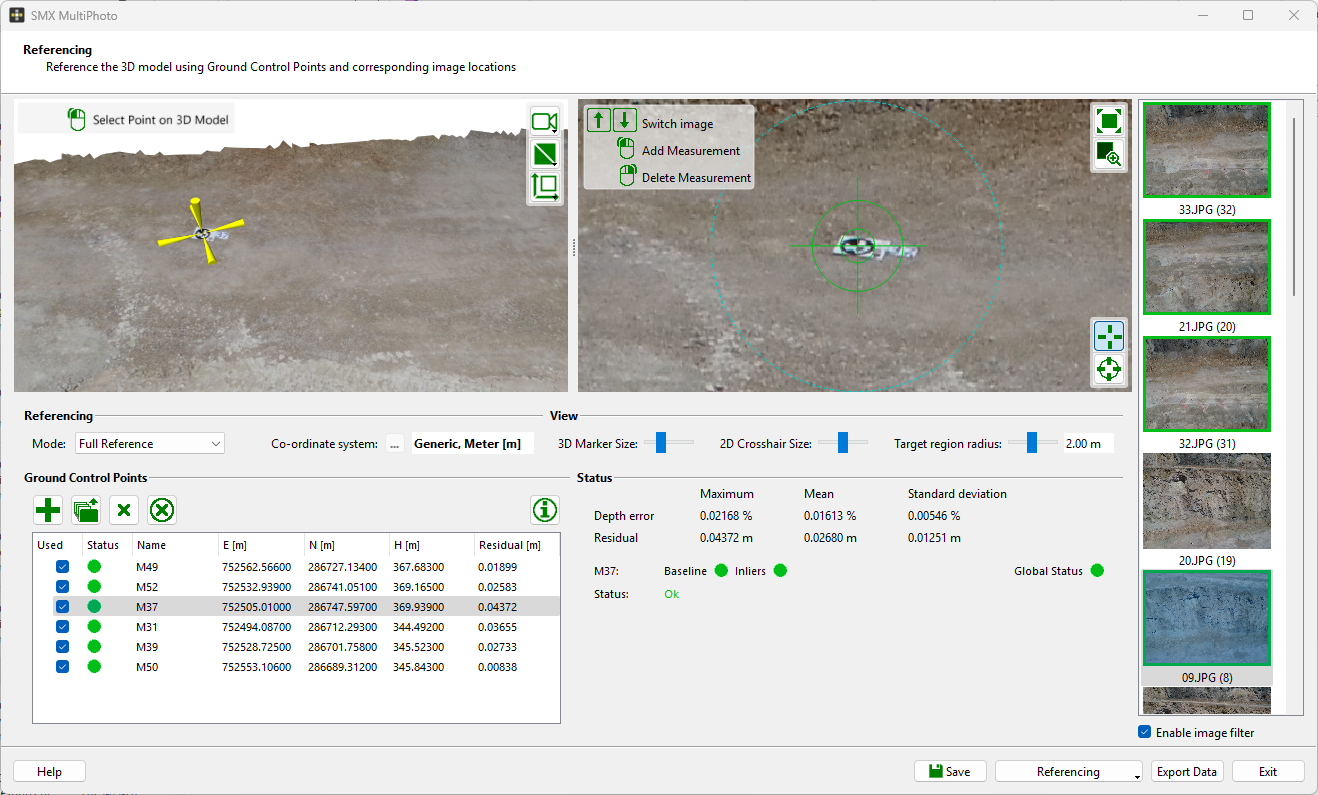
After all the GCP positions are localized the Status Information should be OK, and the Status Signal should be Green. Once you check the status information click Save to save the referenced 3D model.
Inspect the 3D model in 3D Model view and click Exit to leave MultiPhoto.
Additional files according to the Project Settings are also generated at this stage. In this example a pdf report about the reconstruction process and an ortho-photo of the 3D model (jpg) are generated.
3.0 Constrained Referencing
Constrained referencing can be performed in two ways:
- As an intermediate step during a standard 3D model generation procedure (3D model generation is discussed in more detail in Tutorial 1 – 3D Model Generation) by enabling Constrained Referencing in Dense Reconstruction settings.
- By selecting Perform Constrained Referencing
 in the MultiPhoto Workflow Selection page and loading an existing project file (.smm file; coarse reconstruction).
3.1 Project Import
For this section of the tutorial, we will use the Bench Example.smm and GCP.csv files included in the downloaded Tutorial 2 - Standard and Constrained Referencing Using Ground Control Points.zip folder (see Section 1.1 for download link) to demonstrate the constrained referencing features of ShapeMetriX.
- Select the MultiPhoto tool.
- Select Perform Constrained Referencing
- Open Bench Example.smm file.
This will open the coarse reconstructed project file. A Region of Interest (ROI) can be defined in this step by clicking Select  to activate drawing mode in Custom ROI and drawing a polygon. The definition of the Region of Interest is optional, and it is skipped by clicking the Next > button. If no ROI is defined, the entire 3D point cloud of the Coarse Reconstruction is used for Dense Reconstruction. (Selection of a ROI is discussed in more detail in Tutorial 1 – 3D Model Generation)
- Click Next > to proceed to Constrained Referencing.
3.2 Referencing
To add a GCP:
- Click Load GCP from Text File and open the GCP.csv file.
- Select row one as E Position (Easting), row two as N Position (Northing), row three as H Position (Elevation), and row four as Name.
- Set Source Coordinate Reference System as Generic, Meter [m].
- Click OK.
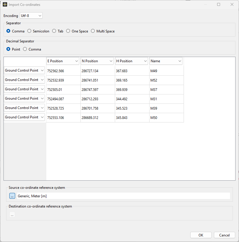
Once the GCPs are imported:
- Select one GCP in the list and localize its position in the 3D viewer by clicking the left mouse button. The list of reference images will be updated, and the active images including selected GCP will be shown in the viewer.
- Choose the Manual Target Mode icon or the Automatic Mode icon and centre the target by clicking with the mouse in the viewer. For locating the target discs the image should be zoomed as much as reasonable for visual interpretation.
- Choose at least 2 images (more than 3 are recommended) showing the same GCP and centre the target position in the viewer (Tip: you can switch between the individual images in the list by using the left and right arrow keys). The status signals Baseline and the Inliers turn into green, and the error of re-projection and depth is displayed in the GCP list.
- Activate the next GCP in the list and repeat the steps 1 – 3 until all GCP positions are localized.
Your GCP list should look like this:
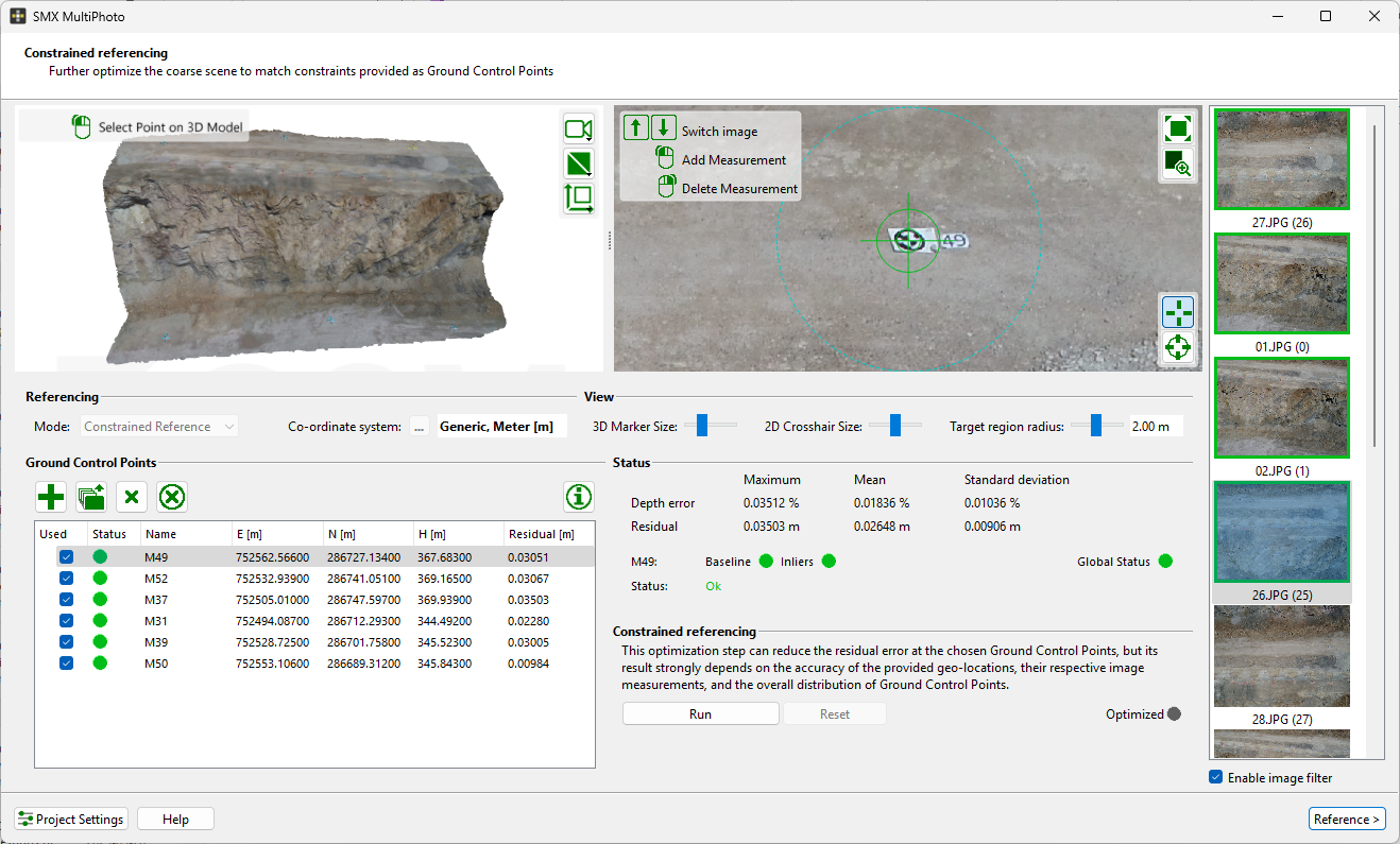
After all the GCP positions are localized the Status Information should be OK, and the Status Signal should be Green. Once you check the status information:
- Start Constrained Referencing by clicking the Run button.
- The Optimized signal should turn green once the optimization is completed.
- Check the error statistics. Click the Reference > button to finalize Constrained Referencing and perform Dense Reconstruction.
Once the Dense Construction process is completed, a 3D model with texture is generated and an output file (*.jm3x) is automatically saved.
Additional files according to the Project Settings are also generated at this stage. In this example a pdf report about the reconstruction process and an ortho-photo of the 3D model (jpg) are generated
Notice that Standard Referencing option is disabled in Referencing > Control Points after Dense Reconstruction is completed, since we already performed a Constrained Referencing.
- Inspect the 3D model in 3D Model view and click Exit to leave MultiPhoto.
This concludes the tutorial for Standard and Constrained Referencing Using Ground Control Points in MultiPhoto.