2 - Terrain Generator and Image Segmentation
1.0 Introduction
The Terrain Generator can be used to import digital elevation models and surface textures from satellite data. Image Segmentation can then be applied to the imported surface texture to automatically assign materials to the slope surface.
Topics covered in this tutorial:
- Import Terrain
- Topographic Lines
- Image Segmentation
- Select Faces by Filter
Finished Product:
The finished product of this tutorial can be found in the Tutorial 02 Terrain Generator and Image Segmentation data file. All tutorial files installed with RocFall3 can be accessed by selecting File > Recent Folders > Tutorials Folder from the RocFall3 main menu.
2.0 Geometry
2.1 Import Terrain
The Terrain Generator tool allows users to quickly create the slope geometry by importing a digital elevation model from satellite data. This feature can only be used when there is internet connection. The terrain location can be specified in several ways: 1) by directly searching a civic address; 2) by entering coordinates for the latitude and longitude; or 3) or by browsing through the provided map. This tutorial uses coordinates for the latitude and longitude.
To use the Terrain Generator:
- Open a new project in RocFall3.
- Select Analysis > Project Settings, go to the Methods tab and ensure the Analysis Type = Lump Mass. Click OK to close the dialog.
- Select Geometry > Import/Export > Import Terrain

- Set the Layer as Satellite.
- Set the Region Dimensions (km) to Custom
and enter:
- Width = 1.5 km
- Height = 1 km
- Enter the Center Coordinate as 38.86295534611765, -120.071928601074 and click Set. Alternatively, coordinates can be copied and pasted into the Center Coordinate text box.
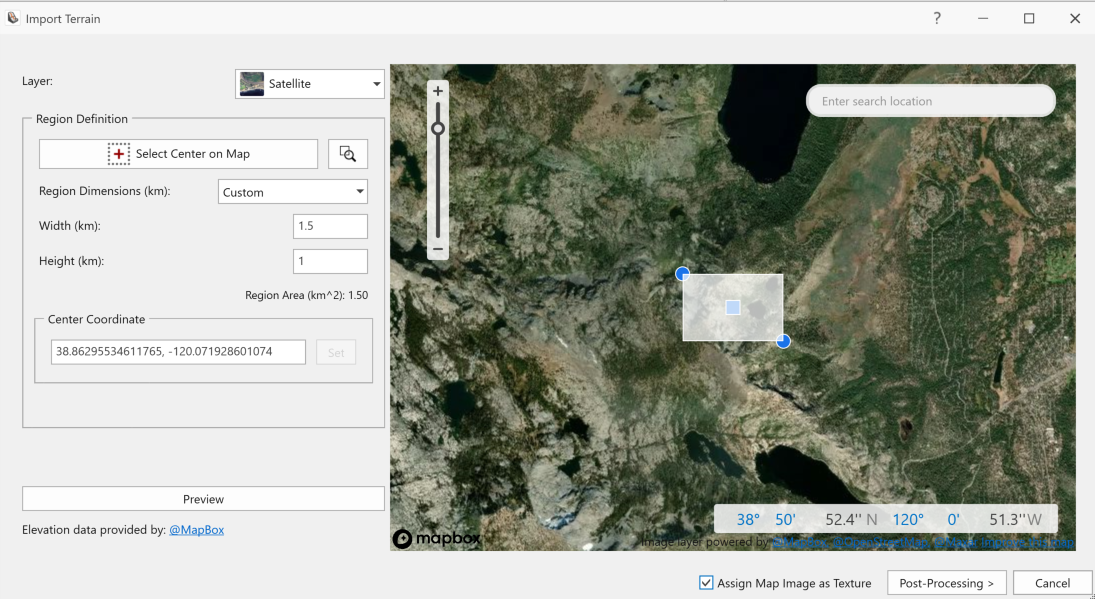
- Check Assign Map Image as Texture, and then click Post-Processing. Post-processing options include geometry simplification and repair.
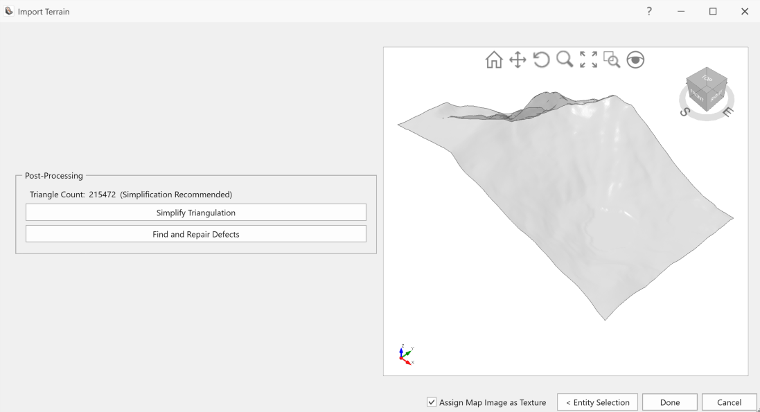
2.2 Simplify and Repair Geometry
- Select Simplify Triangulation.
- Under Simplification Level select Custom > By Triangle Count and enter 25000. Notice that the current number of surface triangles is around 215000, which is a large number that may lead to longer compute times.
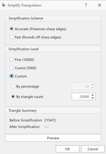
- Click OK.
Note: The number of surface triangles can always be viewed in the simplification tool by selecting Geometry > Surface Triangulation tools > Simplify Triangulation. - After being redirected back to the Import Terrain dialog, select Find and Repair Defects.
- Defect counts for the different defect types are shown. Click Repair and then Close.
Note: The Simplification and Repair Process does not remove the image texture on the terrain. Other geometry processes that can change the overall geometry of the surface can remove the image texture.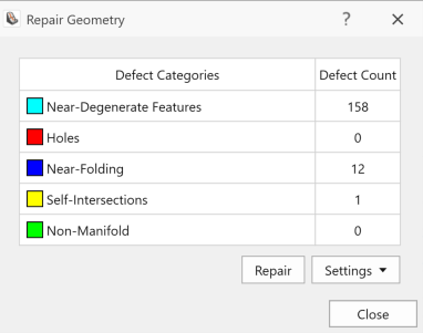
- Select Done to close the Import Terrain dialog.
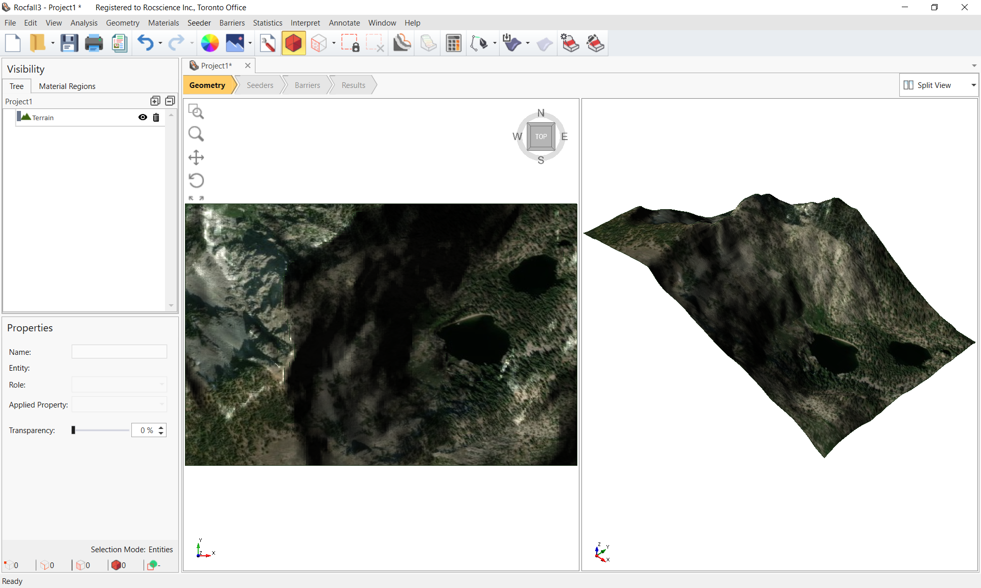
The default surface texture may be hard to see due its transparency. To change the transparency, select the Terrain entity in the Visibility Tree, then in the Properties pane change the Transparency to 0%. De-select the Terrain entity by either clicking in the viewport outside the slope or using the Clear Selection toolbar option.
2.3 Set Slope Surface
When done editing the slope:
- In the Visibility Tree, select the Terrain entity.
- Select Geometry > Set Slope Surface menu option.
2.4 Show Topographic Lines
Topographic lines can serve as a visual aid in the placement of elevation-dependent elements, such as materials, seeders, and protection systems.
- Select Annotate > Topographic Lines
 in the menu.
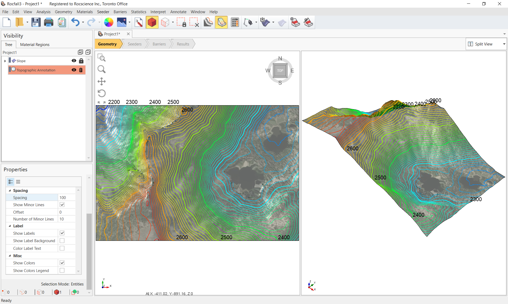
 - In the Visibility Tree, select the Topographic Annotation entity to access its properties in the Properties Pane below.
- Go to the Properties Pane, change the Spacing to 100 and check Show Colors.
3.0 Slope Materials and Seeder
3.1 Define Material Properties
Define 3 materials for this model.
- Select Materials > Define Materials
 in the menu.
 - Use values in the following table to define 3 materials.
Change the color of the water material to a Light Blue.
Name Normal Restitution
Distribution St. dev. / Rel.Min / Rel.Max Tangential Restitution Distribution St. dev. / Rel.Min / Rel.Max Friction Angle (o) Hard 0.7 Normal 0.04 / 0.12 / 0.12 0.85 Normal 0.04 / 0.12 / 0.12 20 Soft 0.5 Normal 0.04 / 0.12 / 0.12 0.8 Normal 0.04 / 0.12 / 0.12 20
Water 0.0 None - 0.0 None - 89
3.2 Add Material Regions
3.2.1 Automatically Assign Materials by Texture (Image Segmentation)
An imported surface texture can be segmented for defining different material regions. This feature is applied as follows to assign the Hard and Soft materials to the slope surface.
- Select Materials > Automatically Assign Materials by Surface Texture

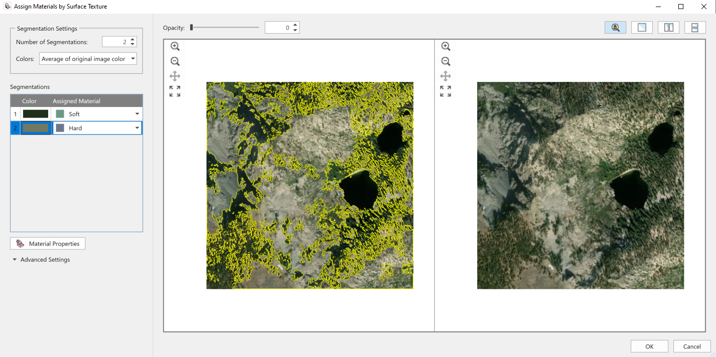
- Notice two images of the slope are shown in the dialog. The original image is shown on the right, and the segmented image is shown on the left.
- For the Number of Segmentations, use a value of 2. This field controls the number of segmented regions on the slope.
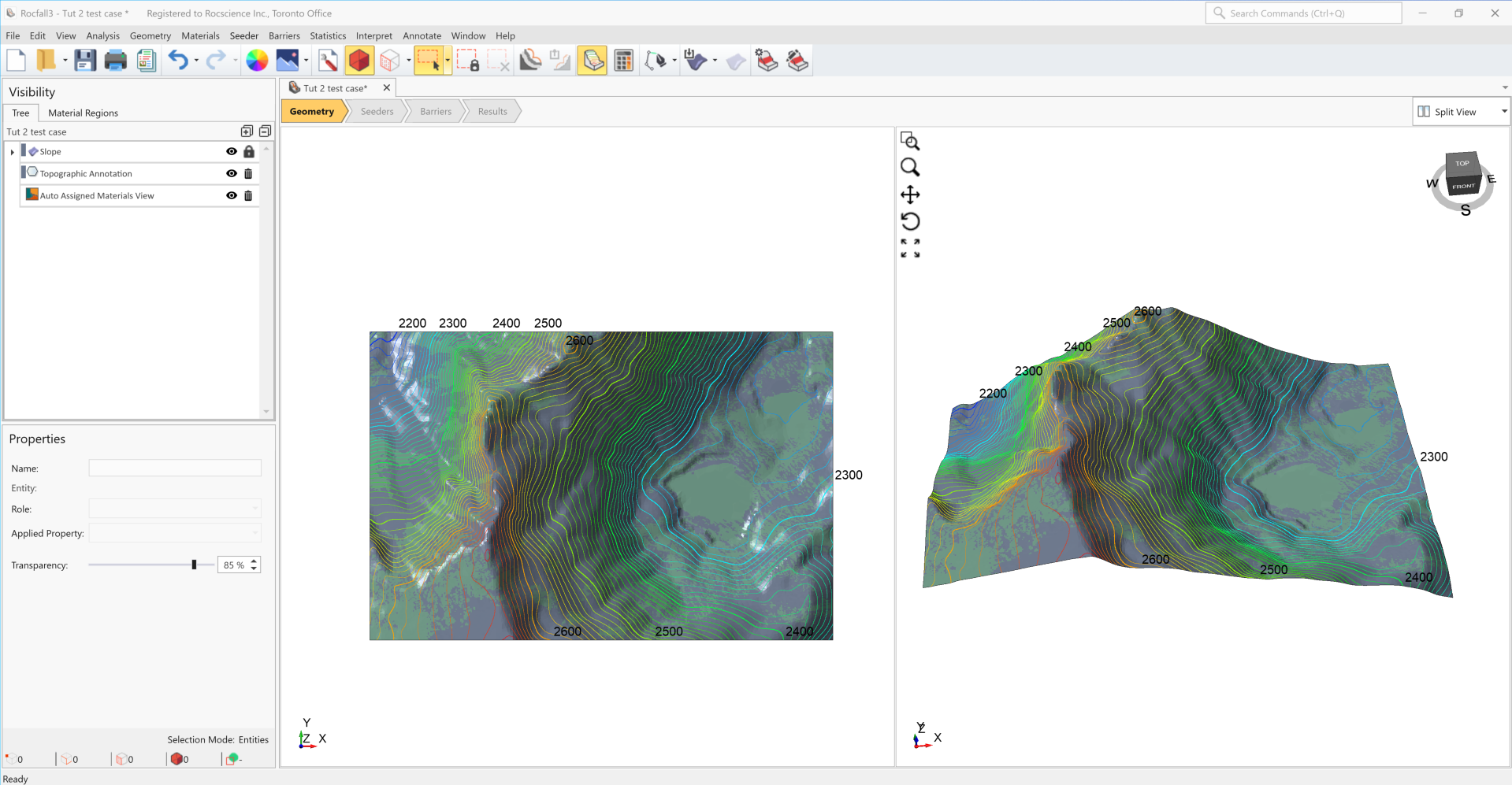
- Under the Segmentations section, a list of segments is provided, along with the corresponding assigned material property and the display colour for each segment. Apply the segmentation as shown below.
- Close the dialog by clicking OK.
The Image below illustrates the material assignment by image segmentation. For now, there are two lakes assigned with the Soft material property. The Water property can be defined for the two water bodies by manually implementing material regions (e.g., by drawing) and overriding the image segmentation.
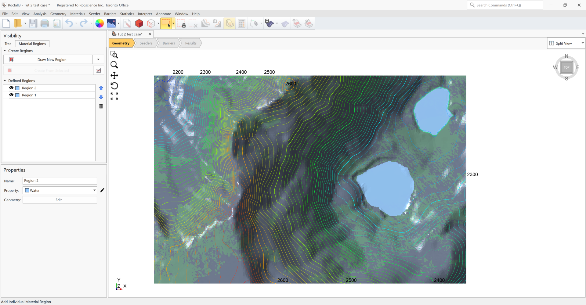
3.2.2 Drawing Water regions
- Select the Material Regions tab located next to the Tree tab in the Visibility pane.
- Click Draw New Regions.
- Select the Water Property and click OK.
- Now in Draw Polyline mode, draw a Water region by left-clicking around the outline of one of the lakes.
- Right-click and select Done when finished drawing.
- Repeat steps 2-5 to draw a Water material region for the second lake.
For exact coordinates of the material regions used in this tutorial, open the provided .txt files in the Tutorials folder or download the files linked below. Select Draw New Region, select the Water property, then after entering Draw Polyline mode, select the import option in the Edit Polyline dialog and import the Tutorial 02 Water Region 1.txt and Tutorial 02 Water Region 2.txt files for regions 1 and 2.
Click on the Tree tab in the Visibility pane to exit the Material Regions mode.
3.3 Add Line Seeder
- Change to the Seeders Flow Tab.
- Select Seeders > Define Seeder Properties in the menu.
- For Seeder Property 1, set the Number of Rocks to 300.
- Leave all other values at their default and click OK to close the dialog.
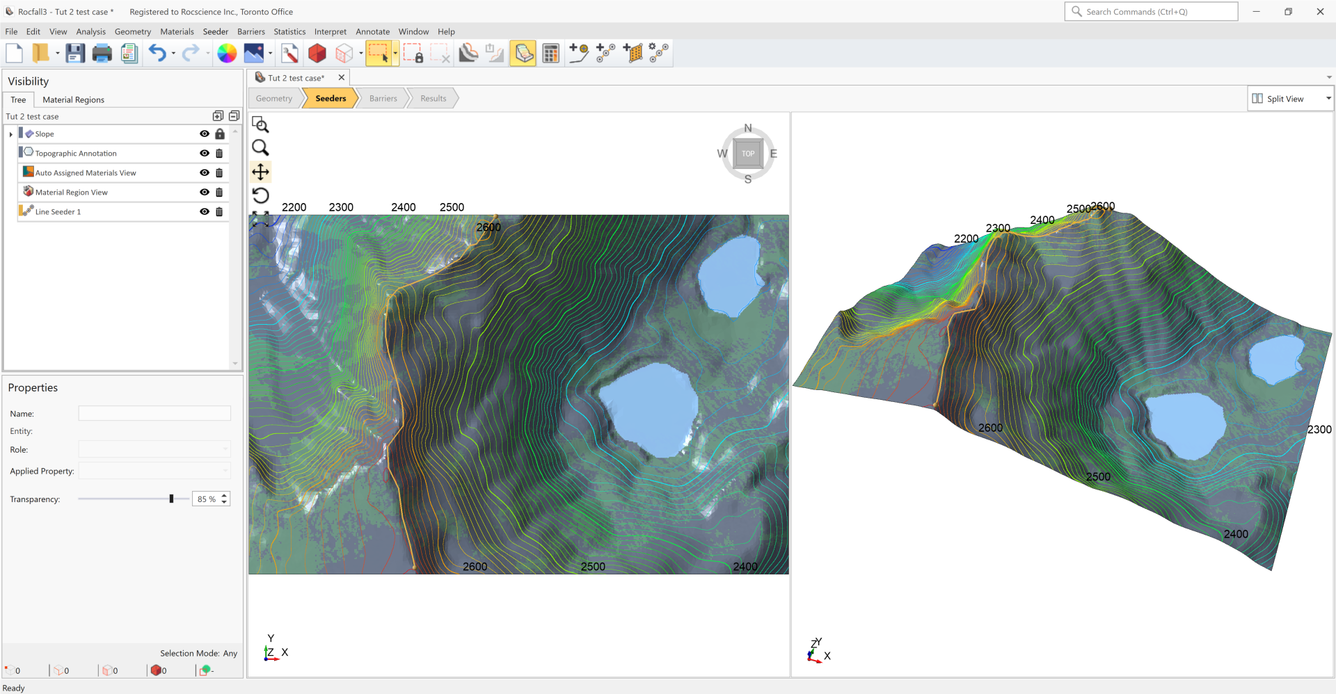
- Select Seeders > Add Line Seeder
 in the menu.
 - Select Height Above Surface and input a height of 3 m.
- Click Add Points on Viewport and draw the line seeder by left-clicking along the mountain ridge.
- Click Done once done drawing the line seeder.
- Click OK to close the dialog.
For exact coordinates of the line seeder used in this model, open the provided Tutorial 02 Line Seeder.txt file in the Tutorials folder. Alternatively, the .txt file can be saved by right-clicking the link and selecting Save Link As. To import values for a line seeder, first draw a polyline by selecting Geometry > Draw Polyline, and then import the provided .txt file in the Edit Table option. Select the Polyline entity in the Visibility Tree and then convert it into a line seeder by selecting Seeder > Add Line Seeder from Polyline.
4.0 Compute
- Click on the Compute
 icon in the toolbar (or select Analysis > Compute in the menu).
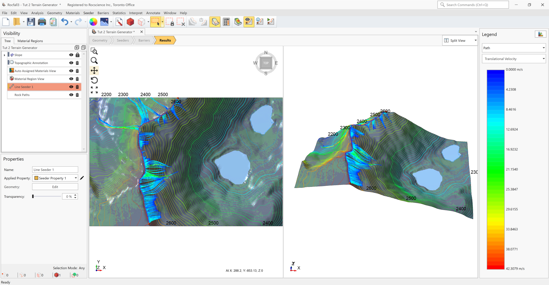
5.0 Results
This model is a great example that showcases the difference between 2D and 3D models. Rock paths are not confined to a 2D plane. Instead, they can curve and tend to congregate at local valleys.