4 - Rigid Body and Surface Texture
1.0 Introduction
This tutorial introduces the rigid body analysis method and how to apply a surface texture image to the slope surface.
Topics covered in this tutorial:
- Rigid Body Analysis Method
- Slope surface texture
- Area Seeders
Finished Product:
The finished product of this tutorial can be found in the Tutorial 04 Rigid Body and Surface Texture.r3DModel data file. All tutorial files installed with RocFall3 can be accessed by selecting
File > Recent Folders > Tutorials Folder from the RocFall3 main menu. By default all tutorials and verification files are installed in the folder C:\Users\Public\Documents\Rocscience\RocFall3 Examples.
2.0 Model
Start RocFall3 by selecting Programs > Rocscience > RocFall3 > RocFall3 from the Windows Start menu.
2.1 Analysis Type
-
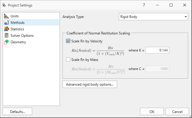
Select: Analysis > Project Settings

- In the Methods tab, select Rigid Body from the Analysis Type drop down.
- Enable Scale Rn by Velocity.
- Click Advanced rigid body options... and make sure Use Spheres v1.005 and earlier is unchecked.
- Click OK to save the Rigid Body Engine Advanced Options.
- Click OK to save the Project Settings.
2.2 Import Geometry
Import a provided *.obj file:
-
Select File > Import > Import Geometry
 or
Geometry > Import/Export > Import Geometry .
or
Geometry > Import/Export > Import Geometry .
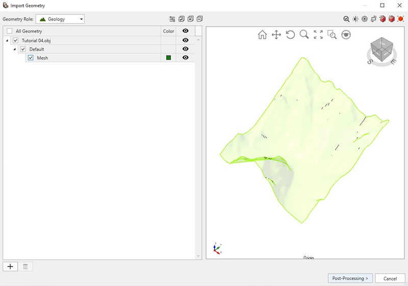
- Open the provided Tutorial 04.obj file in the Tutorials Folder. By default, the Rocscience Installer uses the folder C:\Users\Public\Documents\Rocscience\RocFall3 Examples\Tutorials.
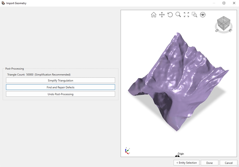
- The Import Geometry dialog displays a preview of the geometry. Select the Mesh object and click Post-Processing.
-
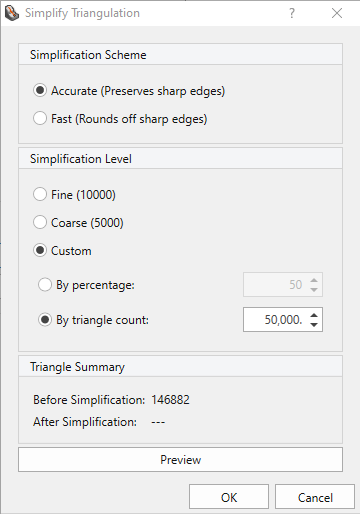
In the Post-Processing step, the geometry can be simplified and/or repaired. Click Simplify Triangulation > Simplification Level > Custom and enter a triangle count of 50,000. Click OK.
- Find and Repair Defects next. Click on Repair to remove all defects. Click Close.Some defects may remain after an initial iteration of repair. This is because several defects or several different types of defects may be overlapping or adjacent to one another. Simply Repair again to resolve.
- Click Done.
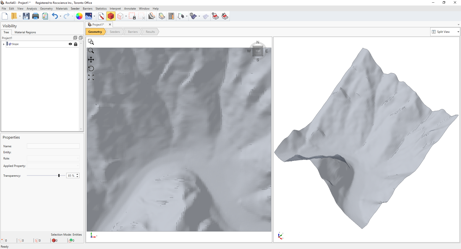
- When prompted to "set the imported surface as the slope", click Yes.
2.3 Apply Surface Texture
-
Select the Slope entity in the Visibility Tree. Whenever an entity is selected, it is highlighted in orange in the viewports.
- Select Geometry > Assign Texture to Surface

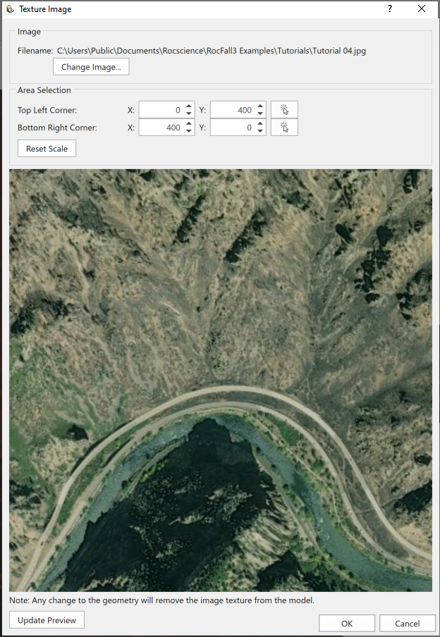
- Open the provided Tutorial 04.jpg file in the Tutorials folder.
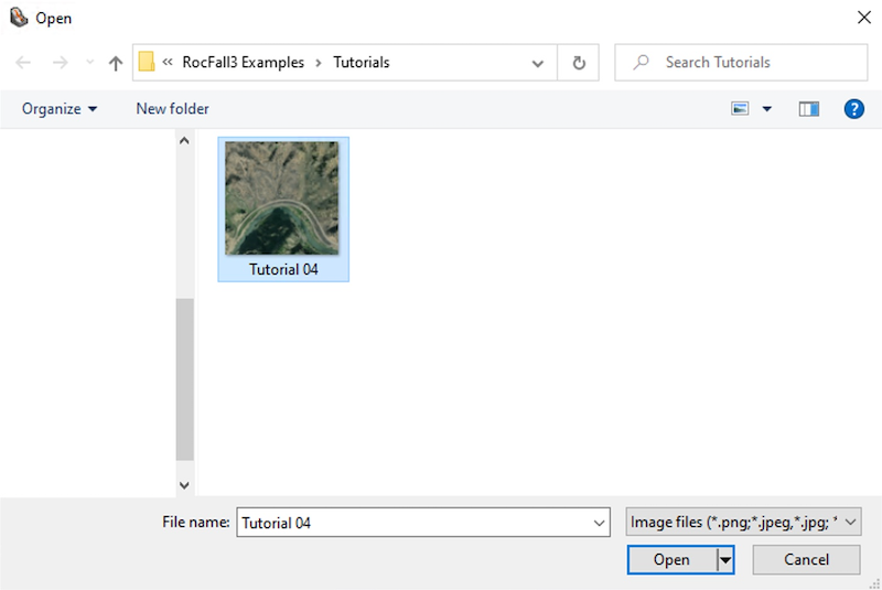
- The Texture Image dialog displays a preview of the image, which can be scaled and moved in this dialog to fit the slope geometry. The supplied image has already been adjusted to fit the slope. Click OK to accept and exit.
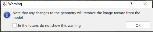
A warning appears noting that the surface texture would be removed with any changes to the geometry. This is because a surface texture is meant to be added after the underlying slope geometry has been finalized. If the slope geometry is modified after adding a surface texture, then the image would be removed. Click OK in the warning window to continue.
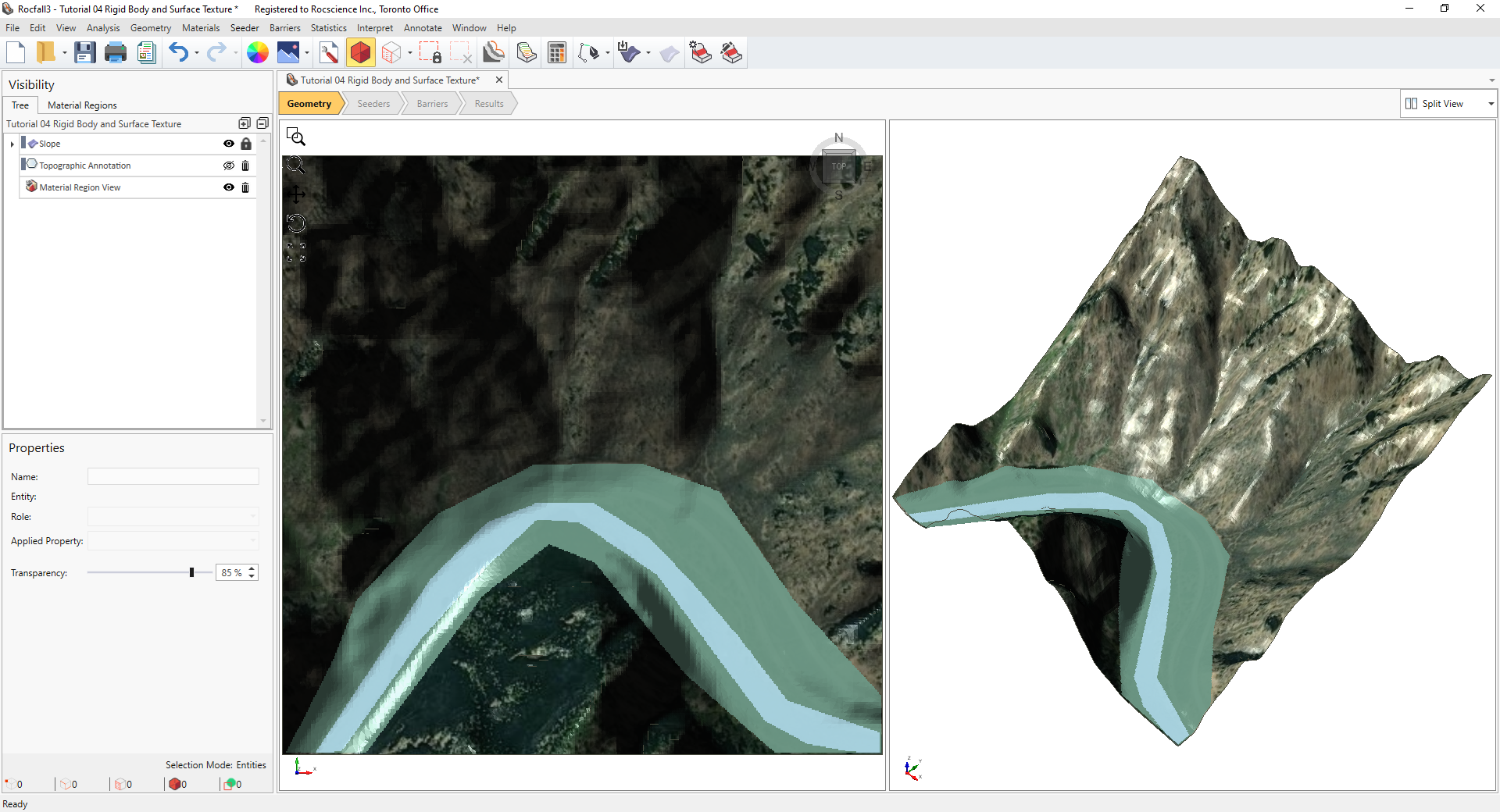
- Notice the Slope is still selected. De-select the slope by either clicking in the viewport outside the slope geometry, or by clicking Clear Selection on the toolbar.
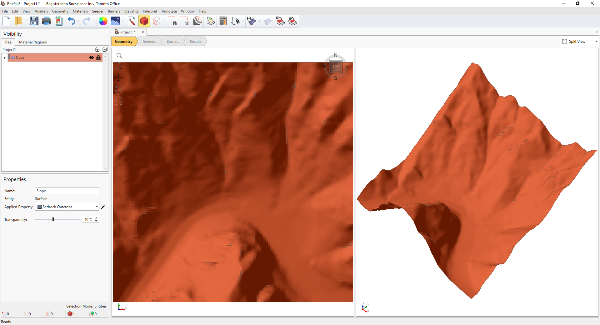
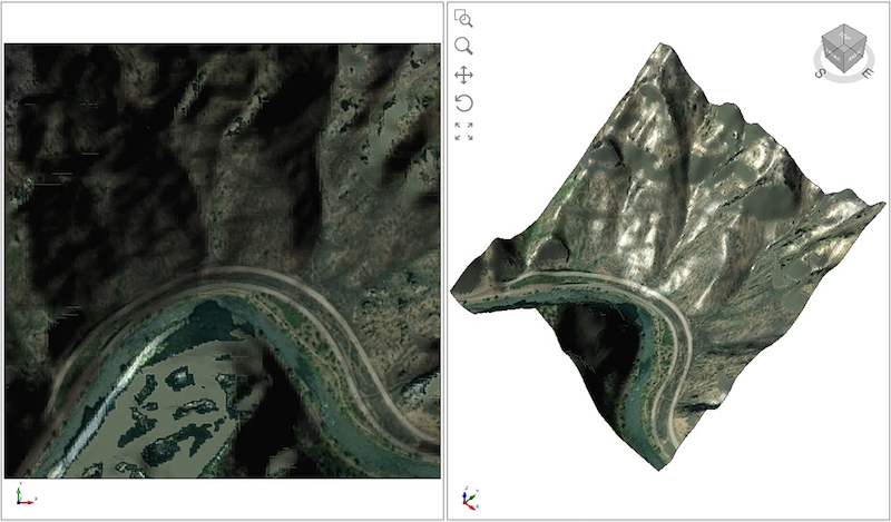
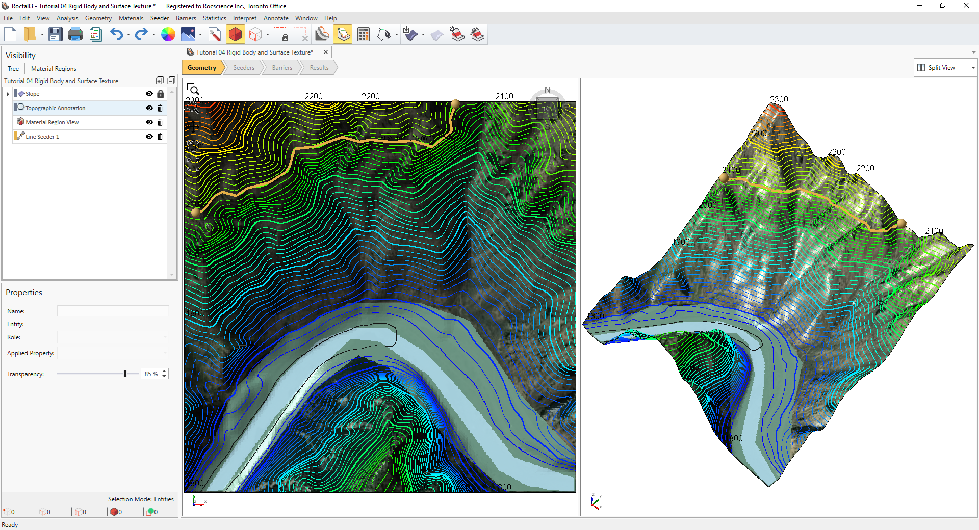
- The surface texture now overlies the slope geometry. Its visibility can be improved by adjusting the slope transparency. In the Visibility Tree, select the Slope entity. In the Properties pane below, decrease the transparency by dragging the slider or entering a lower value in the edit box. Change the slope transparency to 0%, then Clear Selection. The river and highway now can be seen very clearly.
2.4 Show Topographic Lines
Topographic lines can visually aid in the placement of elevation-dependent elements, such as material regions, seeders, and protection systems.
-
Select Annotate > Topographic Lines in the menu
or click on the Topographic Lines icon
 in the toolbar.
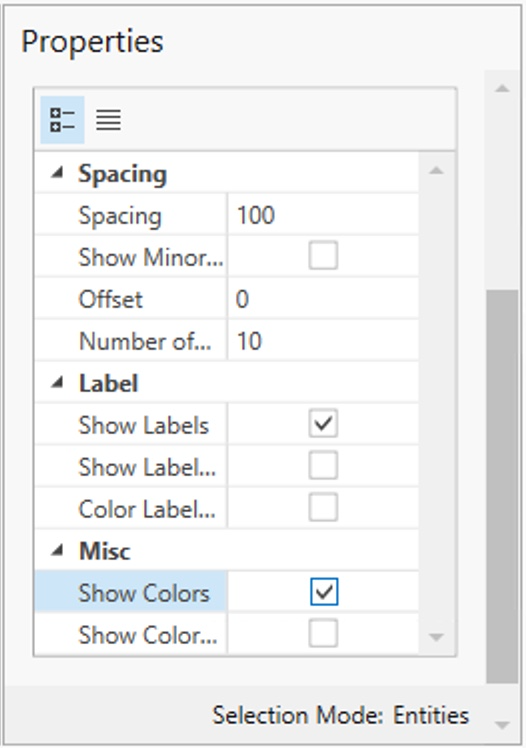
- In the Visibility Tree, select the Topographic Annotation entity to view its properties in the Properties pane below.
- In the Properties Pane, change the Spacing to 100 and make sure Show Colors is checked.
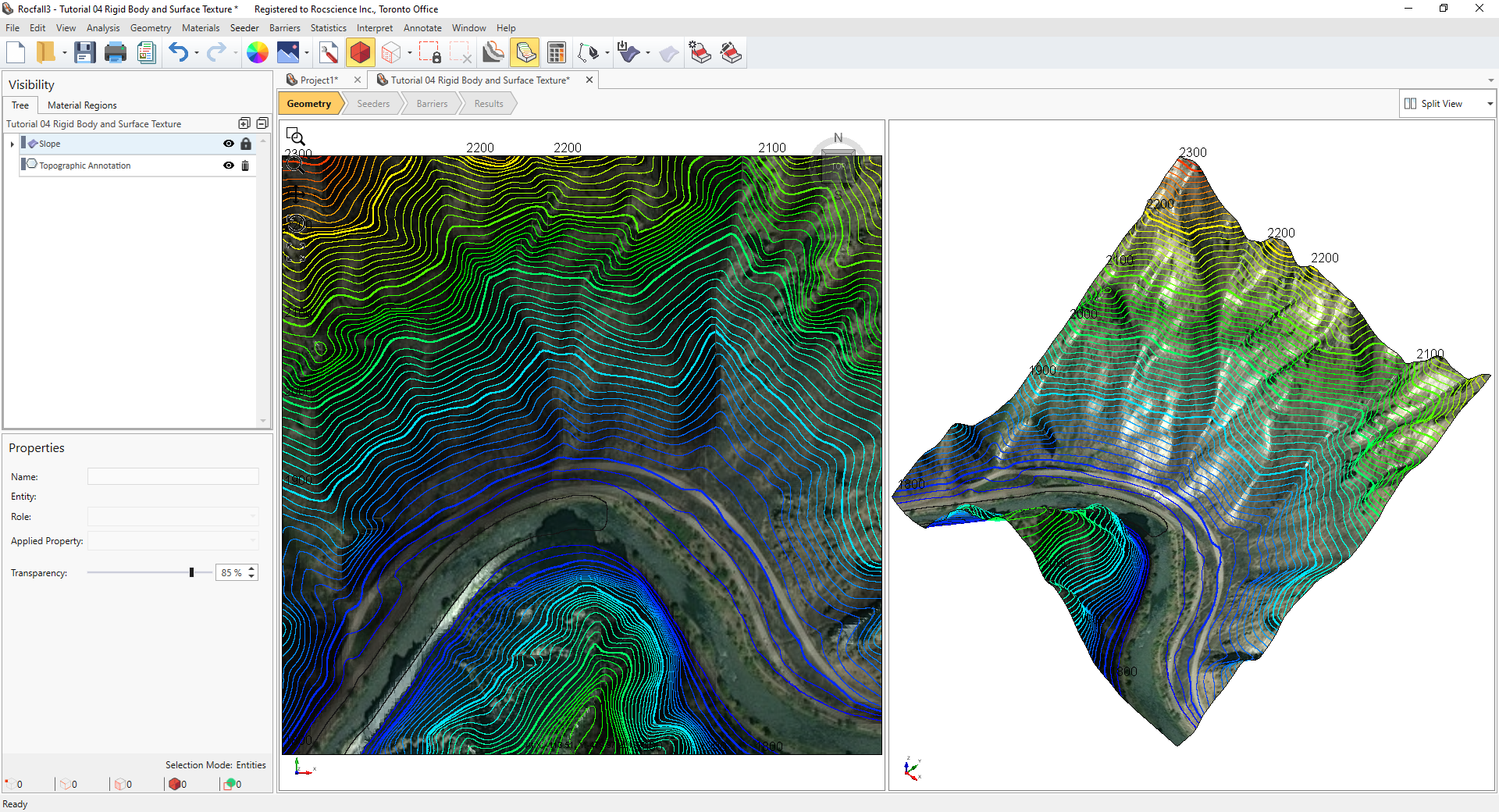
The visibility of the topographic lines can be turned on and off by selecting the "eye" icon in the Visibility Tree. 
2.5 Material Properties
- Select Materials > Define Materials

- Define the following 3 materials as shown in the table.
- Change the colour of the Water material property to a light blue.
Click OK when done defining material properties.
Name Normal Restitution
St. dev. / Rel.Min / Rel.Max Dynamic Friction St. dev. / Rel.Min / Rel.Max Hard 0.2 (Normal) 0.03 / 0.09 / 0.09 0.4 (Normal) 0.04 / 0.12 / 0.12 Soft 0.1 (Normal) 0.03 / 0.09 / 0.09 0.8 (Normal) 0.04 / 0.12 / 0.12 Water 0.0 (None) - 0.99 (None) -
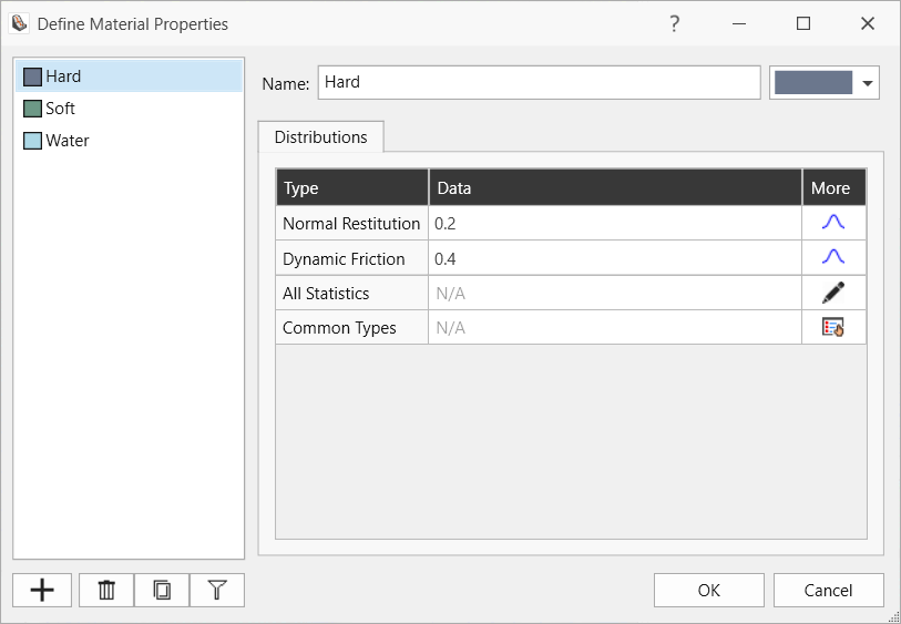
Define Material Properties: Hard Material
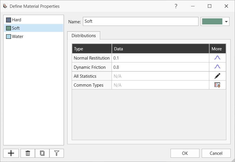
Define Material Properties: Soft Material
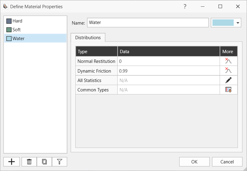
Define Material Properties: Water
2.6 Add Material Regions
- To add new material regions, select the Material Regions tab (located next to the Visibility Tree) or from the menu Materials > Edit Material Regions
 . This is where the overlay texture image will aid us.
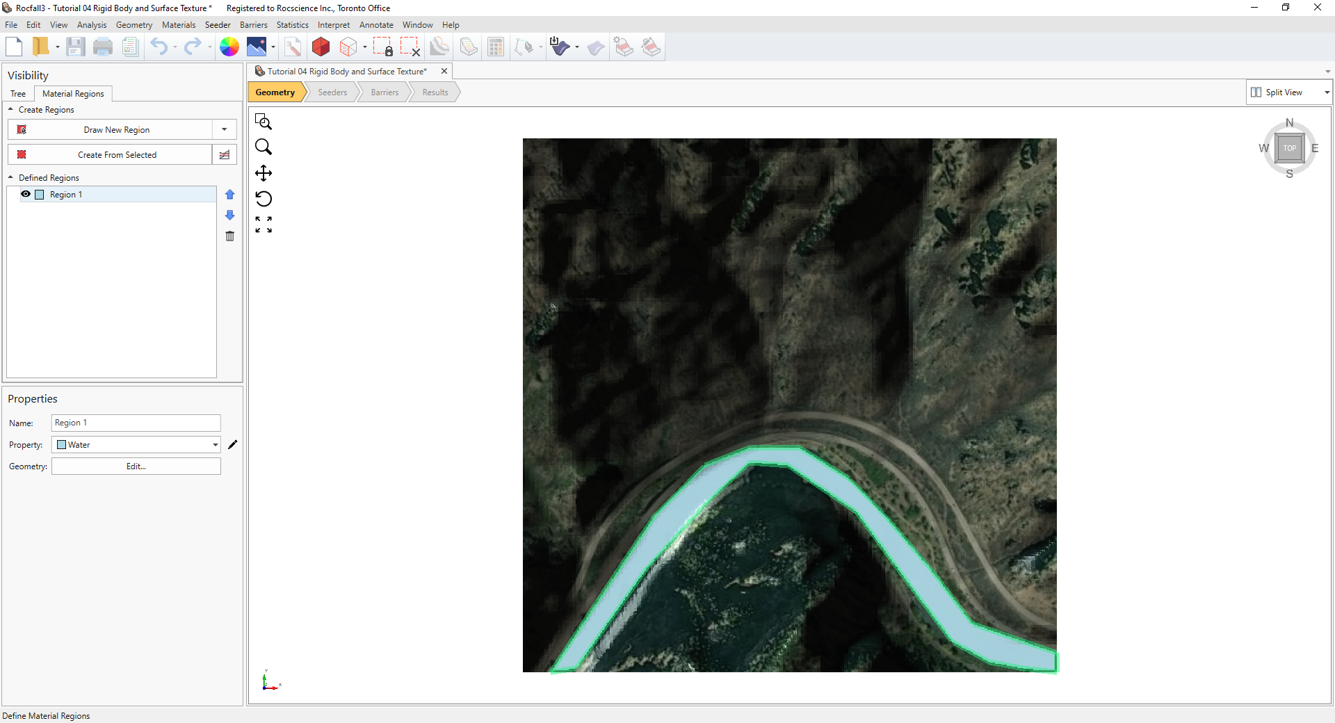
2.6.1 Define Water Region
- Select Draw New Region.
- Select the Water Property and click OK.
- We're now in the Draw Polyline mode for defining material regions using the Water material assignment. Roughly trace (left-click) round the river near the bottom of the slope. Alternatively, for exact coordinates, select the Edit Table button in the Draw Polyline pane, and then Import the following Tutorial 04 Water Region.txt file.
- When done drawing or importing the coordinates for the material region, right-click and select Done to exit drawing mode.
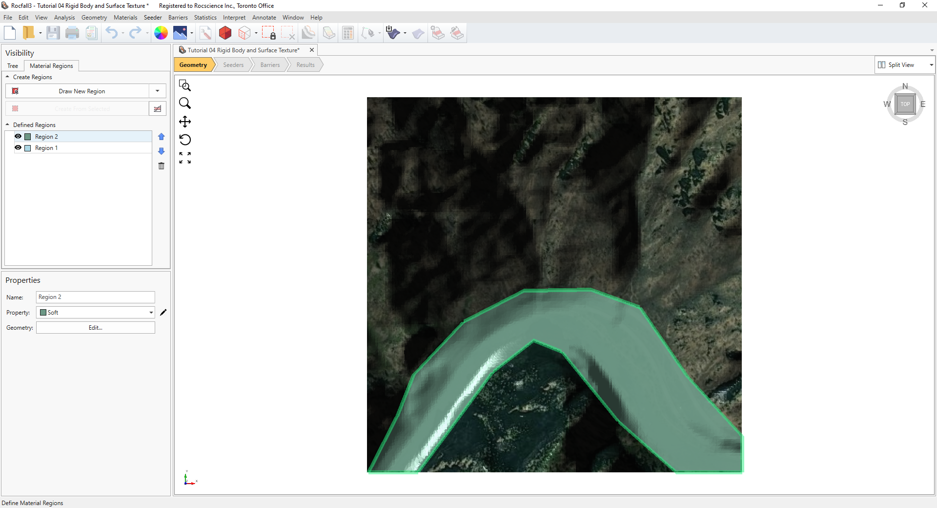
2.6.2 Define Soft Region
- Select Draw New Region.
- Select the Soft material property to use and click OK.
- Roughly trace around the flat areas around the river (including the highway). Alternatively, for exact coordinates of the material region, select the Edit Table button in the Draw Polyline pane, and then Import the following Tutorial 04 Soft Region.txt file.
- When done drawing or importing the coordinates for the material region, right-click and select Done to exit drawing mode.
2.6.3 Reorder Material Regions
Notice that the soft green region now overlies and hides the blue water region. This means the green region is currently the top material layer and its properties would be used in computations. Material layers can be re-ordered, as follows:
- In the Defined Regions list, select Region 1 (the water region). Click the Up arrow
 to move the water region to the top of the list and also to the top of all material layers.
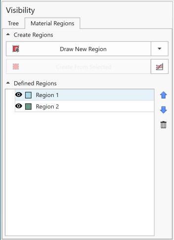
- Click on the Visibility Tree tab in the left pane to get out of the Material Regions mode.
2.7 Seeder Properties
- Select the Seeders workflow tab.
- Select Seeder > Define Seeder Properties
 in the menu. This opens up the Seeder Properties dialog.
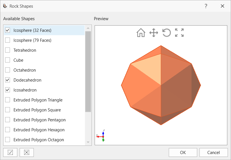
 - In the Seeder Properties dialog, under the Rock Shapes tab, select the Pencil Icon located next to shapes to edit the rock shapes to be used for the Seeder Property 1.
- In the Rock Shapes dialog, select the Icosphere (32 faces), Dodecahedron and Icosahedron shapes, and click OK to close the dialog.
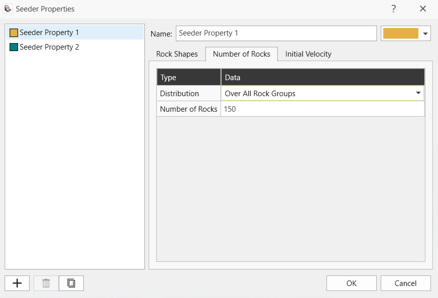
- Switch to the Number of Rocks tab. For Seeder Property 1, change the Number of Rocks to 150. Use default values for all other parameters, including zero initial velocity, so that all rocks will be free falling from the seeder location.
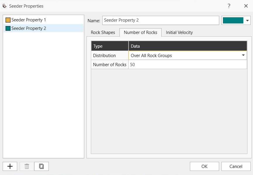
- Click on the Add
 button to add a new seeder property.
 - For this Seeder Property 2, repeat steps 3 and 4 above to define the rock shapes.
- Switch to the Number of Rocks tab and change the Number of Rocks to 50.
- Click OK to save the seeder properties and to exit the dialog.
2.8 Add Seeders
A line seeder and an area seeder are added to this tutorial model.
2.8.1 Line Seeder
- Turn on the visibility of the topographic lines by pressing the eye icon in the Visibility Tree next to the topographic lines entity.
- Select Seeder > Add Line Seeder

- The Add Line Seeder dialog opens. Make sure Seeder Property 1 with 150 rocks is selected for Property.
- Select Height Above Surface for the Elevation (Z Value) dropdown and enter 1 m.
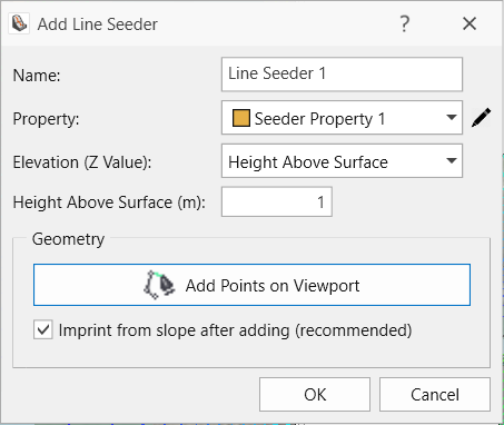
- Select Add Points on Viewport. In the viewport showing the model top view, trace (left-click) along the 2100 m topographic line as shown below.
- When done drawing, right-click and select Done.
- Click OK to save and exit the Add Line Seeder dialog.
An alternative to drawing the line seeder is to use the exact coordinates as adopted in this tutorial. Import a polyline by selecting Geometry > Draw Polyline, click the Edit Table button, Import the following Tutorial 04 Line Seeder.txt file, right-click and select Done, click on the polyline entity in the Visibility Tree, navigate to Seeder > Add Line Seeder from Polyline, and finally click OK.
2.8.2 Area Seeder
- Select Edit > Selection Mode > Faces Selection

- Select Edit > Selection Region Mode > Lasso Region
 . Steps 1 and 2 are used to allow the selection of slope faces using lasso selection.
 - In the viewport showing the model top view, left-click and drag your mouse over the area of interest near the Northeast corner. The lasso selection should appear in orange for the slope faces that are selected.
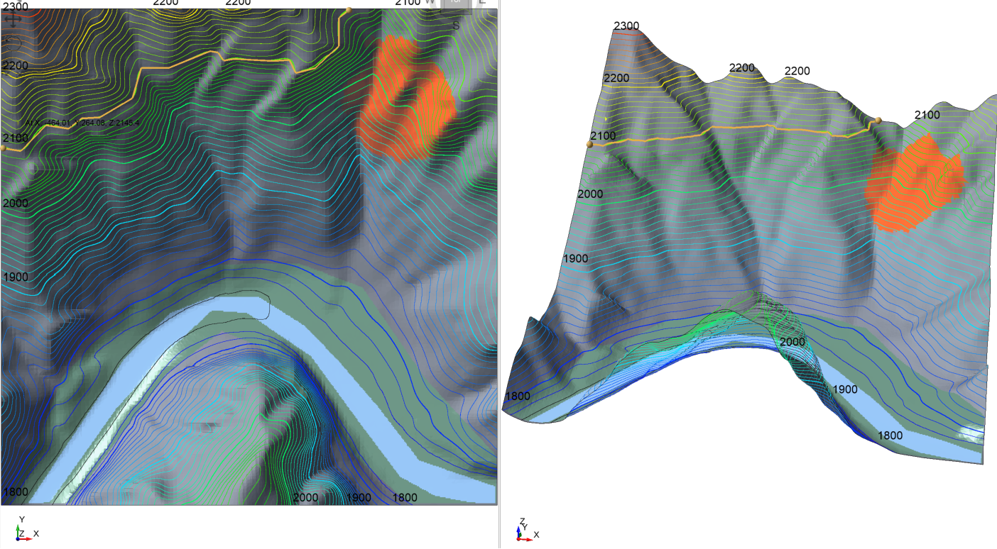
Lasso selection for area seeder - Select Seeder > Add Area Seeder from Selection

- Similar to what was done for the line seeder, select the Height Above Surface from the Elevation (Z Value) dropdown and enter 1 m.
- Select Seeder Property 2 from the Property dropdown menu.
- Select OK.
3.0 Compute
- When ready to compute, select Analysis > Compute

4.0 Results
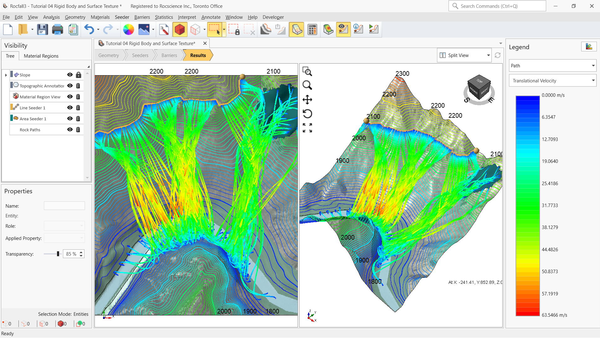
- Click on the Results workflow tab and observe the path results.
With the aid of the texture overlay, we can easily see that the rocks from the area seeder on the right would stop after hitting the river, but a small portion of the rocks from the line seeder on the left would hit the highway.