8 - Retaining Wall with Multi-Layer Backfill
1.0 Introduction
In this tutorial, a cantilever wall with multiple layers of backfill is designed using the AASHTO ASD standard. A step-by-step guide through the design process is provided.
Topics Covered:
- Cantilever Wall Design
- AASHTO ASD standard
- Multi-layer non horizontal backfill
Finished Product:
The finished product of this tutorial can be found in the Tutorial 8 folder. All tutorial files installed with RSWall can be accessed by selecting File > Recent Folders > Tutorials Folder from the RSWall main menu.
2.0 Getting Started
- Open the RSWall program.
- In the Welcome dialog, select:
- Wall template = Cantilever Wall
Design standard = AASHTO (ASD)
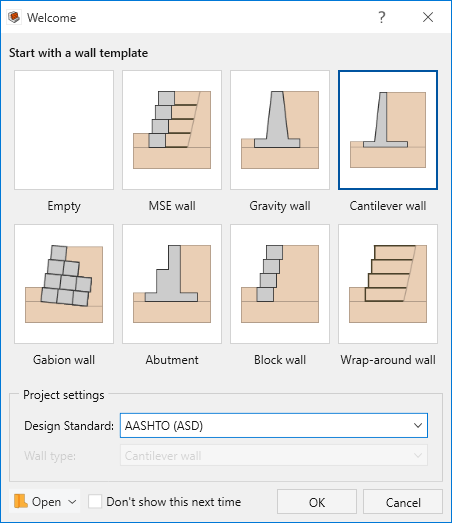
- Click OK.
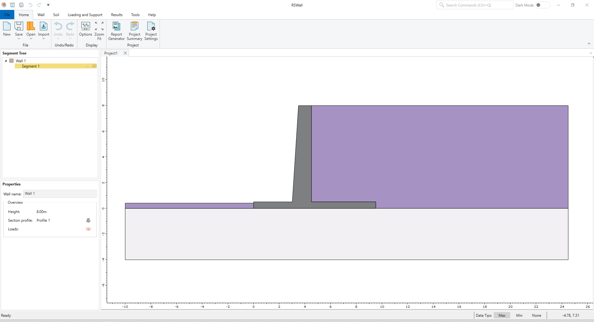
A Cantilever wall will be created with the default values of the program. These will be modified later in the tutorial.
3.0 Project Settings
- In the Home ribbon, select Home > Project > Project Settings

- In the Units
 tab, confirm that the Units are set to Metric, stress as kPa.
 Select the Wall type
 tab. Note that Cantilever wall is selected. Keep the selection as is.
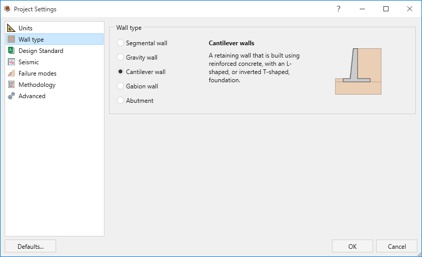
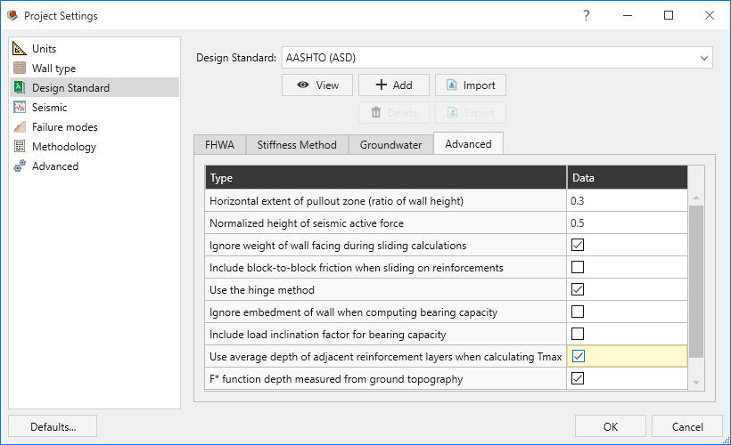
- Select the Design Standard
 tab.
tab.- Confirm that the design standard is set to AASHTO (ASD).
- Select the Advanced tab.
- Tick the Ignore weight of wall facing during sliding calculations checkbox.
Tick the Use average depth of adjacent reinforcement layers when calculating Tmax checkbox.
Select the Failure modes
 tab and keep the default selections for External stability.
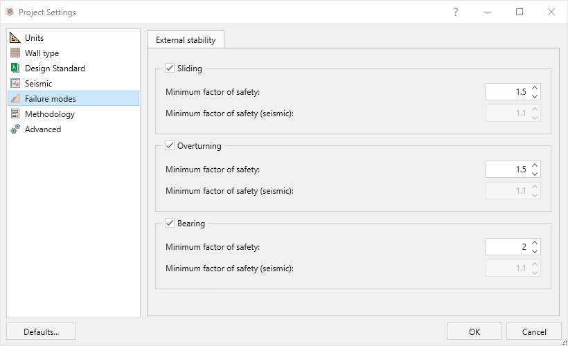
Select the Methodology
 tab and confirm the Active Pressure Method is Coulomb method.
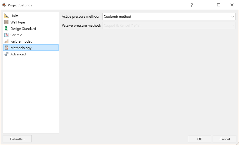
- Click OK to close the dialog.
4.0 Wall
In this part of the design process, we define the wall profile of the model.
- Go to the Wall ribbon.
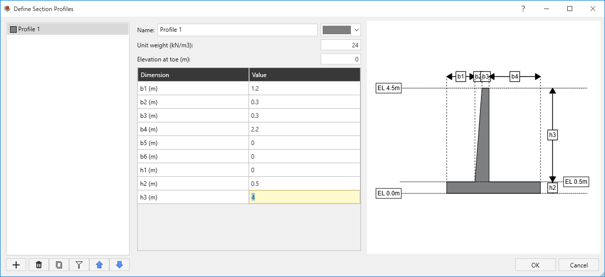
- Select Wall > Wall Profile > Define Section Profile

- Define the dimensions of the Cantilever wall as follows:
- Unit weight (kN/m3) = 24
- Elevation at toe (m) = 0
| Dimension (m) | Value |
| b1 | 1.2 |
| b2 | 0.3 |
| b3 | 0.3 |
| b4 | 2.2 |
| B5 | 0 |
| B6 | 0 |
| h1 | 0 |
| h2 | 0.5 |
| h3 | 4 |
- Click OK to close the dialog.
- Wall > Base > Define Base Strength

- For Bearing capacity select User-Specified and enter Ultimate bear capacity = 200 kPa
Select Contact with soil = Cast on Sand
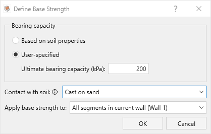
- Click OK to close the dialog.
5.0 Soil
In this part of the design process, we define the soil properties and assign them to different regions.
- Go the Soil ribbon.
- Select Soil > Soil Geometry > Backslope Topography

- Confirm Terrain profile = Infinite
Enter Slope angle = 20 degrees
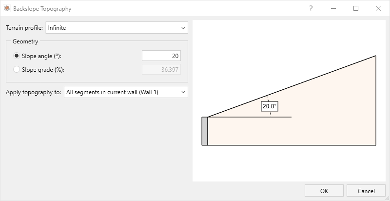
- Click OK to close the dialog.
- Select Soil > Soil Geometry > Front Face Topography

- Confirm Terrain profile = Infinite and Slope angle = 0 degrees
- Enter Embedment depth = 1.2 (m).
Make sure Consider passive resistance option is unchecked.
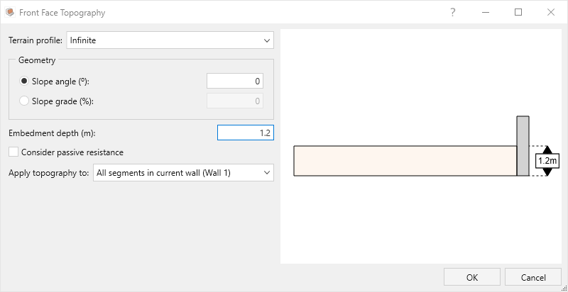
- Click OK.
- Select Soil > Soil Geometry > Soil Profile

In the Soil Profile dialog, enter:
- Horizontal reference point = At top of wall.
- Vertical placement by = Height from bottom.
- Define slope by = Angle.
- Click on + Add Boundary twice to add two rows for the boundaries between three layers of backfill, and define Y and Angle for each boundary, as shown below:
Y (m) Angle (o) 0 20 1.2 20 We are essentially picking a reference point and an angle to draw the boundary. We made it easy to define the reference point by providing default values for X depending on the choice of “Horizontal reference point.”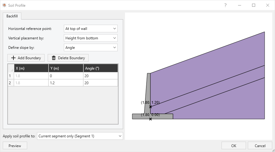
- Click OK to close the dialog.
- Select Soil > Groundwater > Define Groundwater

- Tick the checkbox for Include water table.
- For Water Profile select Differential and enter:
- Backslope water elevation = 2.2 m
Front face water elevation = 1.2 m
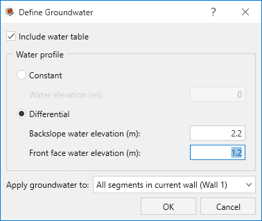
- Click OK.
Select Soil > Soil Conditions > Define Soil Properties

- Define the soil properties in General tab, as shown below:
Soil name\Property Unit Weight (kN/m3) Saturated Unit Weight (kN/m3) Friction Angle (o) Soil-Structure friction Angle (o) Cohesion (kPa) Layer 1 19 19 28 24 0 Layer 2 20 20 30 26 0 Layer 3 21 21 32 28 0 Foundation 19 19 28 24 5 - For the Foundation layer, select the Advanced tab and enter Coefficient of adhesion = 1.
- Click OK to close the dialog.
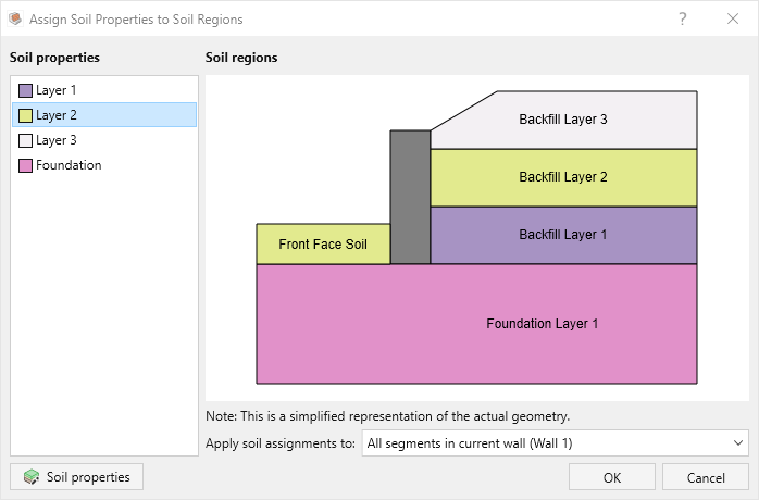
- Select Soil > Soil Conditions > Assign Soil Properties

- Assign the properties as follows:
- Front Face Soil = Layer 2
- Foundation Layer 1 = Foundation
- Backfill Layer 1 = Layer 1
- Backfill Layer 2 = Layer 2
Backfill Layer 3 = Layer 3
- Click OK to close the dialog.
- Assign the properties as follows:
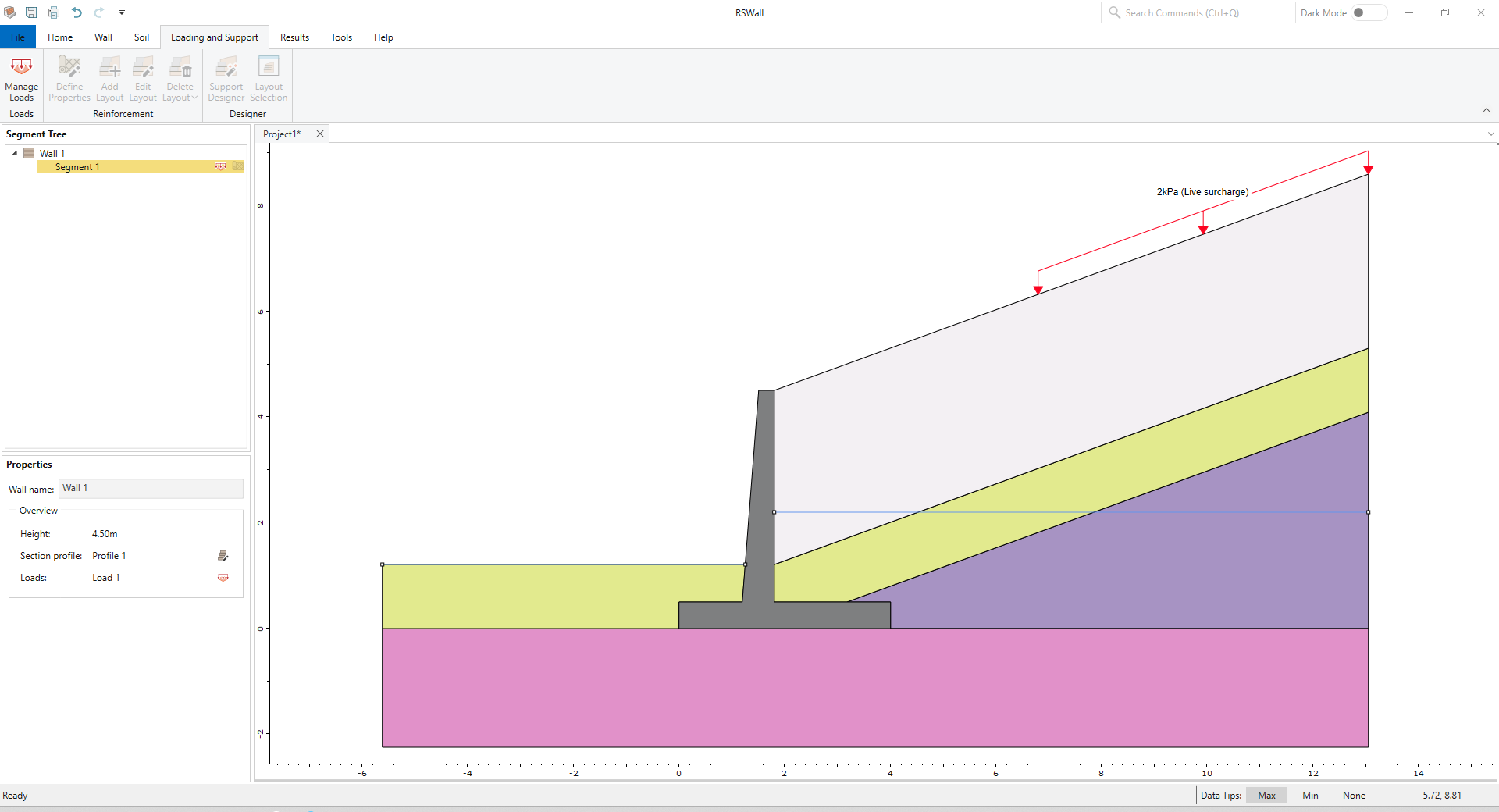
6.0 Loading and Support
In this part of the design process, we will define a live load, our reinforcement properties and arrangement.
- Go the Loading and Support ribbon.
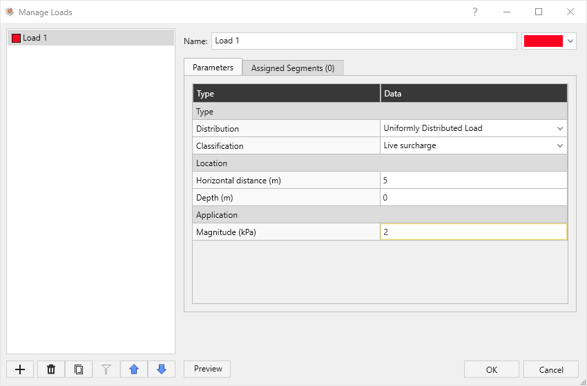
- Select Loading and Support > Loads > Manage Loads

- In the Parameters tab:
- For Type of the load:
- Distribution = Uniformly Distributed Load
- Classification = Live surcharge
- For Location of the load:
- Consider Horizontal distance = 5 (m)
- Depth = 0 (m)
- For Application:
Magnitude = 2 (kPa)
- For Type of the load:
- Select the Assigned Segments tab and assign the load to Segment 1.
- Click OK.
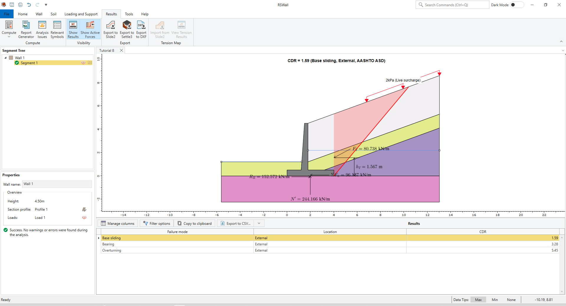
7.0 Results
- Select the Result ribbon.
- Select Results > Compute > Compute
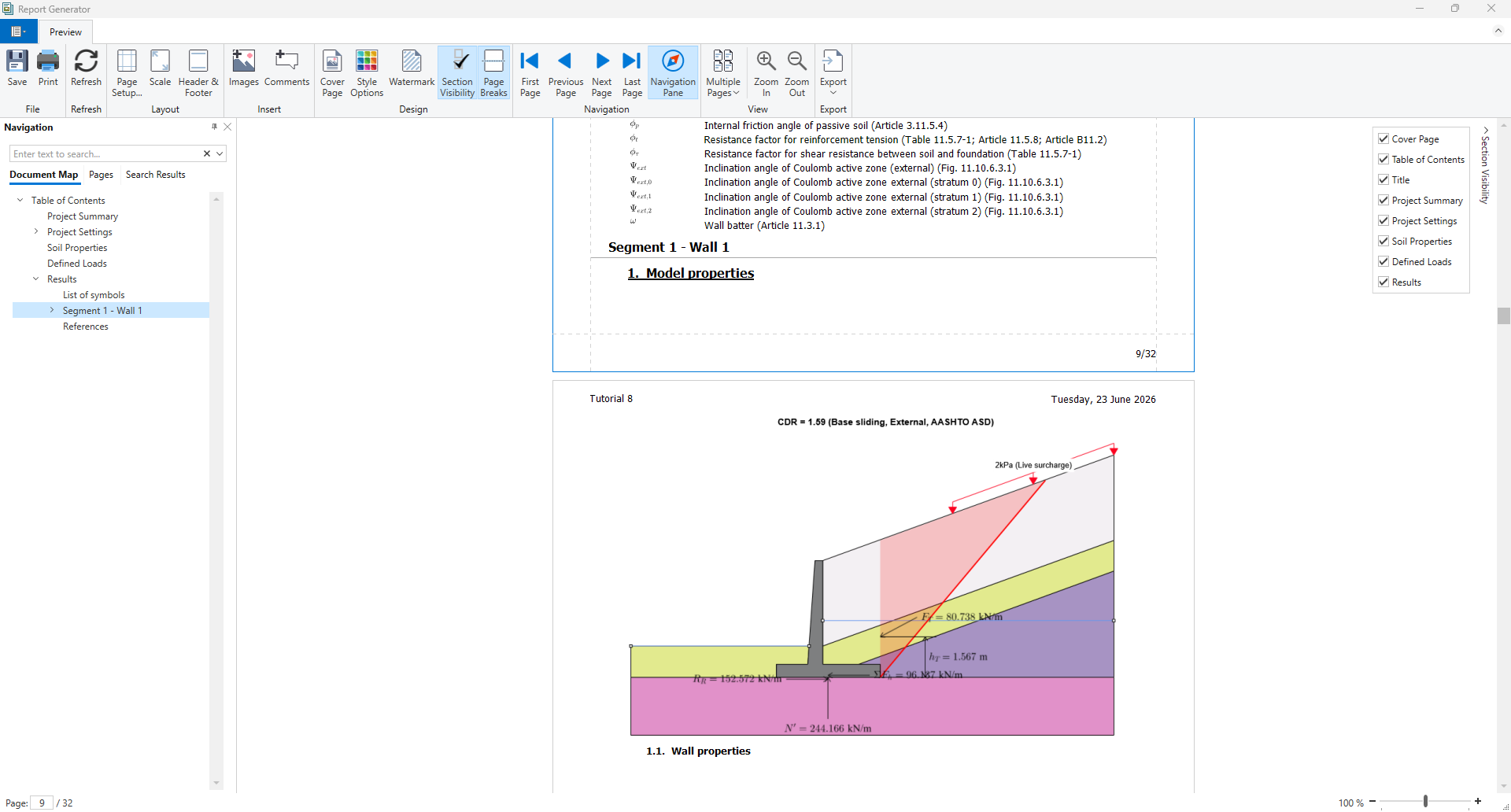
The results are shown below. The base Sliding failure mode controls the analysis for External stability.
- Select Results > Compute > Report Generator

- Report Generator in RSWall provides all the hand calculations for the output results of the RSWall program.
In the Navigation tree, click on the Results section.
- Click OK to close the dialog.