7 - Support Designer
In this tutorial, the reinforcement layout of a MSE wall is generated using the Support Designer.
Topics Covered:
- Generate simple layout with 1 reinforcement type
- Generate cost efficient layout with 2 reinforcement types
- Support designer wizard
- Overall Slide2 Stability Analysis
Finished Product:
The finished product of this tutorial can be found in the Tutorial 7 folder. All tutorial files installed with RSWall can be accessed by selecting File > Recent Folders > Tutorials Folder from the RSWall main menu.
1.0 Getting Started
This section will cover the steps to create a new block wall with three reinforcement types
- Open RSWall and select Empty from the wall template options.
Set the Design standard to AASHTO 2024 and Wall type to Segmental Wall.
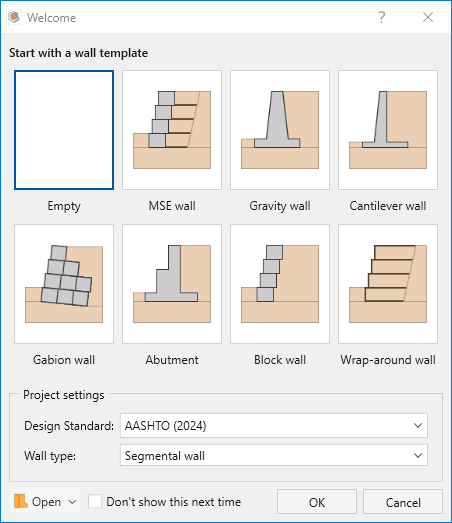
- Click OK.
- Save the file to a location of your choice (File > Save) and with a file name of your choice.
2.0 Wall Properties
Go to the Wall ribbon.
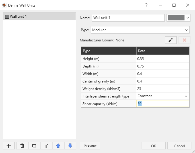
- Select Wall > Wall Profile > Define Wall Units

- In the Define Wall Units dialog, edit the parameters of “Wall unit 1” as follows:
- Height (m) = 0.35
- Depth (m) = 0.75
- Width (m) = 0.4
- Center of gravity (m) = 0.4
- Weight Density (kN/m3) = 23
- Interlayer shear strength type = Constant
- Shear capacity (kN/m) = 50
Click OK to apply your changes.
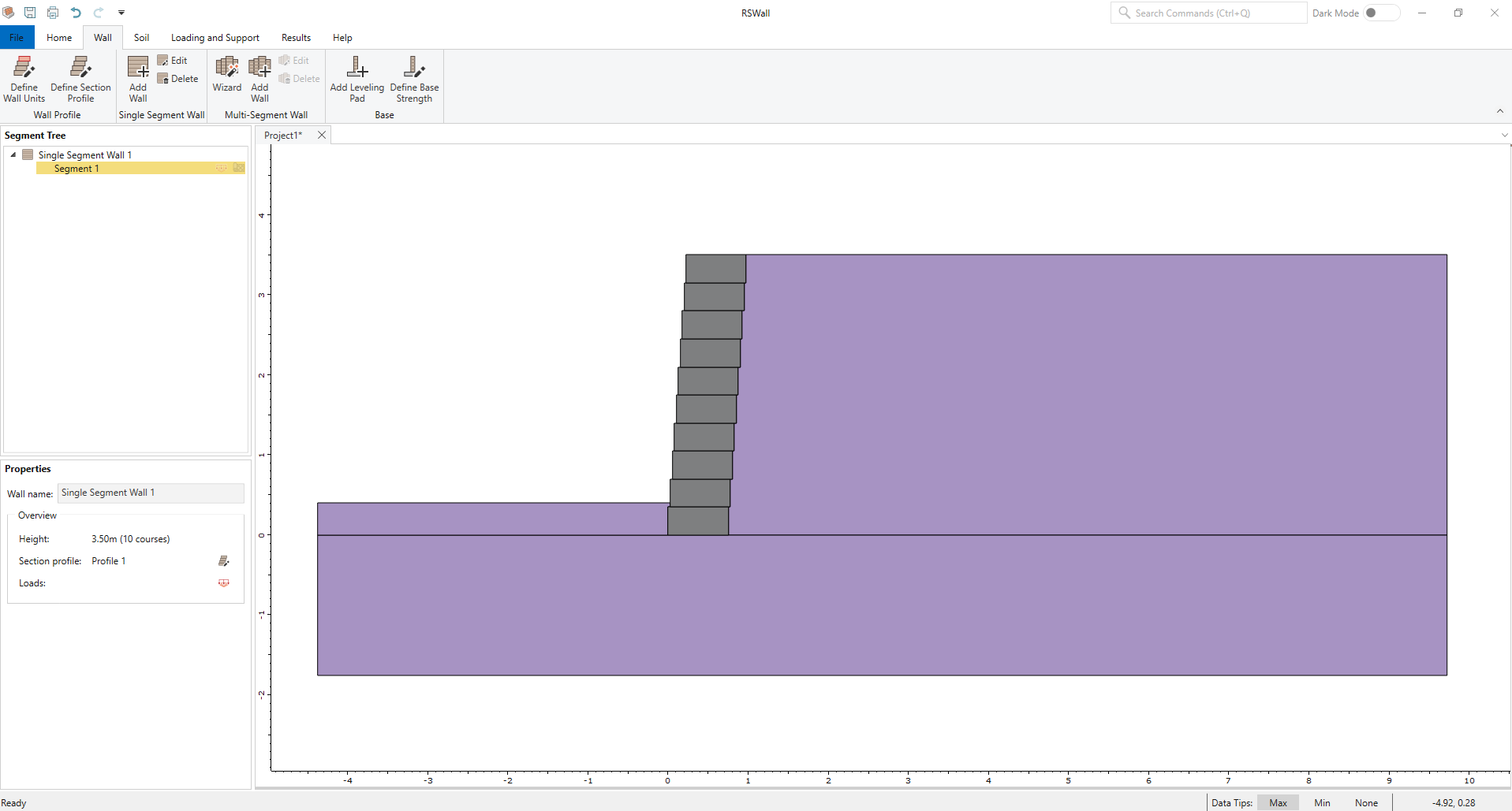
Select Wall > Single Segment Wall > Add Wall
 from the tool bar to open the Add Wall dialog. Ensure there are 10 blocks in the wall profile.
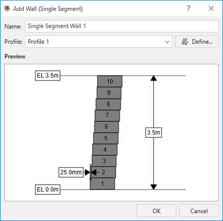
- Click OK to add a wall.
3.0 Soil Properties
Go to the Soil ribbon.
- Select Soil > Soil Geometry > Front Face Topography

- Make sure the Terrain profile is Infinite.
Set the Embedment depth to 0.7 m.
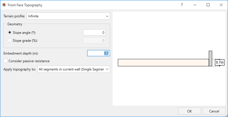
- Click OK.
Select Soil > Soil Geometry > Backslope Topography and ensure the Terrain Profile is set to Infinite.
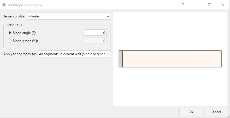
- Click OK to close the dialog.
Select Soil > Soil Conditions > Define Soil Properties
 and ensure that the following soil properties are assigned to each soil layer:
Soil name/Property Unit Weight (KN/m3) Friction Angle (o) Soil-Structure friction Angle (o) Cohesion (kPa) Soil 1 20 30 20 0 Soil 2 22 32 26 0 Soil 3 21 30 22 10 - Click OK to close the dialog.
- Select Soils > Soil Conditions > Assign Soil Properties

Assign Soil 2 to Backfill Layer 1 and Soil 3 to Foundation Layer 1.
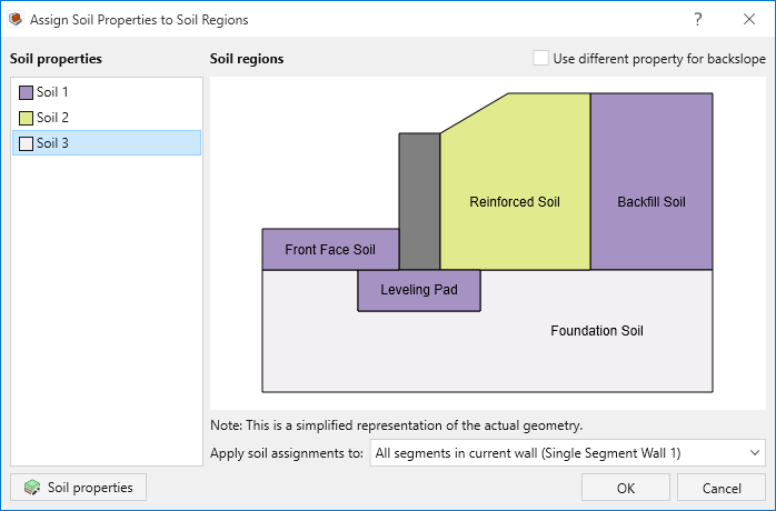
- Click OK.
4.0 Loading and Support
Go to the Loading and Support ribbon.
- Select Loading and Support > Reinforcement > Define Properties

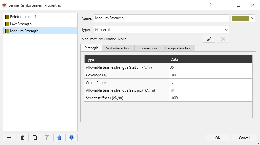
- In the Define Reinforcement Properties dialog, there is a default Reinforcement 1. In the Strength tab, change the Allowable tensile strength (static) to 40 kN/m, and in the Connection tab, change the Connection strength to 14 kN/m.
- On the bottom left of the dialog, click Add
 twice to add two new reinforcement types. Set their names to Low strength and Medium strength. Then set Type to Geotextile for both. Define the support properties with the parameters in the following table:
| Low strength | Medium strength | |
| Allowable tensile strength (static) (kN/m) | 18 | 35 |
| Creep factor | 1.4 | 1.4 |
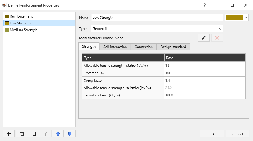
- Click OK to close the dialog.
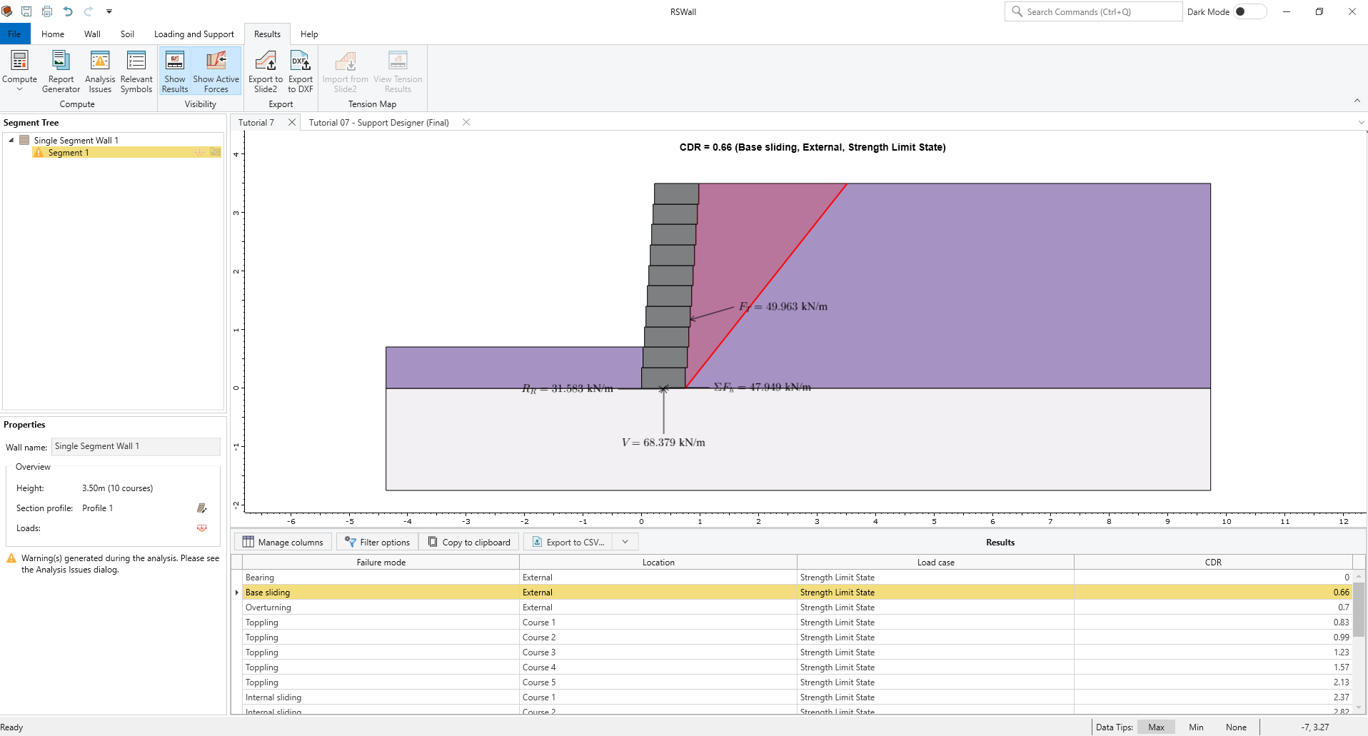
- Select Results > Results > Compute
Based on the result, as expected, this block wall is unstable without reinforcements. Now, we will try to come up with a reinforcement layout with the Support Designer.
5.0 Simply Optimized Layout
- Go to Loading and Support > Designer > Support Designer.
Enable Override default factor of safety and set to 1.2.
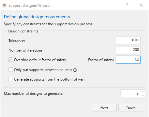
- Click Next.
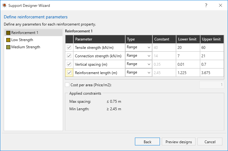
- Set reinforcement parameters for Reinforcement 1:
- Turn ON Tensile strength and set Range to 20-60 kN/m
- Turn ON Connection strength and set Range to 7-21 kN/m
- Turn ON Vertical spacing and set Range to 0.01-0.7m
- Turn ON Reinforcement length and set Range to 1.225-3.675m
The ranges set for the lower and upper limit in the support designer are important. By default, these values are set to:
- Tensile strength: Existing value of selected reinforcement +/- 50%
- Connection strength: Existing value of selected reinforcement +/- 50%
- Vertical spacing: Largest block height of current wall segment +/- 100%
- Reinforcement length: 0.7 * height of current wall segment +/- 50%
Note that spacing is a larger range to provide greater flexibility during optimization
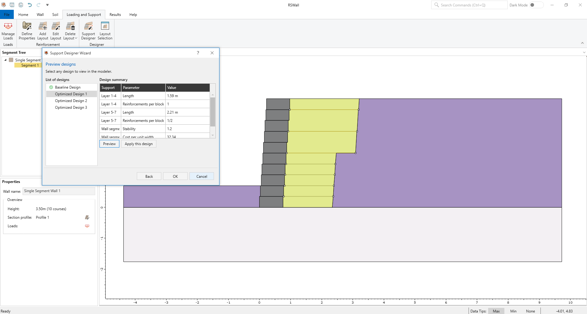
Click Preview designs to start optimization. Once it is completed, the Preview designs dialog will appear.
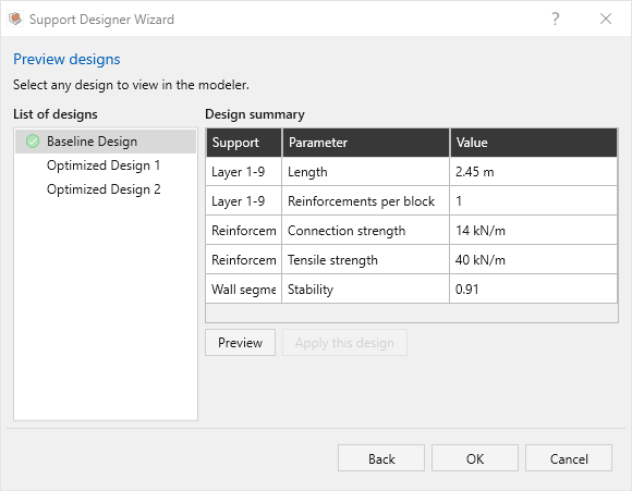
- Select the Baseline design and click Preview. This layout is automatically generated in this case as there was no initial layout. We can see that the stability is less than the target because this design is not optimized (0.91), rather it’s the starting point for optimization.
- Review the Optimized Design 1 and Optimized Design 2 by selecting the designs from the list and clicking on Preview.
We can see that the Design 2 has more reinforcements but shorter and lower connection strength for a similar stability to Design 1.
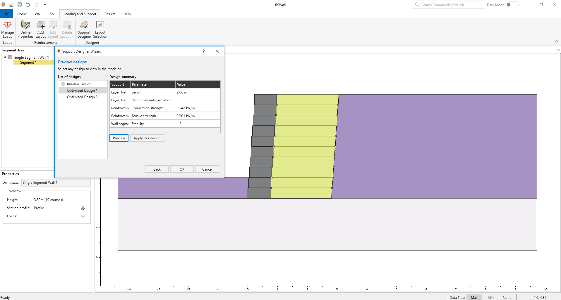

- Select Optimized Design 1 and click Apply this design. Click OK.
This is only a simple example using 1 reinforcement type and the default values of the program. The Support Designer can generate optimized layouts with more complex considerations. We will next run the optimization again but with a more coherent starting point, which should improve the output.
6.0 Further Optimized Layout
- Go to Loading and Support > Reinforcement > Edit Layout
 .
. - We have the two additional reinforcements that we defined previously: Low strength and Medium strength. Of the 9 reinforcements in our current layout, set the 4 with the lowest elevation to Medium strength and the 5 with the highest elevation to Low strength.
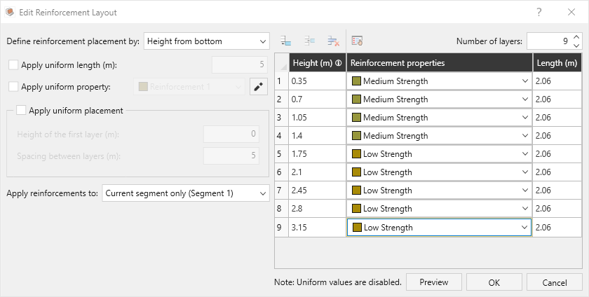
- Click OK to close the dialog.
- Return to the Support Designer dialog (select Loading and Support > Designer > Support Designer). Click Next:
For Low strength, toggle OFF Tensile strength and Connection strength. Toggle ON Vertical spacing and Reinforcement length. Set Cost per area to 2.
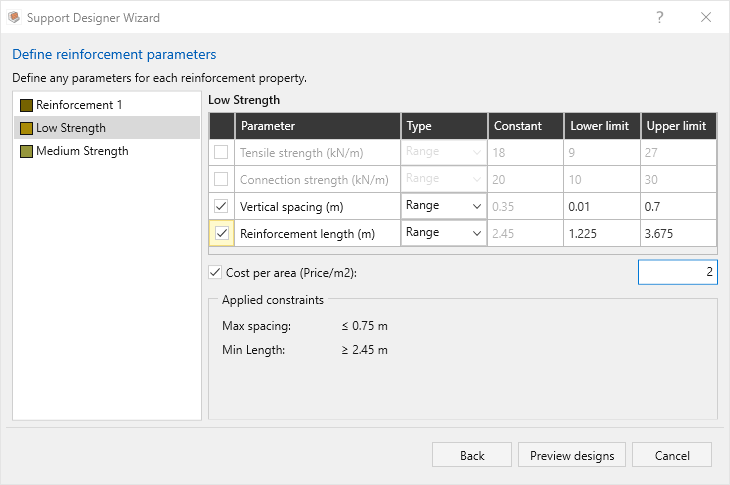
For Medium strength, toggle OFF Tensile strength and Connection strength. Toggle ON Vertical spacing and Reinforcement length. Set Cost per area to 3.
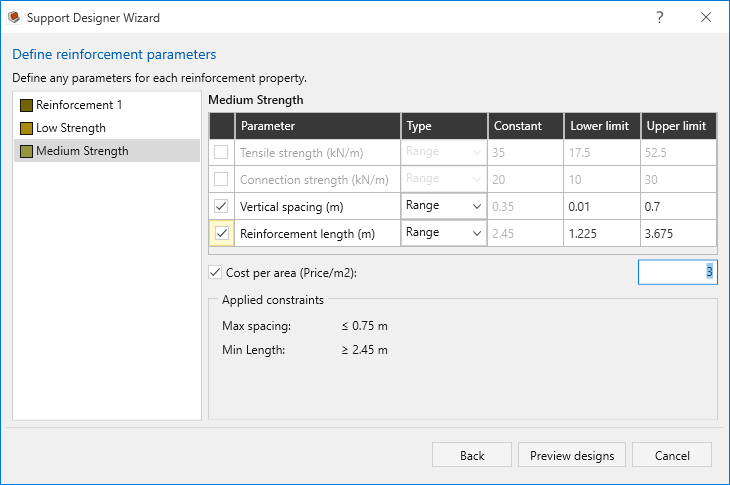
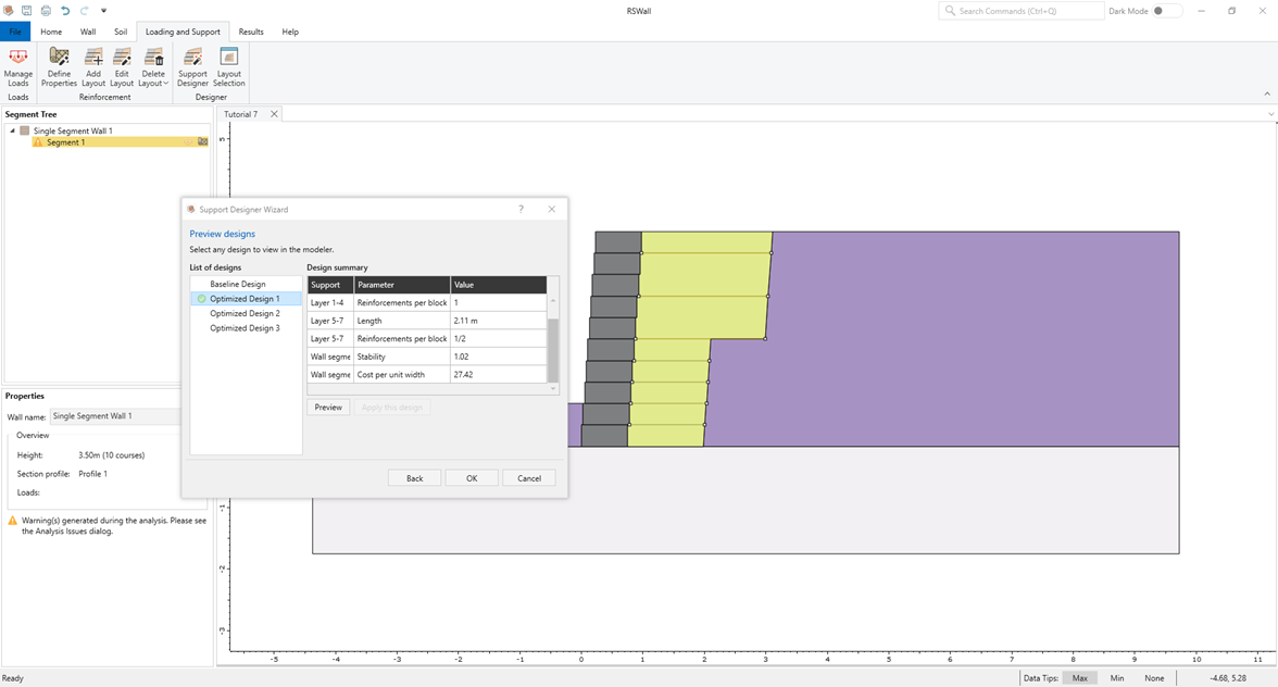
- Click Preview designs to optimize. Now that we have defined a cost per area for each of the reinforcements present in our design, we see a new entry of Cost per unit width in the design summary table.
The new baseline design is the same one which we applied after the previous optimization step (in section 3), and we have generated 3 new design alternatives.
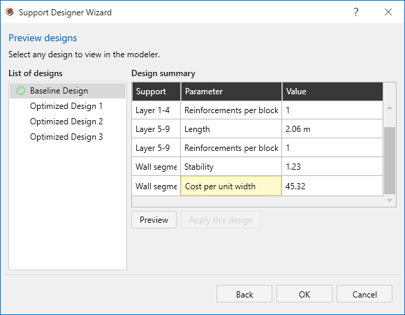
We can see that the cost per unit width of Optimized Design 1 (29.94) is less than Baseline Design (42.68) while still achieving our stability target:
- Apply the Optimized Design 1 by clicking Apply this design.
- Click OK to close the dialog.
- Select Results > Compute

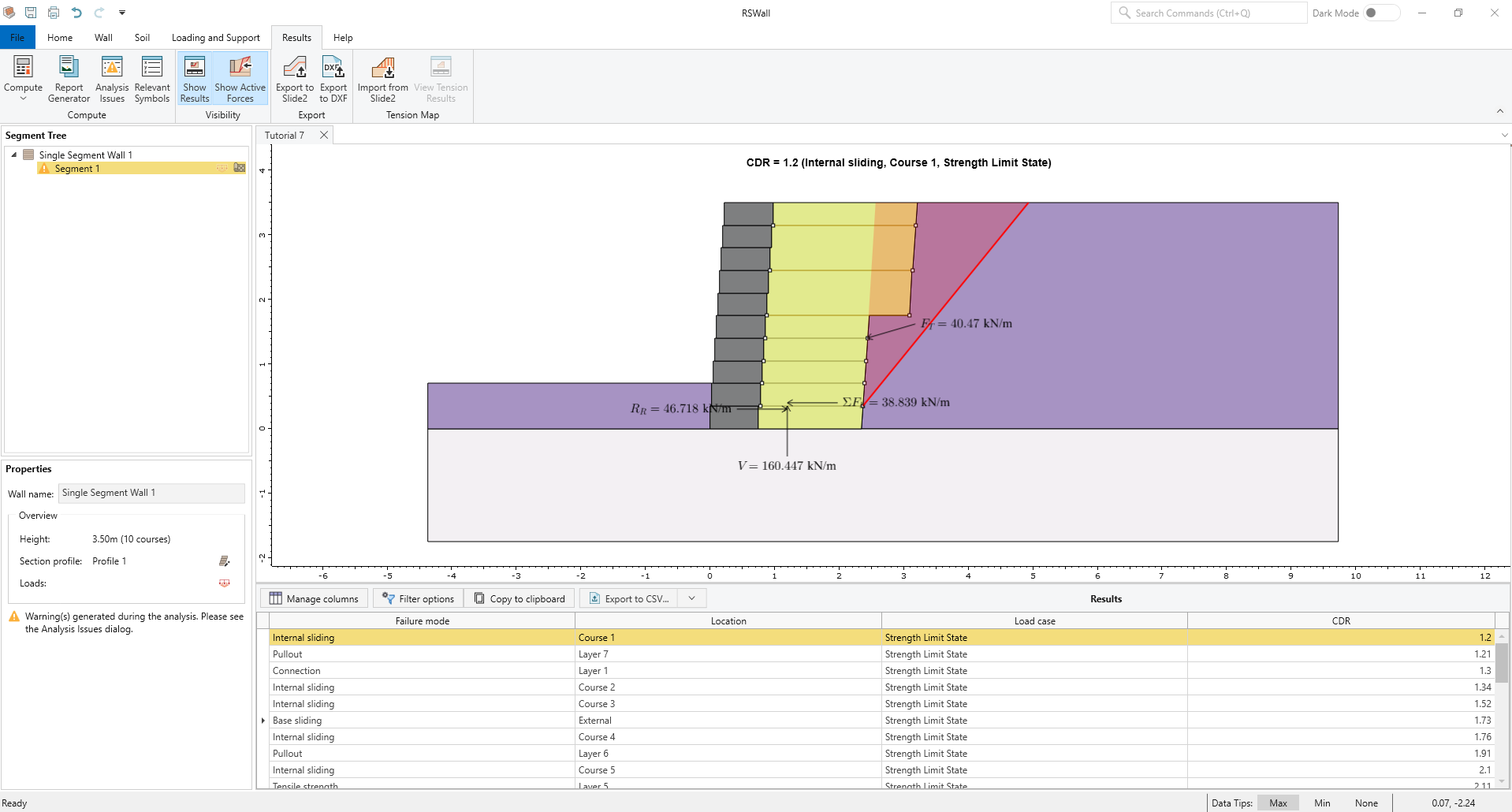
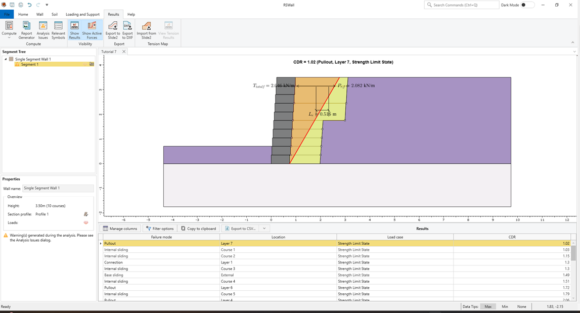
Now we see that, indeed, the minimum CDR is 1.2 for internal sliding at Course 1, but it will be useful to analyze the global stability of this design in Slide2.
7.0 Slide2 Overall Stability Analysis
This section will cover exporting the RSWall project to Slide2 and conducting a stability analysis.
- Select Results > Export > Export to Slide2

- Tick the check box for Segment 1.
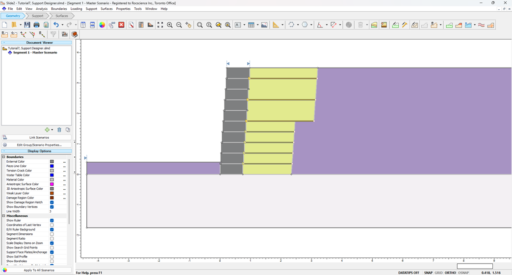
- Click Open in Slide2 to launch the Slide2 program.
Save the Slide2 file as "Tutorial7, Support Designer".
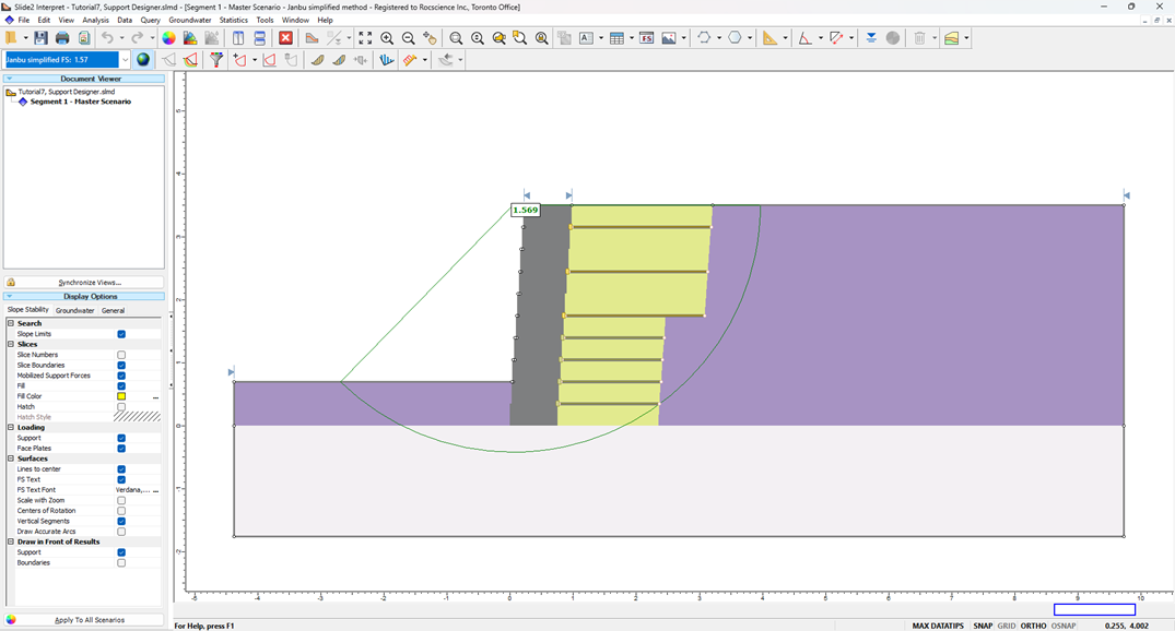
- Select Analysis > Compute.
Once the file is computed, select Analysis > Interpret. Even with conservative Janbu results the FOS is nearly 1.7, while Bishop method gives us more than 2. This indicates that our target stability of 1.2 in RSWall was overly conservative and can be reduced.
- Return to RSWall. Go to Loading and Support > Designer > Support Designer.
Next to Override default factor of safety, set the Factor of safety value to 1.0.
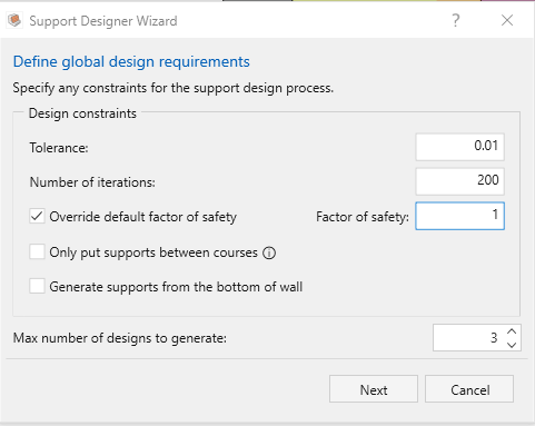
- Click Next, then Preview designs to optimize.
Select Optimized Design 1. As before, the Optimized Design 1 has a lower cost per unit width than the Baseline Design.
- Click on Apply this Design and then OK.
- Select Results > Compute to inspect the least stable failure modes.
As an additional exercise, bring the results back to Slide2, to re-verify the global stability of the design.