4 - RocTopple Export to RS2
1.0 Introduction
In this tutorial, we’ll demonstrate RocTopple’s Export to RS2 option and subsequently how to set up a block toppling model in RS2. RS2 is a finite element stress analysis software. With joint network implementation, RS2 can also predict the failure mechanism and shear strength reduction factor for jointed rock mass.
Topics Covered in this Tutorial:
- Export to RS2
- Model Setup in RS2
- Initial Stresses
- Boundary Conditions
- Mesh Sensitivity and Custom Meshing
- Material and Joint Properties
- Shear Strength Reduction Factor
- Model Interpretation in RS2
Finished Product:
The finished product of this tutorial can be found in the Tutorial 4 Export to RS2.rtop file, located in the Examples > Tutorials folder in your RocTopple installation folder.
2.0 Creating a New File
- Start RocTopple by selecting Programs > Rocscience > RocTopple > RocTopple from the Windows Start menu.
RocTopple automatically opens a new blank document, which allows you to begin creating a model immediately. If the RocTopple application window is not already maximized, maximize it now so the full screen space is available for use.
If you do NOT see a model on your screen:
- Select: File > New

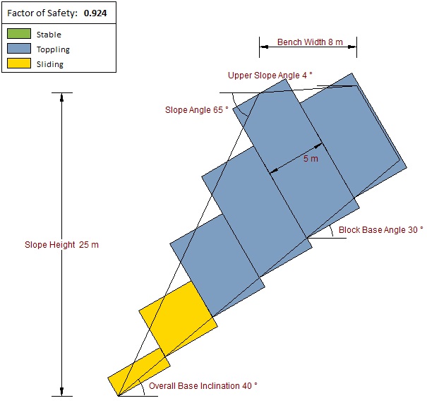
Whenever a new file is created, the default input data will form valid slope geometry, as shown in the figure below:
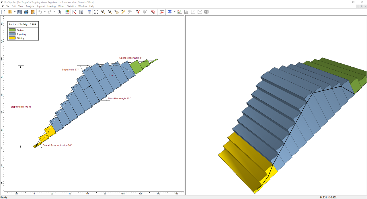
Notice the split screen format of the display. The 2D View shows the slope geometry and the factor of safety, while the 3D View is interactive. Note that the computation is for two-dimensional geometry and assumes unit depth.
3.0 Model
3.1 PROJECT SETTINGS
The Project Settings dialog allows you to configure the main analysis parameters for your model. To open the dialog:
- Select: Analysis > Project Settings

- Keep the default settings.
- Select the Design Standard tab.
- Make sure Design Standard = None.
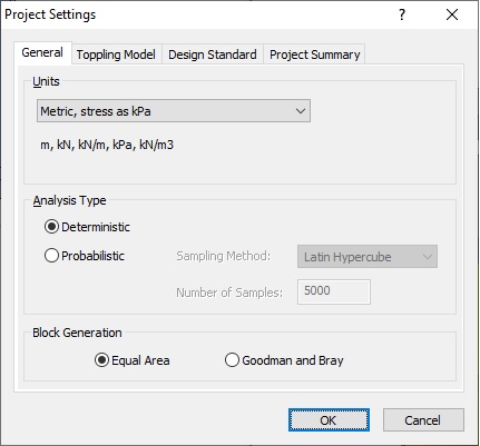
- Click OK.
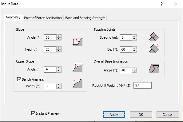
3.2 INPUT DATA
Next, we'll enter input data for the model through the Input Data dialog. To open the dialog:
- Select: Analysis > Input Data

- In the Geometry tab, enter the following data:
Slope
- Angle (degree) = 65
- Height (m) = 25
Upper Slope
- Angle (degree) = 4
- Bench Analysis = YES
- Width (m) = 8
Toppling Joints
- Spacing (m) = 5
- Dip (degree) = 60
Overall Base Inclination
- Angle (degree) = 40
- Rock Unit Weight (kN/m3) = 27
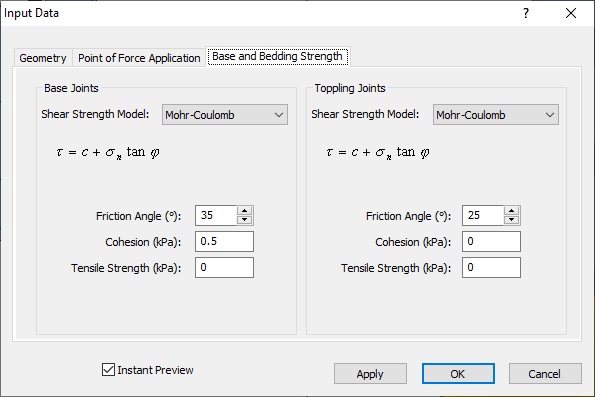
Base Joints
- Shear Strength Model = Mohr-Coulomb
- Friction Angle (degree) = 35
- Cohesion (kPa) = 0.5
- Tensile Strength (kPa) = 0
Toppling Joints
- Shear Strength Model = Mohr-Coulomb
- Friction Angle (degree) = 25
- Cohesion (kPa) = 0
- Tensile Strength (kPa) = 0
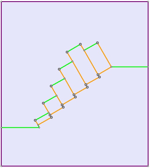
As shown in the figure below, the Factor of Safety is 0.924. At the point of failure, blocks 1-2 are sliding, while all blocks above are toppling.
4.0 Export to RS2
Now we'll export the model to RS2 using the Export DXF File to RS2 option.
4.1 EXPORT DXF FILE
- Select File > Export > Export DXF File to RS2.
- In the Save As dialog, save the DXF file anywhere you like.
4.2. IMPORT DXF FILE INTO RS2
- Start RS2 by double-clicking the RS2
 icon on your desktop.
 - In RS2, select File > Import > Import DXF
 and import the file you exported above.
A DXF Options dialog appears.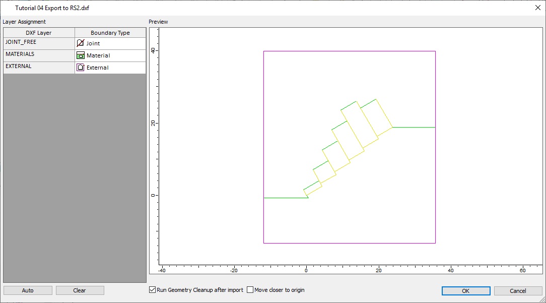
- Assign the appropriate Boundary Type to the corresponding DXF Layer if the program hasn't already done so.
NOTE: If your RocTopple model contains a phreatic surface, make sure it is assigned to the Piezo Line Boundary Type. - Make sure the Run Geometry Cleanup after import check box is selected.
- Click OK.
A Geometry Cleanup dialog appears.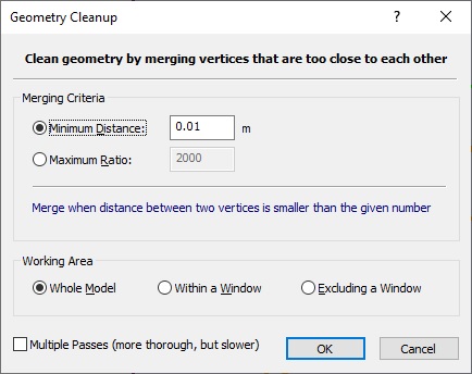
- Keep the default settings and click OK.
A warning dialog appears informing you of the results of the import and cleanup.
- Click OK.
The following model should appear.
5.0 RS2 Model
Before we can compute the model in RS2, we need to excavate it, mesh it, define boundary conditions and initial loading conditions, and define the material and joint properties.
5.1 UNITS
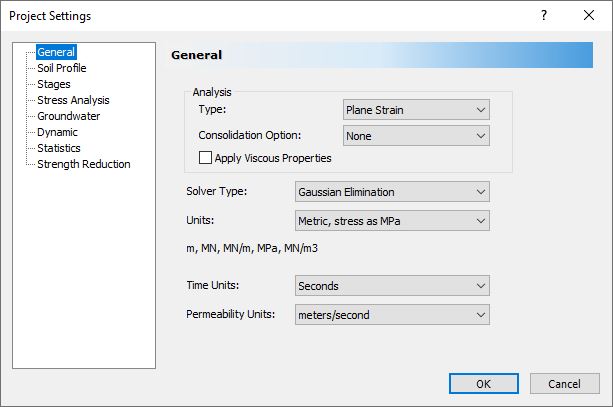
First we'll change the units through the Project Settings dialog. To open the dialog:
- Select: Analysis > Project Settings
- In the General tab, set the Units to Metric, stress as MPa.
5.2 SHEAR STRENGTH REDUCTION FACTOR
We also need to set up the shear strength reduction factor search in Project Settings. We want to find a shear strength reduction factor (SRF or factor of safety) and the slope failure mechanism to compare with RocTopple results.
- Select the Stress Analysis tab and make the following changes:
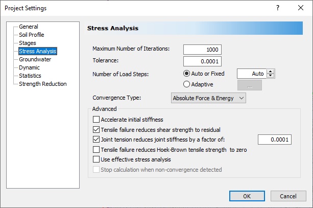
- Select the Strength Reduction tab.
- Select the Determine Strength Reduction Factor check box.
- Change the Initial Estimate of SRF to 0.5.NOTE: Keep in mind that the SRF search will produce a displacement versus shear strength reduction factor graph. Since RocTopple estimated a Factor of Safety of around 0.9, we want to start our RS2 estimate below and away from that value. This way we can generate a more comprehensive graph that shows displacement values for a wider range of SRF.
- Click the Advanced button.
- In the Advanced SSR Settings dialog, make sure you have the following values:
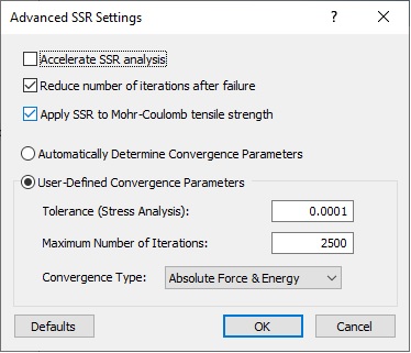 NOTE: The values for Tolerance and Maximum Number of Iterations vary with the model. The user is highly encouraged to try different number of iterations and different tolerances depending on the needs of each model.
 - Click OK in the Advanced SSR Settings dialog.
- Click OK in the Project Settings dialog.
5.3 EXCAVATION
To excavate the model:
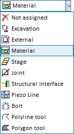
- Right-click on the purple area above the blocks and select Assign Material in the popup menu.
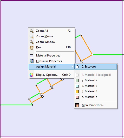
- Select 0. Excavate.
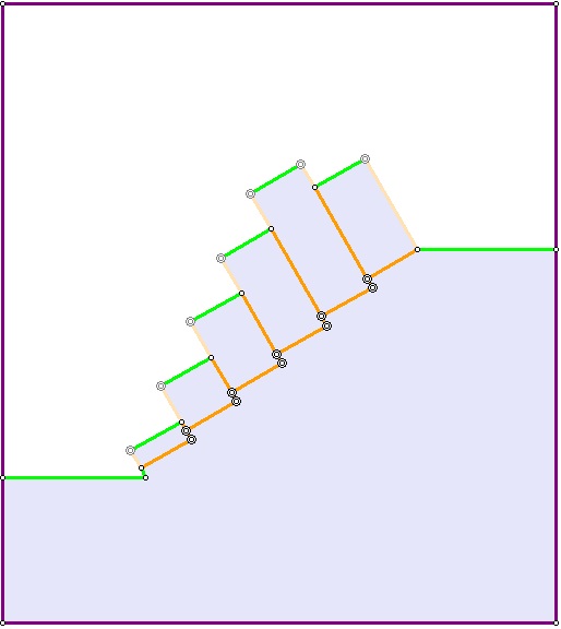
You should see the slope as follows.
5.4 CUSTOM MESHING
Let’s add a mesh to the slope. We’re going to use a custom mesh so that we will have more control over the number of elements. This is highly recommended for models with joint networks because slope stability problems with failure through joints are highly sensitive to the mesh. For models where joints are susceptible to failure, there should be several elements discretized along each joint. Where the mesh is very coarse, the user should be wary of incorrect results (wrong failure mechanism and incorrect Factor of Safety).
To add the mesh:
- Select Mesh Setup
 on the toolbar or the Mesh menu.
The Mesh Setup dialog appears. - Set Mesh Type to Graded.
- Make sure Element Type is set to 6 Noded Triangles.
- Click the Advanced button on the bottom-left corner of the dialog.
- Select the Use Advanced Mesh Regions check box.
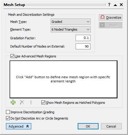
- Click the Add button to add a custom mesh region.
The cursor should change to a cross. - Click in the toe block of the model to highlight it.
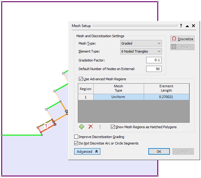
- Back in the Mesh Setup dialog, add custom mesh regions for each block in the model, clicking the Add button and left-clicking in each block until six blocks are highlighted.
The Mesh Setup dialog should now have six custom mesh regions.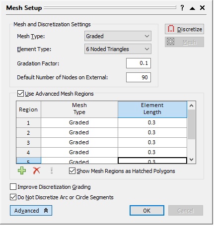
- For each region, change the Mesh Type to Graded and set Element Length = 0.3.
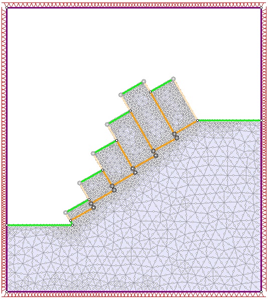
- To discretize the model, click the Discretize
 button in the upper-right corner of the Mesh Setup Dialog.
 - Click the Mesh
 button that appears below.
 - Click OK to close the Mesh Setup dialog.
After meshing is complete, you should note that all the external boundaries are pinned (restrained in x and y), as shown in the figure below.
5.5 BOUNDARY CONDITIONS
Now let’s change the model's boundary conditions. We need to free the top, upper-left and upper-right external boundaries.
- Select Displacements > Free

The cursor should change to a square. - Click to select the top, upper-left, and upper-right external boundaries, and press ENTER.
We also need to apply rollers to the remaining three boundaries. This consists of restraining the x-direction for the bottom-left and bottom-right boundaries, and restraining the y-direction of the bottom boundary.
- Select Displacements > Restrain X

- Click to select the bottom-left and right boundaries, and press ENTER.
- Select Displacements > Restrain Y

- Click to select the bottom boundary and press ENTER.
Finally, we should pin the bottom-left and bottom-right corners.
- Select Displacements > Selection Mode > Pick By Boundary Nodes.
The default is Pick By Segments, which is why we didn't change this setting for the previous boundaries.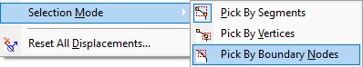
- Select Displacements > Restrain X,Y

- Click to select the two bottom corners and press ENTER.
The model should now look like the following:
5.6 MATERIAL PROPERTIES
Now we need to assign the RS2 model material properties comparable to the rigid body model in RocTopple. We do this through the Define Material Properties dialog. To open the dialog:
- Select: Properties > Define Materials

Notice that the slope is light purple. This is because, by default, it was assigned Material 1 when the model was imported. You’ll also see that the current material property on display in the dialog is Material 1, so let’s edit this material.
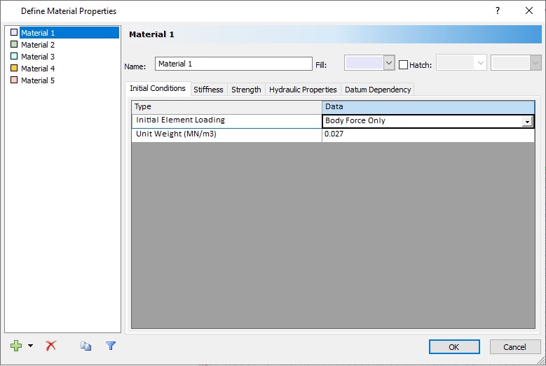
- In the Initial Conditions tab, set Initial Element Loading = Body Force Only.
The reason is that the material weight is the most influential factor on the stresses in the model. - Select the Stiffness tab and set Young’s Modulus (MPa) = 80,000.
- Select the Strength tab and set Material Type = Elastic.
This is because we want to prevent failure through the material (rigid blocks). - Click OK to save the changes and close the dialog.
5.7 JOINT PROPERTIES
Similar to material properties, joints are assigned default properties when imported. In this case, the property assigned to all joints is Joint 1.
TIP: Mouse over any joint in the model to view the property assigned to it. Make sure MIN DATATIPS in the bottom-right corner if the applications window is turned on.
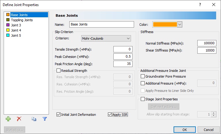
Remember that in RocTopple we set different properties for the Base Joints and Toppling Joints, so we need to define two joint properties. We do this through the Define Joint Properties dialog. To open the dialog:
- Select Properties > Define Joints

The currently selected joint is Joint 1. - Change the name to Base Joints.
- Make the following changes to the properties:
Slip Criterion
- Criterion = Mohr-Coulomb
- Tensile Strength (+MPa) = 0
- Peak Cohesion (+MPa) = 0.5
- Peak Friction Angle (deg) = 35
- Initial Joint Deformation = YES
- Apply SSR = YES
Stiffness
- Normal Stiffness (MPa/m) = 100000
- Shear Stiffness (MPa/m) = 10000
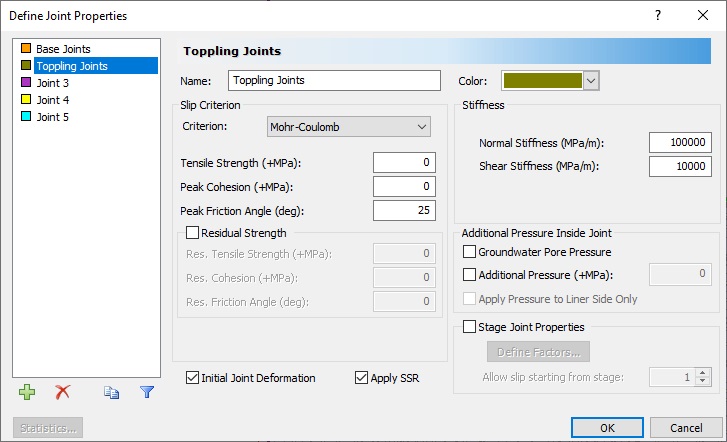
Slip Criterion
- Criterion = Mohr-Coulomb
- Tensile Strength (+MPa) = 0
- Peak Cohesion (+MPa) = 0
- Peak Friction Angle (deg) = 25
- Initial Joint Deformation = YES
- Apply SSR = YES
Stiffness
- Normal Stiffness (MPa/m) = 100000
- Shear Stiffness (MPa/m) = 10000
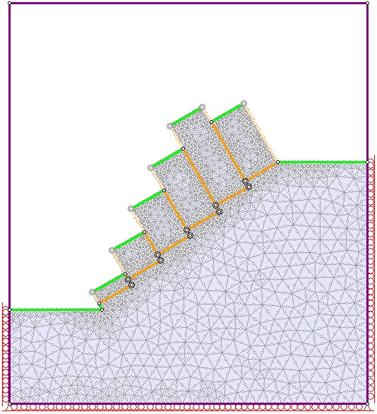
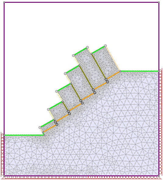
Now let's assign the two properties to the joints on the model.
- Select Properties > Assign Properties

The Assign dialog appears. - Select Joints in the What to assign drop-down list.
You should see a list of all the defined joint properties.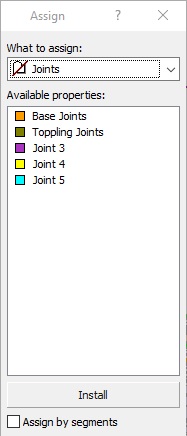
- Click Toppling Joints.
The cursor should to change to a square. - Left-click on all the toppling joints to select and highlight them, and press ENTER.
- Click the X in the top-right corner of the Assign dialog to close it.
The model should now look like the figure below.
We are now ready to compute. Make sure to save the model first.
6.0 Compute
We're now ready to compute the model. Save the model first.
- Select: Analysis > Compute

7.0 Results
We can now view the results in RS2 Interpret.
- Select: Analysis > Interpret

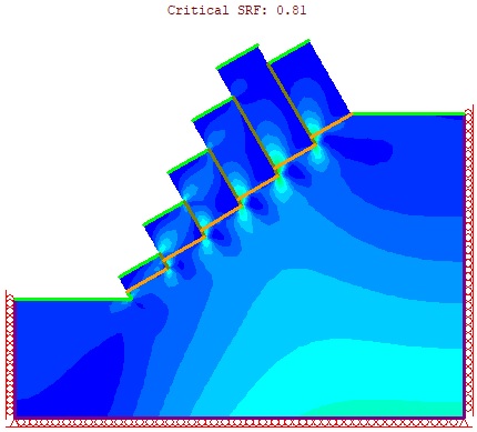
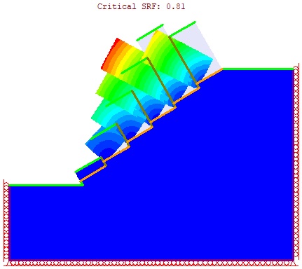
You should see the critical Shear Strength Reduction Factor (SRF) as 0.81 and the maximum shear strain occurring at the bottom-left corners of blocks, as shown in the figure below.
Before looking at any other result, you should always check that the Displacement versus SRF graph gives an acceptable inverted “L” shape.
To generate the graph:
- Select: Graph > Graph Shear Strength Reduction
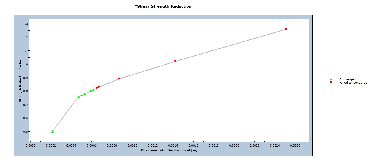
This graph indicates that the maximum total displacement increases as the SRF increases (joint shear strength decreases). Once failure occurs, the displacement takes off.
- Close the graph.
Now let’s look at the displacement contours.
- In the drop-down list that currently shows Maximum Shear Strain, select Solid Displacement > Total Displacement.
TIP: You can also see the deformed shape by clicking Display Deformation Contours ![]() on the toolbar.
on the toolbar.
You are encouraged to further explore the results. For example, you could look at where the joints have yielded or at the normal and shear stresses in the joints.
In general, we can see that RocTopple and RS2 generated comparable results. RS2 predicted a slightly lower Factor of Safety, 0.81, compared to 0.92 in RocTopple. Both programs predicted that, at the point of failure, Blocks 1 and 2 are sliding critical, while Blocs 3 and 6 are toppling critical.
This concludes the tutorial. You are now ready for the next tutorial, Tutorial 05 - Flexural Toppling in RocTopple.