5 - Block Flexural Toppling
1.0 Introduction
This tutorial introduces you to the Block Flexural Toppling model in RocTopple. The Block Flexural Toppling model is based on the limit equilibrium method of Amini, Majdi, and Veshadi published in 2012 in the paper Stability Analysis of Rock Slopes Against Block-Flexure Toppling Failure.
Topics Covered in this Tutorial:
- Toppling Models
- Point of Application
- Internal Rock Strength
Finished Product:
The finished product of this tutorial can be found in the Tutorial 5 Block Flexure Toppling.rtop file, located in the Examples > Tutorials folder in your RocTopple installation folder.
2.0 Creating a New File
- Start RocTopple by selecting Programs > Rocscience > RocTopple > RocTopple from the Windows Start menu.
RocTopple automatically opens a new blank document, which allows you to begin creating a model immediately. If the RocTopple application window is not already maximized, maximize it now so the full screen space is available for use.
If you do NOT see a model on your screen:
- Select: File > New

Whenever a new file is created, the default input data will form valid slope geometry, as shown in the figure below:
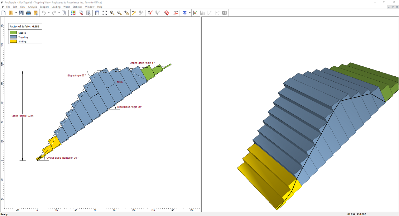
Notice the split screen format of the display. The 2D View shows the slope geometry and the factor of safety, while the 3D View is interactive. Note that the computation is for two-dimensional geometry and assumes unit depth.
3.0 Model
3.1 PROJECT SETTINGS
The Project Settings dialog allows you to configure the main analysis parameters for your model. To open the dialog:
- Select: Analysis > Project Settings

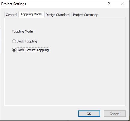
- Select the Toppling Model tab.
You'll see that two Toppling Models are available: Block Toppling and Block Flexural Toppling.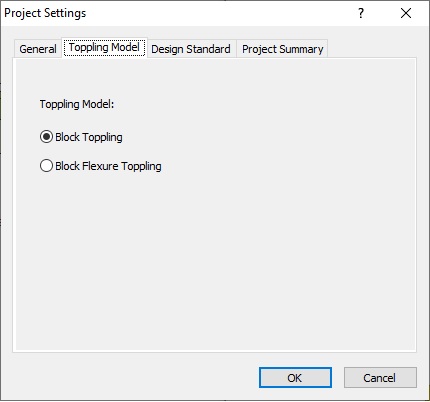
- Keep Block Toppling selected for now. We'll change this later for comparison.
- Click OK to close the dialog.
3.2 INPUT DATA
Now we'll enter input data for the model using the Input Data dialog. To open the dialog:
- Select: Analysis > Input Data

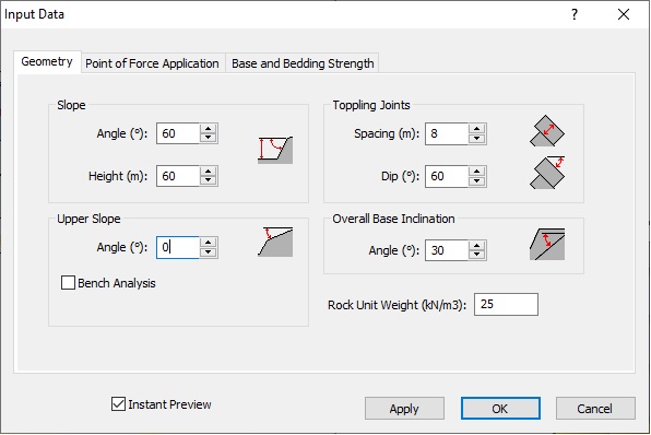
- In the Geometry tab, make changes as follows:
Slope
- Angle (deg) = 60
- Height (m) = 60
Upper Slope - Angle (deg) = 0
Toppling Joints
- Spacing (m) = 8
- Dip (deg) = 60
Overall Base Indication - Angle (deg) = 30
- Rock Unit Weight (kN/m3) = 25
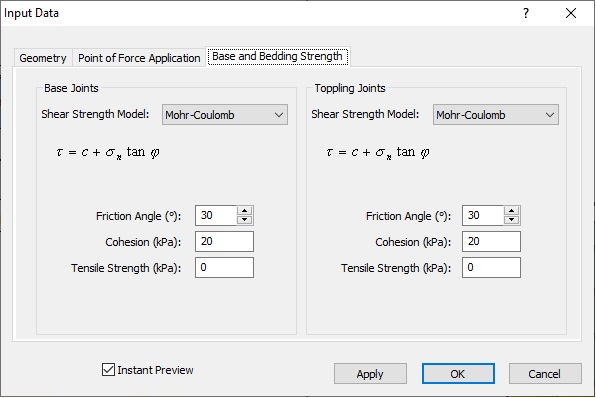
Base Joints
- Shear Strength Model = Mohr-Coulomb
- Friction Angle (deg) = 30
- Cohesion (kPa) = 20
- Tensile Strength (kPa) = 0
Toppling Joints
- Shear Strength Model = Mohr-Coulomb
- Friction Angle (deg) = 30
- Cohesion (kPa) = 20
- Tensile Strength (kPa) = 0
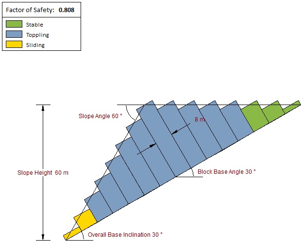
The model should look as in the following figure with a Factor of Safety of 0.808.
4.0 Block Flexure Toppling Model
Now let's select the Block Flexure Toppling model to look at the effects.
4.1 PROJECT SETTINGS
- Re-open the Project Settings dialog.
- Select the Toppling Model tab and select Block Flexure Toppling as the Toppling Model.
- Click OK to save the change and close the dialog.
Note that the Factor of Safety has changed to 0.912.
4.2 INPUT DATA
Next we'll go back and make changes to the input data.
- Re-open the Input Data
 dialog.
Note that there is an added Internal Rock Strength tab to allow for consideration of shear failure due to flexure in each block. - Select the tab and enter the following:
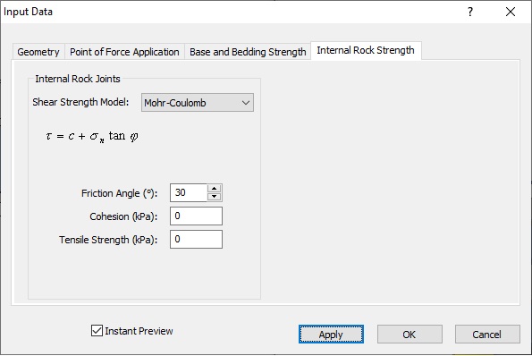
Note that, unlike for the Base Joints and Toppling Joints (in the Base and Bedding Strength tab), only Mohr-Coulomb is available as the Shear Strength Model.- Change the Friction Angle to 30°.
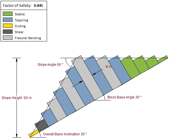
Note that the Factor of Safety has reduced to 0.845. - Select the Geometry tab and note that Overall Base Inclination is disabled.
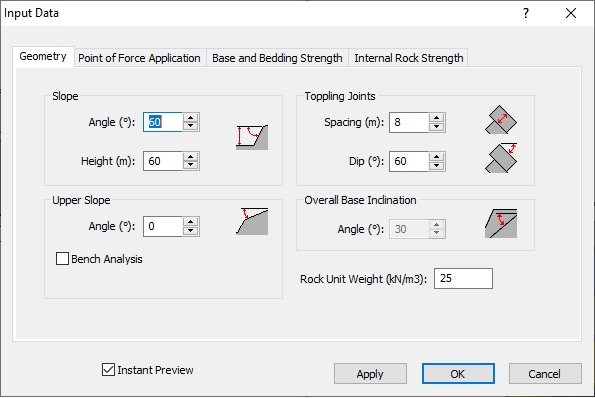
This is because, in the Block Flexural Toppling model, the slope is linear. As a result, Toppling Joints Dip and Overall Base Inclination have a fixed relationship. Therefore, with a Dip of 60°, a 30° Overall Base Inclination is calculated automatically. - Select the Point of Force Application tab.
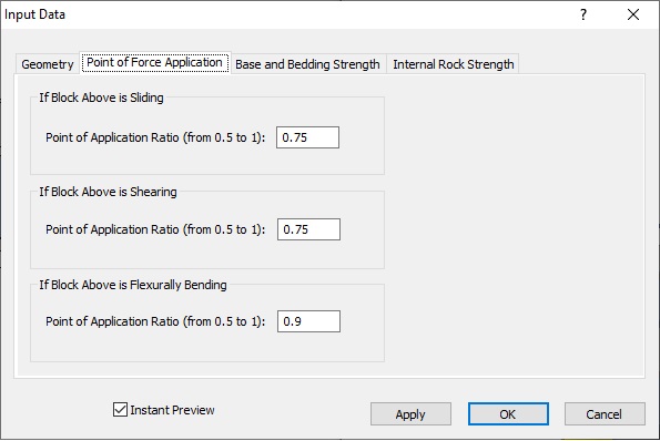
Note that you can enter ratios between 0.5 and 1 for cases when the block above is sliding, shearing, or flexurally bending. These mark where the normal force from the block above is applied on the current block for equilibrium calculations. For more help, see Point of Force Application Input in RocTopple. - Keep the default values.
- Click OK to save changes and close the dialog.
The model looks like the following:
5.0 Analysis Results
As shown in the figure below, the two toppling models yield comparable results.
The first two blocks are sliding (sliding after shearing) critical. The top three blocks are stable. The middle blocks are toppling or flexural toppling. The difference is in the fourth top block (or the 12th block from the toe). In the Block Flexural Toppling model, there is enough shear strength to prevent the block from toppling over, hence the higher Factor of Safety.
This concludes the tutorial.