1 - 3D Model Generation
1.0 Introduction
This tutorial helps you become familiar with the process of reconstructing a 3D model in FragMetriX’s MultiPhoto tool.
MultiPhoto is a convenient tool designed for generating 3D models from multiple overlapping images, typically obtained from aerial photography using Unmanned Aerial Vehicle (UAV) systems. After the user sets all the input parameters, the reconstruction process runs automatically. Additionally, MultiPhoto includes standard and constrained referencing features that references the 3D model to a higher-level coordinate system using externally surveyed Ground Control Points (GCP).
Topics covered in this tutorial
- Data Input and Settings
- Coarse Reconstruction
- Dense Reconstruction
- Exporting the Model
Finished product
The finished product of this tutorial as well as all project materials can be found in the Tutorial 1 - 3D Model Generation.zip folder.
2.0 Generating a new 3d model
MultiPhoto processes the data in a sequential procedure, a so-called processing pipeline. The key steps include the following:
- Coarse Reconstruction determines the camera orientations and positions among all photographs relative to each other and relative to the coarsely reconstructed object. The result of the Coarse Reconstruction is the Project File (*.smm file).
- Region of Interest (ROI) features the definition of a Region of Interest, which limits the generation of the 3D model (Dense Reconstruction) to a selected area. The definition of the ROI is an optional and intermediate step in MultiPhoto, and it has to be outlined on the coarse point cloud after the Coarse Reconstruction.
- Dense Reconstruction calculates the detailed object geometry including a detailed point cloud, surface mesh and texture. The result of the Dense Reconstruction is the 3D model file (*.jm3x file).
- Referencing and/or Scaling referencing using Ground Control Points (GCP) as well as scaling of 3D models in a local co-ordinate system.
If you have not already done so, run the FragMetriX (FMX) program by:
- Double-clicking the FMX icon
 on the desktop, in your installation folder or by selecting Programs > FragMetriX > FragMetriX in the Windows Start menu.
 - When the program starts, select MultiPhoto
 to run the MultiPhoto tool.
Whenever the MultiPhoto tool runs, a default Workflow Selection dialog opens as shown below.
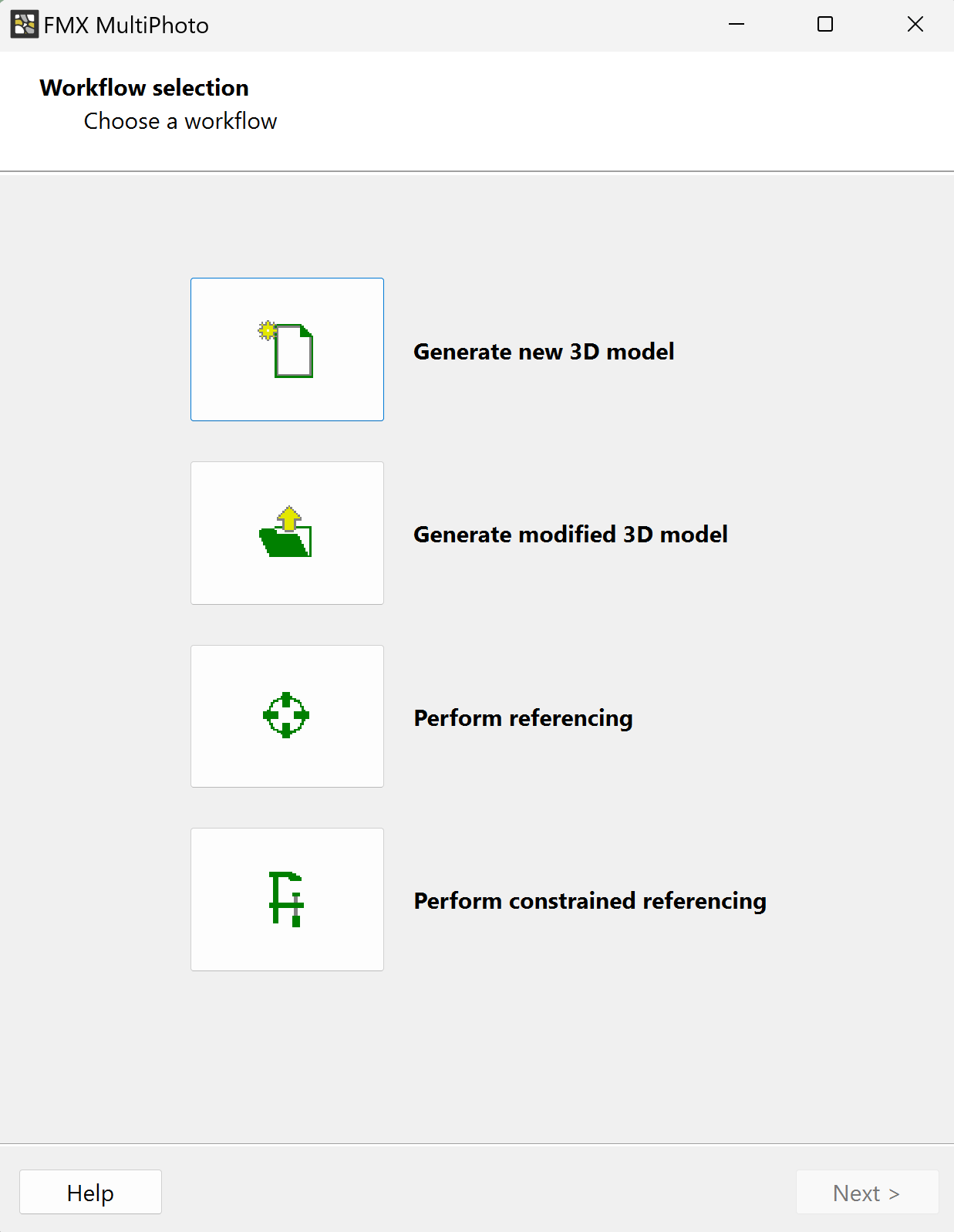
MultiPhoto supports four different workflows that can be selected by the user:
- Generate new 3D model: Load photos, define the co-ordinate system [optional] and perform 3D model reconstruction (coarse and dense reconstruction).
- Generate modified 3D model: Load a project file (*.smm file; coarse reconstruction), modify the settings and perform the 3D model reconstruction (*.jm3x file; dense reconstruction).
- Perform referencing: Load a project file (*.smm file; coarse reconstruction) and 3D model file (*.jm3x file; dense reconstruction), then perform referencing using surveyed Ground Control Points or scale the 3D model.
- Perform constrained referencing: Load a project file (*.smm file; coarse reconstruction), modify the settings, optimize the reconstruction using surveyed Ground Control Points and perform 3D model reconstruction (*.jm3x file; dense reconstruction).
- Select Generate new 3D model

3.0 Data input
FragMetriX comes with several example images and files installed with the program. These example images and files can be accessed through Documentation > Online Resources link in your FragMetriX Documentation  tool. This tutorial will use Image 01-129 files to demonstrate the basic 3D model creation features of FragMetriX.
Configure Project page enables you to load images for processing and set parameters for both Coarse and Dense Reconstruction. Additionally, it allows you to adjust the camera calibration of the photos and visualize the positional information stored in photos.
Field images stored in a folder can be loaded as a series of photos using Load Folder, or individually using the Load Files option. To load images individually:
- Click Load Files

- Select all the images in Images folder.
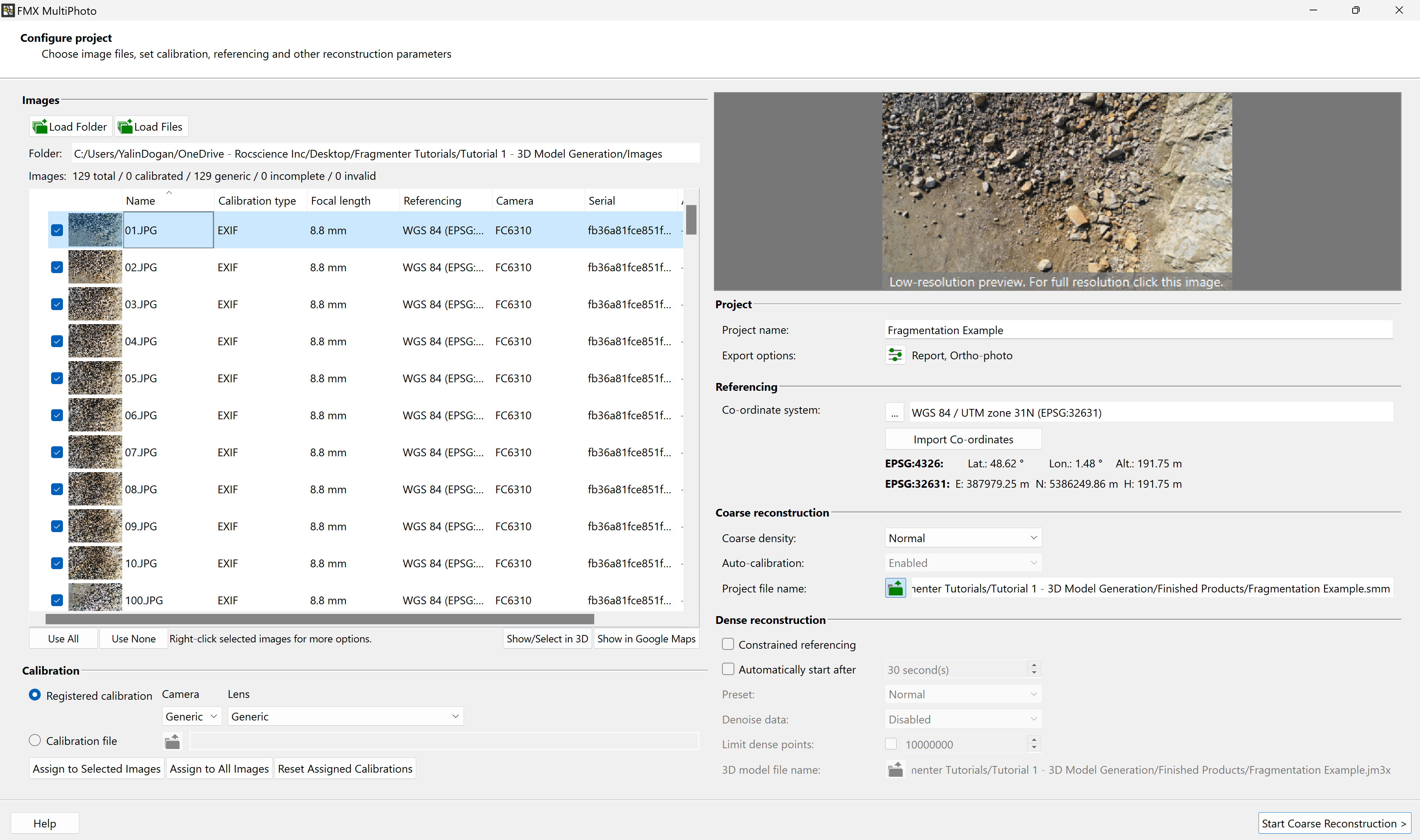
Notice that the list of the loaded images indicates the Picture thumbnail, Name of the image, Calibration type, Focal length, Referencing, Camera, Serial number and additional information for each entry.
You can also view the total, calibrated, generic, incomplete, invalid number of loaded images at the top of the images list. Images to be included or excluded in 3D model generation can always be controlled by checking/unchecking the checkboxes next to each image.
3.1 Calibration
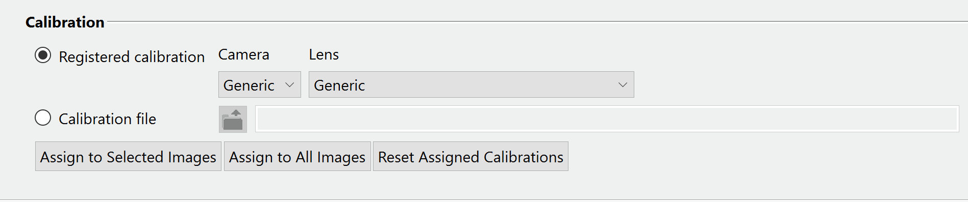
MultiPhoto uses the camera calibration information from the “exif” (extended image information) metadata stored in the camera photos.
Users can install and register calibration data via Start Window > Settings > User Data and use this calibration information or upload an external calibration file (“cam.dat” file) by clicking the Calibration File icon.
3.2 Project Settings
- Go to Project name under the Project settings and enter “Fragmentation Example” as the project name.
- Updating the project name updates the Project File name and the Output File name.
- Export options
 opens a dialog for choosing export options; i.e. the reconstruction report (*.pdf), ortho-photo (*.png), GeoTIFF (*.tif) and *.obj export. Selected exports are generated and saved automatically by the software after closing MultiPhoto. The default export options are Report and Ortho-Photo.

We will proceed with the default export options for this example.
3.3 Referencing
Referencing is an optional tool in MultiPhoto and can be performed only if positional information is available with the images.

The referencing for this example is performed using the positional information of the images obtained from Drone GPS capturing the images. The UTM zone is auto detected from the referencing information of images (WGS 84).
When using drone GPS with normal accuracy, only the scaling information will be accurate, and positioning and orientations may deviate significantly. If the positioning and orientations are important, ground control points (GCP) should be used for referencing.
Users can also select a user defined coordinate system by clicking on the elipses  button and selecting Browse Coordinate System or import GPS coordinates from a “.txt” file. The 3D model will be transferred automatically into the desired coordinate system after 3D model generation.
3.4 Coarse Reconstruction Settings
- The Coarse Density is selected as Normal by default in MultiPhoto.
Normal feature density is used for images with reasonably high overlap. In case you are using images with low overlap or strong angular changes, High feature density should be selected.
Additionally, Auto-calibration is mandatory when using uncalibrated (generic entry) photos. If photos from pre-calibrated cameras are being used (calibration entry), auto-calibration can be either enabled or disabled by the user.

- We will proceed with Normal feature density in this example.
3.5 Dense Reconstruction Settings
Constrained Referencing optimizes the 3D model by using the positions of externally surveyed Ground Control Points (GCPs) to improve spatial accuracy. Initial camera positions are readjusted and optimized, while the generated 3D points of the dense point cloud (3D model) are aligned to the GCP coordinates. Constrained referencing can be enabled and disabled during the Configure Project phase.
Constrained referencing should only be applied when spatial positioning is critical and it is not a standard user procedure for fragmentation analysis.
GCP constrained optimization is an intermediate step in the 3D model reconstruction process and cannot be performed afterward
The Automatically Start After feature can be enabled if the user wants the reconstruction process to continue automatically after a user-defined time from Coarse Reconstruction into Dense Reconstruction. Enabling the Automatically Start After feature also activates the Dense Reconstruction settings (which should be defined in Dense Reconstruction step if automatically start after feature is not enabled).
Automatically Start After is only possible if Standard Referencing is enabled (Constrained Referencing is not enabled).
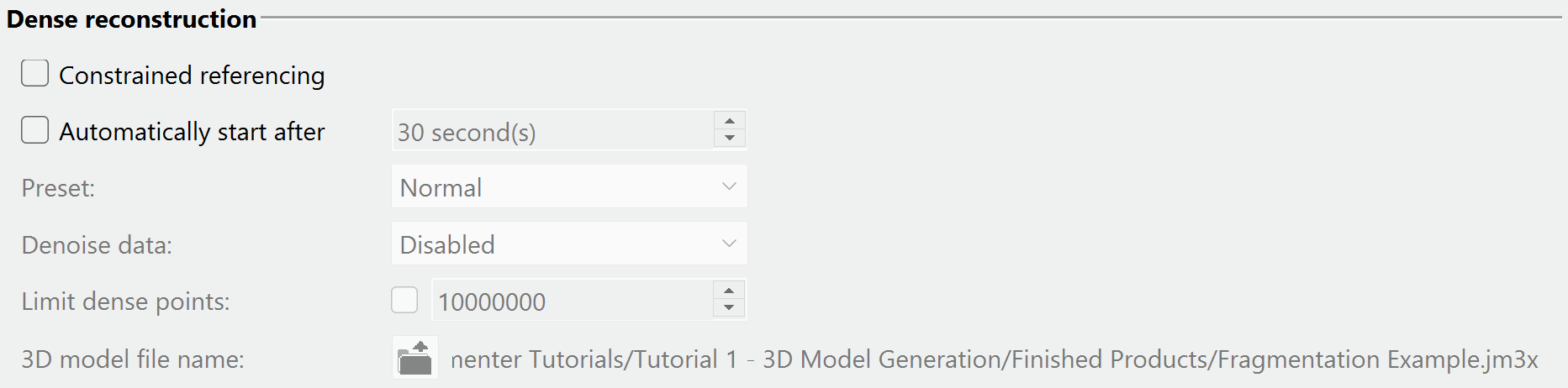
- We will leave dense reconstruction settings as is and proceed with default settings for now for this example.
Click Start Coarse Reconstruction to start the coarse reconstruction process and move to the next step.
4.0 Coarse reconstruction
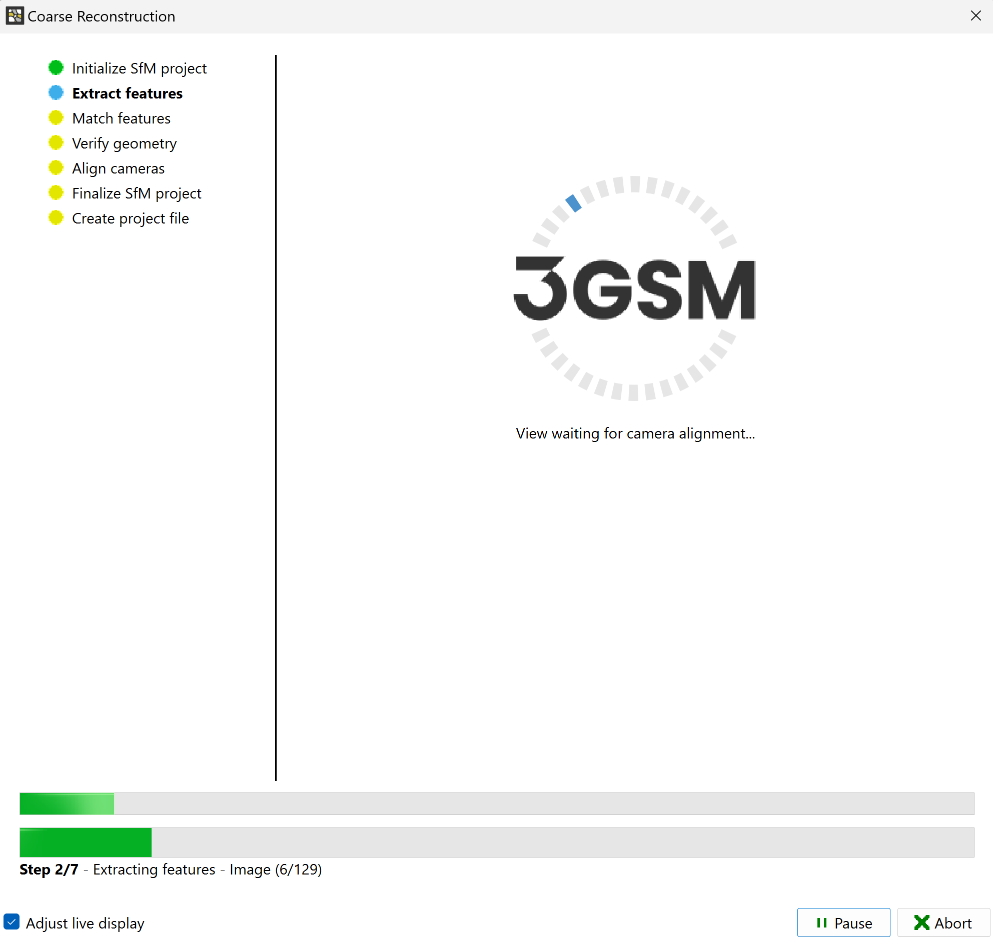
The progress window will appear and reveal the status of the coarse reconstruction including a live display of progress.
A 3D model preview will be available after the coarse reconstruction is completed.
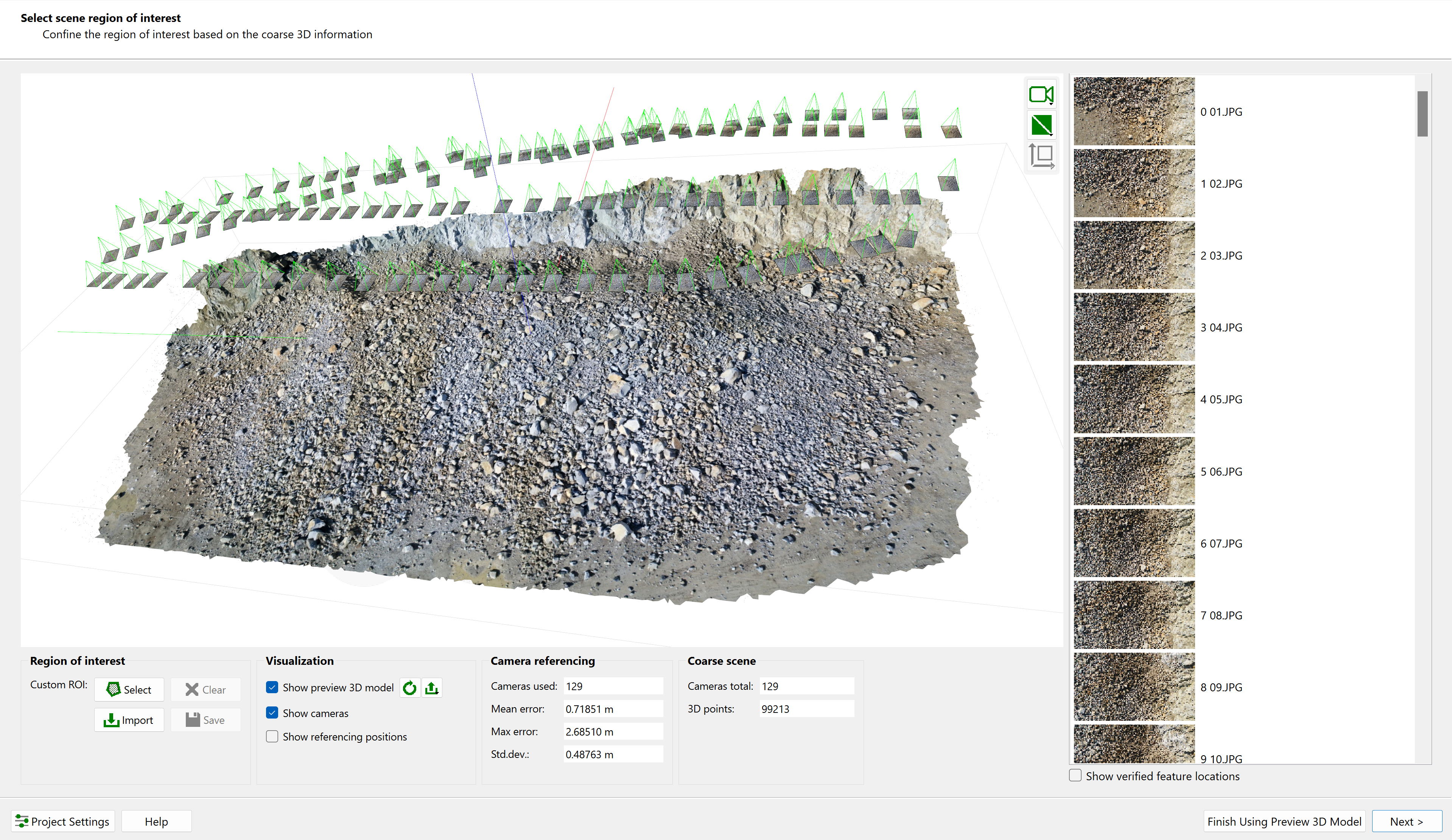
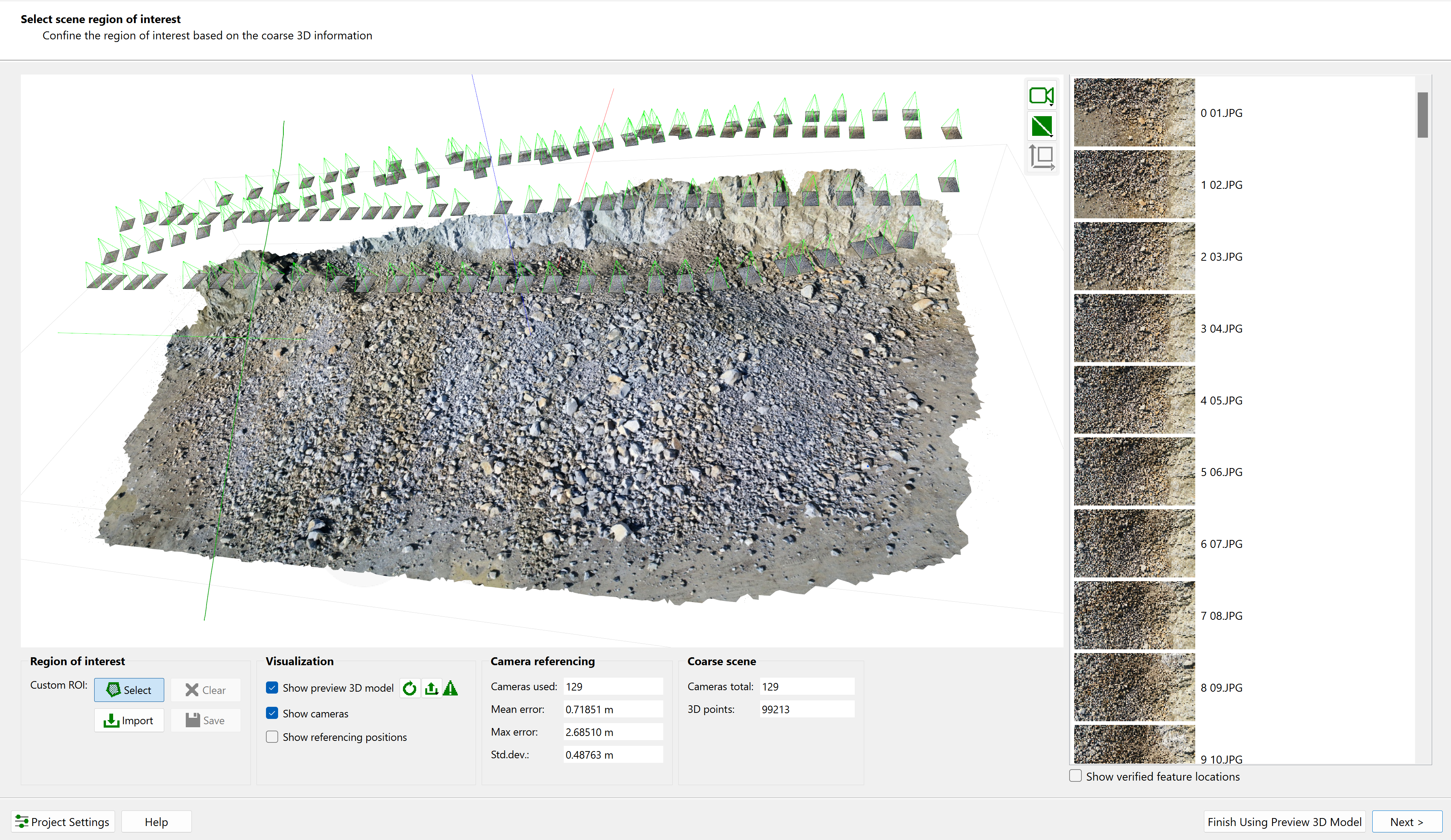
- A Region of Interest (ROI) can also be defined in this step by clicking Select to activate drawing mode in Custom ROI and drawing a polygon.
The definition of the Region of Interest is optional, and it is skipped by clicking the Next button. If no ROI is defined, the entire 3D point cloud of the Coarse Reconstruction is used for Dense Reconstruction.
- Draw a Region of Interest around the muck pile with the mouse while keeping the left mouse button pressed. A green line indicates the boundary of the region of interest. In order to draw a straight line of the polygon, press the left mouse button together with the Shift key. Releasing the Shift key ends the straight line.
Once you release the left mouse button, the preview 3D model is trimmed and shows the areas which will be used for the Dense Reconstruction. If you want to modify the Region of Interest, you can click the Clear button and redraw the region.
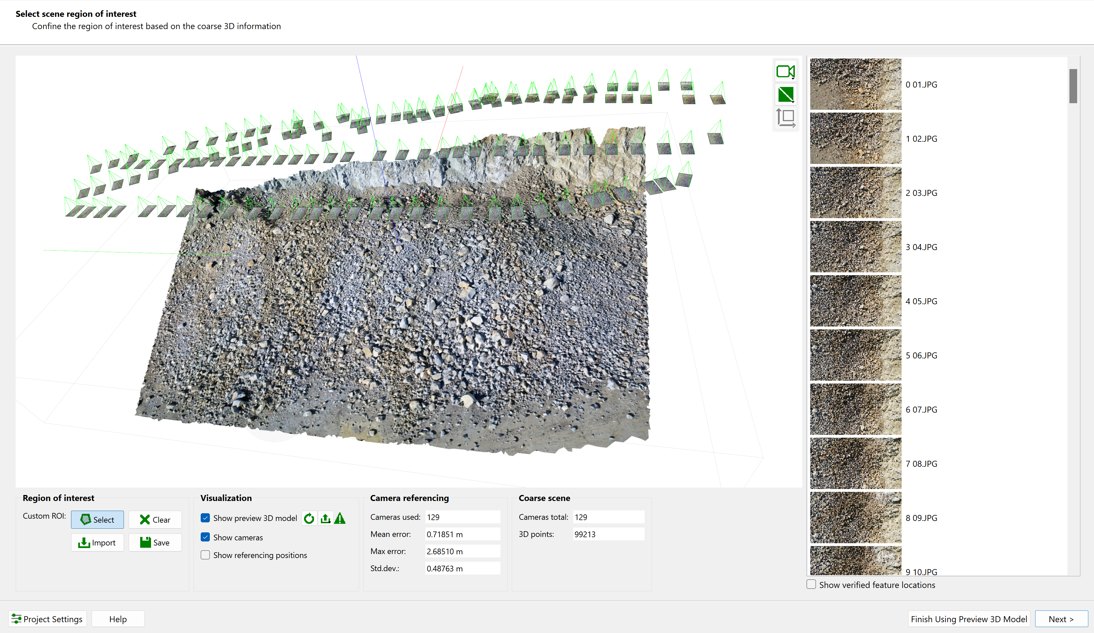
- Click Clear to clear the Region of Interest and then click Next to proceed to Dense Reconstruction.
5.0 Dense reconstruction
Dense Reconstruction calculates the detailed object geometry including a detailed point cloud, surface mesh and texture to compute a dense 3D scene (output file *.jm3x).
There are three different Dense Construction Presets that can be selected by the user:
- Fast dense construction preset generates low resolution topography and low-resolution texture (can be used for volume calculations, etc.).
- Normal dense construction preset is the default preset option and generates medium resolution topography and high-resolution texture (can be used for blast design, single faces and benches for rock mass characterization, etc.).
- High dense construction preset generates high-resolution topography and high-resolution texture (can be used for fragmentation analysis, multi faces and benches for rock mass characterization, etc.).
Enabling or disabling the Denoise Data option controls whether noise suppression will be applied to point cloud.
Limit dense points defines the upper limit for number of points which generates the reconstructed 3D model. The Limit dense points feature is optional and default value is 10.000.000 points.
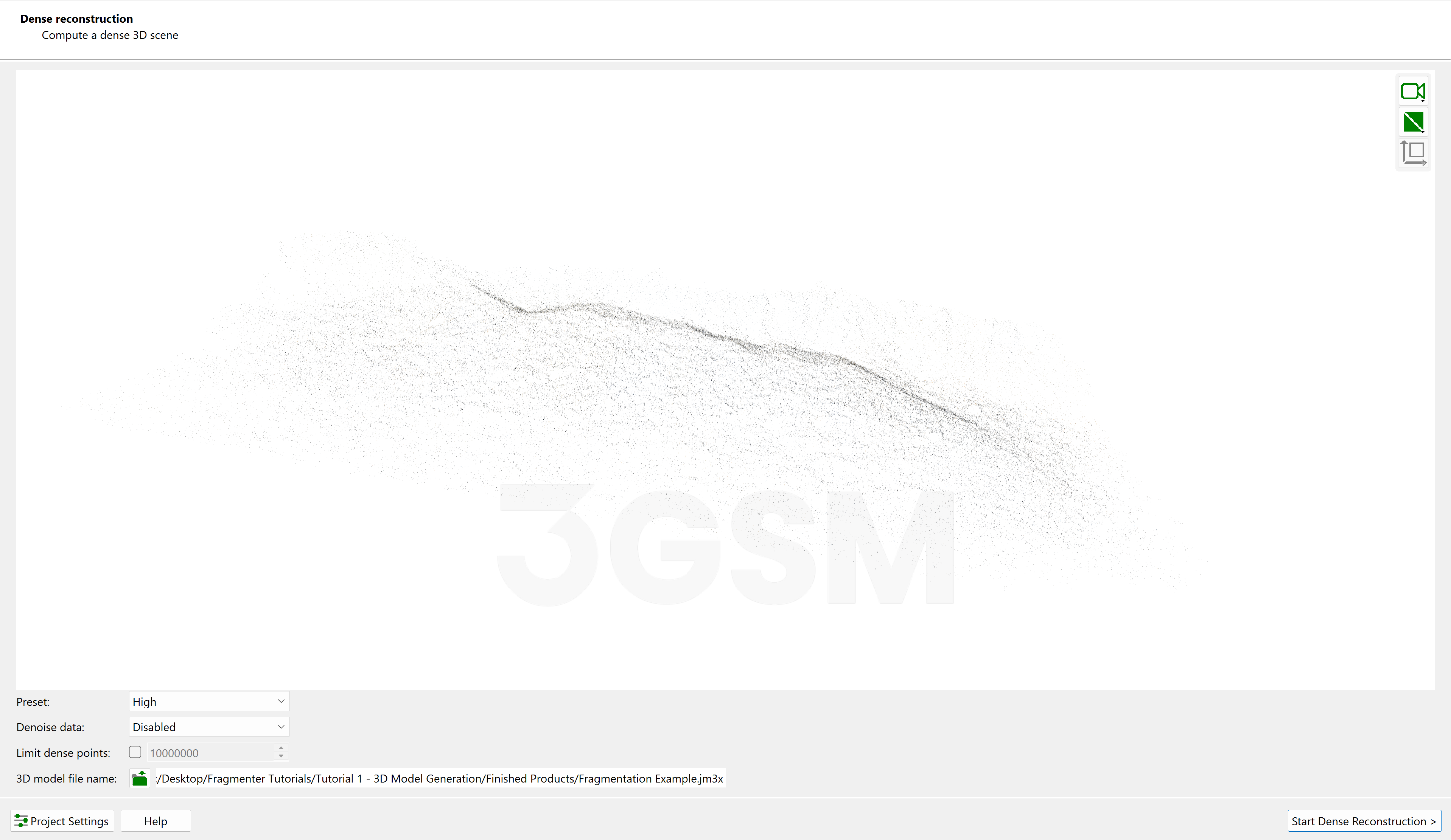
- Select the High preset to generate high-resolution topography and high-resolution texture for fragmentation analysis purposes on a muck pile.
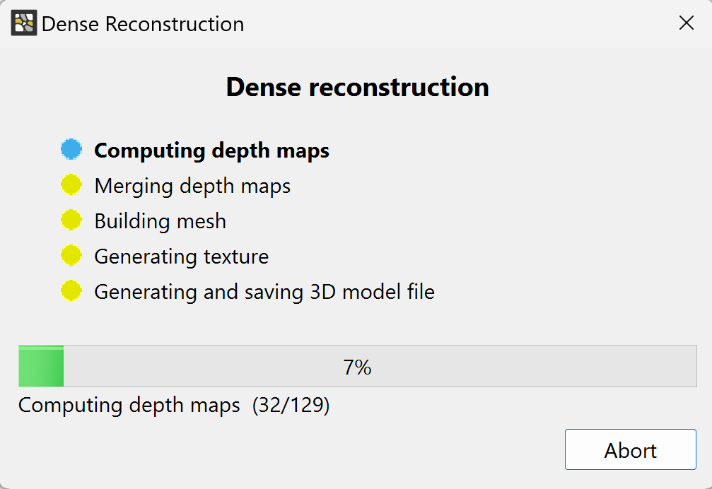
- Click Start Dense Reconstruction to start the dense reconstruction process and move to the next step.
6.0 3d model output and export
Once the Dense Construction process is completed, a 3D model with texture is generated and an output file (*.jm3x) is automatically saved. The resulting 3D model is displayed in the 3D viewer.
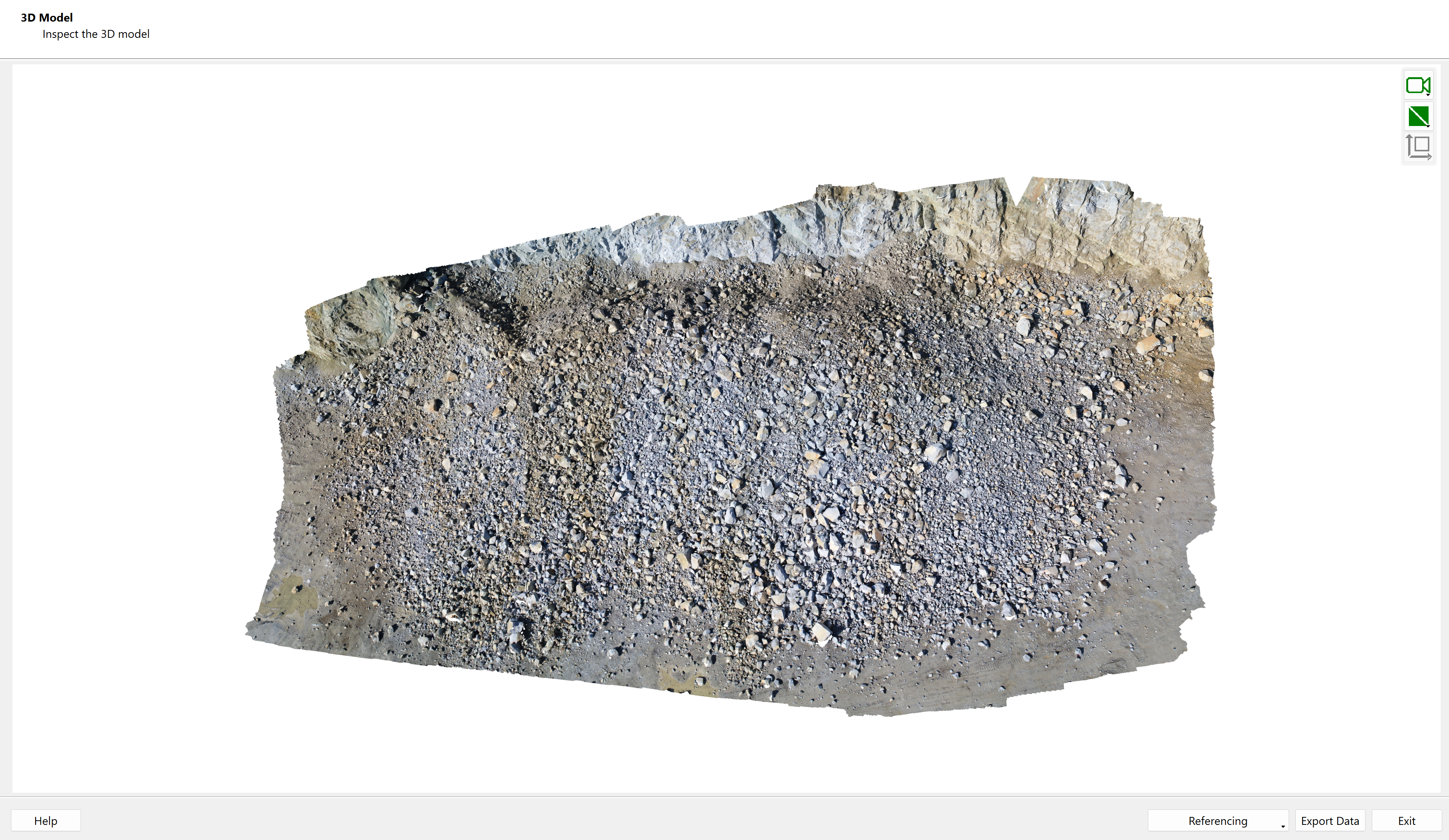
Additional files according to the Project Settings are also generated at this stage. In this example, a PDF report about the reconstruction process and an ortho-photo of the 3D model (*.jpg) are generated.
- You can choose data export options by clicking Export Data. Selected exports are generated and saved once you click Export.
- Inspect the 3D model in 3D Model view and click Exit to leave MultiPhoto.
This concludes the tutorial for 3D Model Generation.