Modern Slope Stability in 2026: What Really Matters?
- Dr. Reginald Hammah, Chief Scientific Officer at Rocscience
Introduction
“Which method should I use for my limit equilibrium slope stability analysis?”
This question has been repeated in geotechnical engineering offices for several decades. And it has often yielded the answer: “It depends.” While this answer is frustrating, it shows a fundamental truth about slope stability analysis – there is no single method that fits all problems.
The choice of analysis method can mean the difference between an economical design and a conservative (or, worse yet, unconservative) one. It can also mean the difference between finding true failure mechanisms or completely missing them.
Since my original presentation on this topic in Rocscience (2021), the state of slope stability analysis has evolved. Numerical methods, such as the finite element method-based shear strength reduction (FEM-SSR), have matured into a proven, effective tool that now stands alongside traditional limit equilibrium methods. New comparative studies have quantified differences between methods. Perhaps most importantly, we have gained a greater understanding of the limitations and appropriate applications of each approach. As a result, we can select slope stability methods with greater confidence.
The Challenge of No Universal Solution
An uncomfortable truth that both research and practice continue to confirm is that there is no single “best” method for all slope stability problems. This statement, which is commonly found in the literature from Morgenstern and Price (1965) through Wright (2013) to recent studies, is not an excuse. Rather, it reflects the intrinsic limitations of all slope stability analysis methods.
This article focuses on the most widely used limit equilibrium methods of slices for slope stability analysis - the Simplified Bishop, Janbu, Spencer, and generalized limit‑equilibrium (GLE) formulations of the Morgenstern-Price and Sarma methods. Textbooks and comparative studies consistently identify them as the principal methods in current practice. The Ordinary (Fellenius/Swedish circle) method, although historically important as the first and simplest method of slices, is discussed only briefly because it is now rarely used.
The slope stability problem, formulated as a method of slices, is statically indeterminate. For N slices, we have more unknowns than equations available from statics (force equilibrium in two directions and moment equilibrium).
To solve this indeterminate problem, each method makes different assumptions about interslice forces – the normal and shear forces acting between adjacent slices. These assumptions are what distinguish one method from another. The interslice assumptions of the common methods are as follows:
- Ordinary (Fellenius): Neglects interslice forces entirely.
- Bishop Simplified: Considers interslice normal forces but neglects shear forces; satisfies moment and vertical force equilibrium but not horizontal force equilibrium.
- Janbu Simplified: Similar to Bishop, but satisfies horizontal force equilibrium instead of moment equilibrium.
- Spencer: Assumes constant inclination of all interslice forces.
- Morgenstern-Price/GLE: Assumes a function describing interslice force inclination.
- Sarma: Uses a quasi-Mohr-Coulomb relationship for interslice forces.
The key insight is that no method is “exact.” All of them use assumptions to make the problem determinate. Some of them do not satisfy all the equations of equilibrium, while others do. Methods satisfying all force and moment equilibrium conditions, called rigorous or complete methods, may not be inherently more accurate; they simply make different assumptions.
The practical implication is that you must use more than one method, especially for critical projects. The real difficulty lies in determining which set of methods yields the ‘best’ estimate of stability for the specific problem at hand.
The next section of the article will examine the fundamental concepts of the line of thrust, tension, and convergence, which are highly useful for evaluating the performance, advantages, and disadvantages of various limit equilibrium analysis methods.
Understanding the Line of Thrust
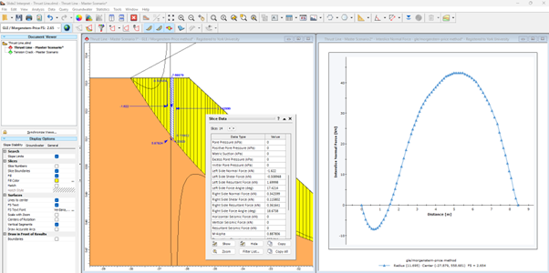
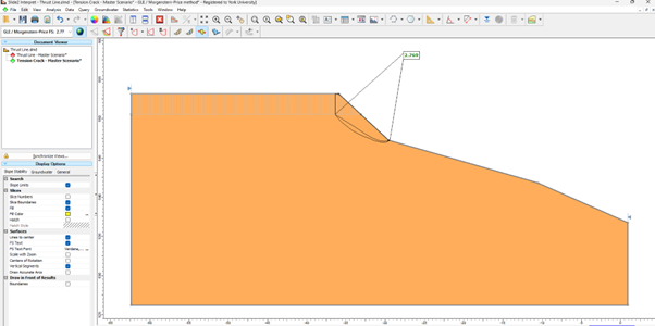
The line of thrust remains one of the most important validity checks for rigorous methods. However, it is “sadly, often ignored in practice”. This line is the locus of points where interslice forces act. Ideally, it should remain within the potential sliding mass. When it exits the boundaries or exhibits odd behaviour, the solution may be physically unacceptable even though it yields a numerical answer.
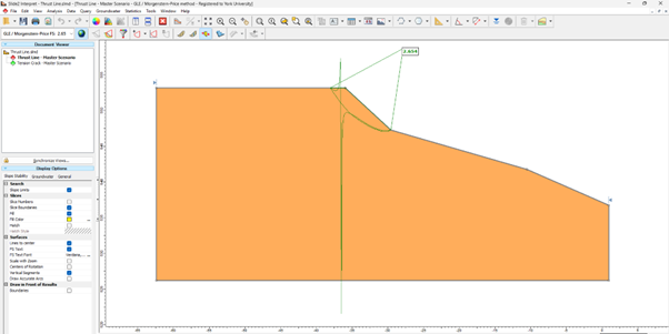
For example, in pseudo-static seismic slope stability analysis, the thrust line can exit the sliding mass when using methods that satisfy complete equilibrium. The engineer must then decide whether to accept this result, apply measures that lead the line back inside, or question whether the rigid-body assumption underlying these methods is appropriate for the problem at hand.
Tensile Interslice Forces
Rigorous methods that satisfy complete equilibrium tend to develop negative (tensile) interslice forces wherever there is a hump or kink in the potential slip surface and at the upper end of shallow surfaces (Wright, 2013; Pyke, 2017). Analysis of slopes with high-cohesion materials using rigorous limit equilibrium methods can result in tensile interslice or base forces.
USACE guidance explicitly notes that “tensile forces from cohesion” can appear at the crest in cohesive slopes, and that these are artifacts of the analysis that typically require tension cracks or other modelling adjustments.
Software documentation (e.g., Slide3) explicitly warns that where slopes exhibit high cohesion, slip surfaces through that zone may converge to solutions with tensile forces at the bases and between columns, and recommends introducing a tension crack to remove these unphysical tensile forces.
Since soil and rock masses generally have negligible tensile capacity, some experts maintain that solutions involving significant tensile forces should be rejected or modified.
The typical remedy involves inserting tension cracks. However, this raises a new question: how deep should they be? The answer often requires engineering judgment and iterative analysis; the engineer must decide whether a model with perhaps artificially deep tension cracks is realistic. (Some documentation, including Slide2’s help file, outlines theoretical considerations that help establish tension crack depth.)
Convergence
Methods that satisfy complete equilibrium can experience convergence difficulties, particularly when:
- Slip surfaces have reverse slopes near the toe.
- Pore pressures are high.
- Slip surface curvature is large.
It is important to note that non-convergence is not simply a computational inconvenience; it can yield physically unacceptable results.
Updated Guidance on the Limit Equilibrium Methods
Several limit-equilibrium methods of slices are available in commercial software. They range from simple historical procedures to rigorous complete‑equilibrium techniques. In this section, we briefly describe how these methods differ in their treatment of interslice forces and equilibrium conditions, and why some are better suited than others for specific slope geometries, loading conditions, and related factors.
Bishop Simplified Method (Bishop, 1955)
The Bishop Simplified method considers interslice normal forces but neglects shear forces. It satisfies vertical force equilibrium and moment equilibrium about the centre of rotation, but does not satisfy horizontal equilibrium.
Strengths:
- Simple formulation, widely understood and trusted.
- Fast and computationally robust convergence.
- Results are typically within 5% of rigorous methods for circular surfaces (Duncan, 1996).
- Excellent as a cross-check method.
Weaknesses:
- Does not satisfy horizontal force equilibrium.
- Experiences convergence problems when the slip surface has a reverse slope near the toe.
- Not great for translational failure modes.
Nuances of the Bishop Circular vs. Non-Circular Debate
Conventional wisdom is that the Bishop Simplified Method should be used only for circular slip surfaces. This view is theoretically valid since Bishop’s method satisfies moment equilibrium about a rotation centre by assuming normal forces on slice bases pass through this centre, which breaks down for non-circular surfaces.
Why do experts traditionally say, “circular only”?
- Mathematical foundation: Fredlund et al. (1992) demonstrated that when Bishop’s method is applied to non-circular surfaces, the factor of safety depends on the choice of moment point because the system has a net unbalanced horizontal force. This is especially problematic for slopes with earthquake loads or soil reinforcement.
- Authoritative recommendations: Abramson et al. (2002) state that they “recommend BSM to use only for the circular shear surface analysis.” Similar guidance appears in numerous textbooks and references.
Why do you see it used for non-circular surfaces anyway?
Despite the theoretical limitations described above, Bishop’s method is widely used in practice for non-circular surfaces. Modern software implementations account for the fact that normal forces do not pass through the rotation centre by calculating the moment arm associated with each normal force. According to Slide2’s documentation (2022): “Thus, most of the time, you get reasonable results for most noncircular surfaces”.
Additionally, Bishop’s computational robustness is important. The method is “virtually free from convergence problems” (Cheng & Lau, 2008), whereas rigorous approaches such as Spencer and Morgenstern-Price can struggle to converge. Research shows that, for many slope configurations, Bishop’s results are typically within 5% of those of rigorous methods.
The 2026 ‘Consensus'
Segments of the geotechnical community have evolved from a strict “Bishop = circular only” rule to a more nuanced understanding. The insights are as follows:
- For circular surfaces: Bishop is excellent; it is fast, robust, and accurate, and can be confidently used.
- For non-circular surfaces: Bishop can serve as a cross-check but should not be used as the sole method; the Spencer, Morgenstern-Price, or Janbu can be used as the primary methods. Hong Kong practice, for example, uses Bishop alongside Morgenstern-Price for non-circular surfaces and finds that “the differences between the Bishop FoS and the Morgenstern-Price FoS are, however, small” (Shiu et al., 2007); similar results have been reported by Aryal (2006). If Bishop shows significantly different results, it may indicate convergence problems in the rigorous methods rather than Bishop being “wrong”.
- When to absolutely avoid Bishop for non-circular analysis: Bishop must not be applied for slopes with significant horizontal loads (seismic, tiebacks, anchors), translational sliding modes, highly irregular geometries, or when the exit angle is steeply upward.
Janbu Simplified and Corrected Methods (Janbu, 1954; Janbu et. al., 1956)
The Janbu Simplified and Corrected methods have the following strengths and weaknesses:
Strengths:
- Handle both circular and non-circular surfaces effectively.
- Fast computation.
- The correction factor (f₀) improves accuracy by 5-12%.
- More flexible than Bishop for complicated geometries.
Limitations:
- Do not satisfy moment equilibrium.
- Experience convergence problems with high-curvature or high-pore-pressure slopes.
- Typically underestimate the factor of safety compared to rigorous methods for circular surfaces.
- The correction factor depends on the depth/length ratio and requires judgment when applying.
Recent insights:
Studies (Fredlund & Krahn, 1977; Duncan, 1996; Aryal, 2006) show that the Janbu Corrected method yields results close to those of rigorous methods for non-circular surfaces. However, the approach may be too simplistic for complicated lithologies.
Spencer Method (Spencer, 1967)
The Spencer method is best for general use, seismic analysis, and reinforced slopes. Its strengths and limitations are as follows:
Strengths:
- Simplest rigorous (complete equilibrium) method.
- Assumes constant angle of interslice forces (parallel forces).
- Handles horizontal/inclined loads well (tiebacks, anchors).
- Applicable to virtually all slopes.
- Generally reliable convergence.
Limitations:
- Convergence problems during critical surface search.
- May require tension-crack assumptions to achieve an acceptable line of thrust.
Recent insights:
The Spencer method is recommended for most applications. Studies comparing it with the Morgenstern-Price method show differences of typically less than 2% when both converge. Spencer’s constant interslice force angle assumption, while simpler than Morgenstern-Price’s variable function, rarely causes significant errors for practical problems.
The recommendation is to use Spencer for final design, seismic/dynamic loads, and reinforced slopes when accurate internal force distribution matters. Users may need to verify the line of thrust.
GLE / Morgenstern-Price Method (Morgenstern & Price, 1965; Fredlund & Krahn, 1977)
The GLE / Morgenstern-Price method is best for complex problems and when control over the interslice force function is desired. It has the following pros and cons:
Strengths:
- Users can specify the interslice force function (half-sine, trapezoidal, etc.) (although practitioners rarely do this).
- Well-established and widely implemented.
Limitations:
- Different interslice force functions can influence results.
- May require tension-crack assumptions to achieve an acceptable line of thrust.
- More complex than Spencer.
- Users must verify that reasonable lines of thrust are achieved.
Recent insights:
Research by Fredlund and Krahn (1977), Duncan (1996) and others has confirmed that factors of safety are generally insensitive to the choice of interslice force function in practical problems, with differences typically less than 5%. This addresses a long-standing concern about the method. However, for external loads (anchors, point loads), the moment equilibrium factor of safety becomes more sensitive.
Sarma Method (Sarma, 1973)
The Sarma method is best suited to slopes with discontinuities (including rock slopes) and seismic analysis. It has the following strengths and weaknesses:
Strengths:
- Handles non-vertical slice boundaries (the 1979 extension).
- Slice properties can be set independently, which allows modelling of discontinuities and faults.
- Originally developed for seismic analysis (critical acceleration approach).
- Satisfies complete equilibrium.
- Is fundamentally different from the other methods by relating interslice forces through a shear strength equation applied along the interslice boundaries themselves, not just to the base (slip surface). This means the method treats each interslice boundary as a potential failure surface where shear strength is being mobilized.
Limitations:
- More complex than the other methods.
- Requires all normal forces on block bases and sides to be positive.
- Less widely implemented in commercial software.
- Steeper learning curve.
Recent insights:
Comparative studies (Sun et al., 2011) using discontinuous deformation analysis (DDA) show that the Sarma method performs well for jointed rock slopes (when geological structures, such as faults, bedding planes, and joints, control failure mechanisms). However, it should be noted that the method assumes simultaneous failure of all internal discontinuities and the basal surface at the same safety factor. In reality, progressive failure may mean that some joints are fully mobilized while others are not.
Modern Search Algorithms and Their Impact on LEM Accuracy
Regardless of which limit equilibrium method is selected, Spencer, GLE, Morgenstern-Price, or any other, the accuracy of a slope stability analysis hinges crucially on whether the search has actually located the most critical slip surface. An analysis, for example, using a rigorous method, can still produce misleading results if the search is inadequate. Deficiencies in the slip-surface search are not inherent limitations of LEM analysis.
From Grid Search to Global Optimization
Early LEM implementations relied on grid-and-radius searches for circular surfaces and user-defined trial surfaces for non-circular problems, which were effective for simple homogeneous slopes. However, they can fail to identify critical failure modes in complex geometries (such as those with weak layers, anisotropic materials, or irregular stratigraphy). Modern software has progressively introduced global optimization algorithms. These algorithms, including Simulated Annealing, Cuckoo Search, and Particle Swarm Optimization (PSO), explore the search space far more efficiently and with minimal user input.
Surface Altering Optimization
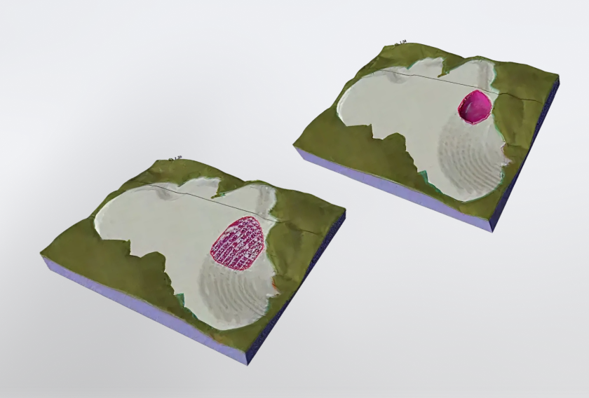
An important innovation in LEM search for critical failure surfaces is Surface Altering Optimization (SAO). It is a derivative-free local optimization method that improves the geometry of slip surfaces found by global search algorithms. SAO converts an initial surface (e.g., circular or elliptical) into a spline approximation defined by a grid of control points. It then systematically adjusts those control points to minimize the factor of safety. When combined with a global search method, SAO consistently yields lower factors of safety than the global search method alone, particularly for models with thin, weak layers and anisotropic conditions.
Additional Search Innovations
Several other algorithms have been recently developed to improve limit equilibrium analysis. These include improved algorithms for handling weak layers, multi-modal optimization and approaches for managing both convex and concave slip surfaces in non-circular analysis.
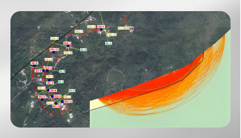
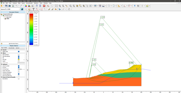
Traditional searches only find a single global minimum. This approach may miss other important failure modes. For example, open pit slopes, comprising multiple benches and material zones, can exhibit several distinct failure modes. Multi-Modal Optimization (MMO) can identify multiple critical failure surfaces simultaneously.
The search for non-circular failure modes encounters both convex and concave slip surface geometries. Concave surfaces naturally form at slope toes, while convex segments can develop where slip surfaces follow the upper boundary of an inclined weak layer; circular methods cannot capture this situation. Modern implementations allow users to control the permissible convex angles during surface generation, ensuring that physically meaningful surfaces are explored while kinematically inadmissible mechanisms are eliminated.
Lastly, some new search algorithms cross-check rigorous results against simplified methods. For example, they run Bishop or Janbu Simplified analysis alongside Spencer or GLE, which provides a rapid diagnostic. If Bishop or Janbu results show a significantly different factor of safety from the rigorous methods, it may indicate convergence problems in Spencer or GLE rather than a true difference in stability.
The FEM with Shear Strength Reduction (Griffiths & Lane, 1999; Hammah, 2005)
Over the past 20 years or more, the finite element method (FEM) has become a reliable technique for determining the safety factor of slopes. This section briefly describes the method and its role in contemporary slope stability analysis.
A Method That Has “Passed the Healthy Skepticism Test”
The finite element method with shear strength reduction (FEM-SSR) has remarkably transformed slope stability analysis. What was formerly viewed as a research tool calling for specialized expertise is now recognized as a “robust alternative to limit equilibrium slope stability analysis” that has “passed the healthy skepticism test with flying colours” (Rocscience, 2022).
How FEM-SSR Works
The concept is simple: systematically reduce the shear strength envelope of all materials by a strength reduction factor (SRF), and compute FEM models until failure occurs. Failure is typically defined by non-convergence, i.e., when no stress distribution can satisfy global equilibrium given the failure criteria (material strengths).
This technique offers a fundamental advantage: it does not require a priori assumptions about the shape or location of failure surfaces. The failure mechanism arises natively in the model zones where shear strength is insufficient to withstand the applied stresses.
When FEM-SSR can be better than Limit Equilibrium
The consensus in the last few years is that FEM-SSR is mandatory for:
- Progressive failure analysis: When parts of the slope may fail sequentially.
- Strain softening materials: Post-peak strength reduction affects stability.
- Consolidation effects: Time-dependent pore pressure changes matter.
- Complex coupled processes: Hydro-mechanical interaction, seepage with deformation.
- No obvious failure mechanism: Unknown slip surface location, shape, or failure mechanism (e.g., flexural or direct toppling).
- Reinforcement stress analysis: Need to calculate bending moments and axial forces in structural elements.
- Deformation-sensitive structures: Adjacent buildings, utilities where displacement matters.
We must add that, due to recent innovations to limit equilibrium analysis, the differences between its outcomes and those of FEM-SSR analysis for rotational, translational mechanisms, or their combination, have narrowed significantly.
Limitations
FEM-SSR is not always better, though. It has the following drawbacks:
- Requires more input parameters: Stiffness, stress-strain relationships, and dilatancy.
- Computationally more intensive: Longer run times, larger models.
- Steeper learning curve: Requires expertise in constitutive modelling and meshing.
- Calibration challenges: Deformation properties are harder to determine than strength.
- Multiple equilibrium paths: Results can depend on loading sequence and mesh refinement.
Practical Recommendations
Current best practice calls for using both LEM methods and FEM-SSR to complement each other.
- LEM for preliminary screening: Fast, code-compliant, established practice.
- FEM for complex cases: Progressive failure, coupled processes, deformation-critical situations.
- Cross-validation: When both methods give similar results, confidence increases.
- Investigation when divergent: Significant differences (>15%) warrant examining assumptions.
The 3D Question
For 3D analysis, the choice of limit equilibrium method is actually simpler than 2D; only four methods are reliably available: Bishop, Janbu, Spencer, and GLE-Morgenstern-Price.
Final Thoughts
The 2026 landscape for slope stability analysis offers more tools than ever, but it also demands greater judgment. Here are the key takeaways from the research and discussions in this article:
On Limit Equilibrium Methods
- No universal method exists. Method selection depends on failure surface shape, geology, loading, and project criticality.
- “Rigorous” ≠ “more accurate”. Methods satisfying complete equilibrium make different assumptions than simplified methods and may not be automatically more correct.
- Bishop continues to be relevant (particularly for circular surfaces), even 70 years after its introduction. It can be used for non-circular surfaces as a cross-check in 2026. The strict “circular only” rule has softened with modern software corrections and a better understanding of when it matters.
- Janbu is efficient and robust for non-circular failure surfaces and layered slopes and is great as a preliminary or companion method: it handles complex geometries and often converges where rigorous methods experience difficulties.
- Spencer and GLE/Morgenstern-Price are preferred for more rigorous analyses, but examine for convergence problems, tension and the line of thrust.
- Sarma deserves more use for rock slopes, i.e., when discontinuities control failure.
- Always check the validity of your results: line of thrust and tension (for the rigorous methods), and convergence. Software does not automatically ensure physical acceptability.
On Finite Element Methods
- FEM-SSR has matured into a production tool. It is no longer only for research or exceptional cases.
- Use FEM-SSR when deformation matters, progressive failure is possible, pore pressures are complex, or you need to model coupled processes.
- FEM does not replace LEM in routine work. A simple failure still gets a good answer from Bishop in seconds.
- The ‘best’ analyses use both LEM and FEM for critical projects; the combination utilizes the speed of LEM and the sophistication of FEM.
The question “Which method should I use?” still depends on context, but we now have a better framework for answering it. The art of slope stability analysis is not in finding “the answer” but rather in understanding which assumptions are appropriate for your problem, which methods embody those assumptions, and how sensitive your results are to uncertainty.
Regardless of which method you choose, always verify the physical reasonableness of results. As Whitman and Bailey warned in 1967 (and remains true in 2026): “The use of sophisticated methods together with a computer does not free the engineer from making a judgment concerning the reasonableness of a solution”. Engineering judgment cannot be automated, and software is a tool and not a substitute for insight.
Choose your methods wisely and check your results carefully!
References
Aryal, K.P. (2006). Slope Stability Evaluations by Limit Equilibrium and Finite Element Methods. Doctoral Thesis at NTNU 2006:66.
Bishop, A.W. (1955). "The use of the slip circle in the stability analysis of slopes." Géotechnique, 5(1), 7–17.
Cheng, Y.M. & Lau, C.K. (2008). Slope Stability Analysis and Stabilization: New Methods and Insight. CRC Press.
Ching, R. K. H., & Fredlund, D. G. (1983). Some difficulties associated with the limit equilibrium method of slices. Canadian Geotechnical Journal, 20(4), 661–672.
Duncan, J.M. (1996). State of the Art: Limit Equilibrium and Finite-Element Analysis of Slopes. ASCE Journal.
Fredlund, D.G. & Krahn, J. (1977). "Comparison of slope stability methods of analysis." Canadian Geotechnical Journal, 14(3), 429–439.
Fredlund, D.G., Krahn, J., & Pufahl, D.E. (1992). "The relationship between limit equilibrium slope stability methods." Retaining Structures, Thomas Telford, London, pp. 107–117.
Griffiths, D.V., Lane, P.A. (1999). Slope stability analysis by finite elements. Geotechnique 49, No. 3, pp. 387-403.
Hammah, R.E. (2005). The Shear Strength Reduction Method for the Generalized Hoek-Brown Criterion. Rocscience.
Hammah, R. (2021). Which Slope Stability Method should I use? Review of Most Popular Slope Stability Analysis Methods. Rocscience.
Janbu, N. (1954). Stability analysis of slopes with dimensionless parameters.
Harvard Soil Mechanics Series No. 46, Harvard University, Cambridge, MA.
Janbu, N., Bjerrum, L. & Kjaernsli, B. (1956). Slope stability calculations by the Swedish method of slices. In: Proceedings of the 2nd Conference on Soil Mechanics and Foundation Engineering, Stockholm, Vol. 3, pp. 1–17.
Morgenstern, N.R. & Price, V.E. (1965). "The analysis of the stability of general slip surfaces." Géotechnique, 15(1), 79–93.
Pyke, R. (2017). Pros and Cons of the Analysis of Slope Stability by Various Methods of Slices or Columns. pp 1-41.
Rocscience. (2022). Shear Strength Reduction Analysis – the Gift that Keeps Giving. GeoEngineer.org.
Rocscience (2025) https://www.rocscience.com/hel...
Sarma, S.K. (1973). Stability analysis of embankments and slopes. Geotechnique 23, No. 3, pp.423-433.
Sarma, S.K. (1979). "Stability Analysis of Embankments and Slopes." Journal of the Geotechnical Engineering Division, ASCE, Vol. 105, No. GT12, pp. 1511–1524.
Shiu, Y.K., Chang, G.W.K. & Cheung, W.M. (2007). Review of Limit Equilibrium Methods for Soil Nail Design. GEO Report No. 208. Geotechnical Engineering Office, Civil Engineering and Development Department, The Government of the Hong Kong Special Administrative Region, 107 p.
Spencer, G.E. (1967). "A method of analysis of the stability of embankments assuming parallel inter-slice forces." Géotechnique, 17(1), 11–26.
Sun, J., Ning, Y., Zhao, Z. (2011). Comparative study of Sarma's method and the discontinuous deformation analysis for rock slope stability analysis, Vol. 6, No. 4, pp. 293–302.
Whitman, R.V. & Bailey, W.A. (1967). "Use of computers for slope stability analysis." Journal of the Soil Mechanics and Foundations Division, ASCE, 93(SM4), 475–498.
Wright, S. G. (2013). H. Bolton Seed Lecture: Slope Stability Computations. Presented at Geo-Congress 2013, San Diego, California, USA, Geo-Institute of ASCE.