Anatomy of a Reactivated Landslide: How Combined Analysis Informed a Difficult Decision
A 21,000 m² landslide was actively threatening the settlement of Köprülü in northeastern Turkey. Ground deformation accelerated, structures cracked, and engineers needed clarity fast. This case study shows how limit equilibrium and finite element analyses — using Slide2 and RS2 — were applied to determine not just whether the slope would fail, but the failure mechanism driving it, through the integration of field observations, laboratory testing, monitoring data, and numerical modelling.
October 2015: When Stability Assumptions Failed
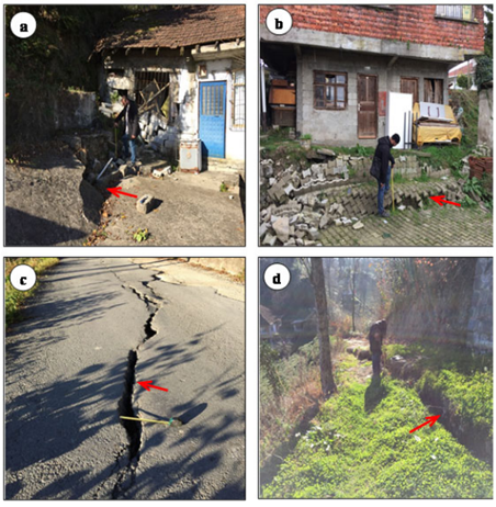
On the morning of October 15, 2015, residents of Köprülü village in Turkey’s eastern Black Sea region woke to visible ground deformation. After prolonged heavy rainfall, tension cracks cut across roads and tea gardens. Buildings tilted. Foundations shifted. Thirty-one structures sat within an active landslide zone showing no sign of arrest.
What made this case especially challenging was not just scale, but geometry. Failure was developing within slope debris overlying agglomeratic bedrock, producing a composite mechanism that could not be reliably resolved through a single analytical method.
Geological Context: A Reactivated Paleo‑Landslide
Köprülü village is located in Turkey’s eastern Black Sea region on slopes inclined between 20° and 30°, formed not by recent geomorphic processes but by an ancient paleo-landslide that had long appeared dormant. The arc-shaped landslide crown, approximately 900 m in length, coincides with a northeast-trending vertical fault that acts as the primary structural control on slope behaviour.
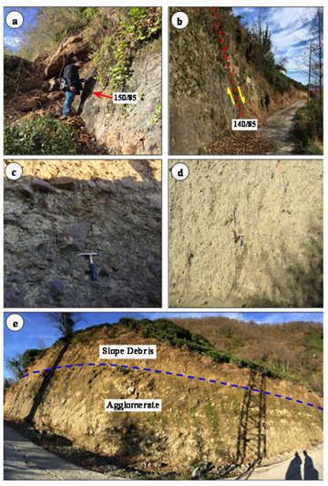
The geological profile consists of heterogeneous slope debris overlying basaltic agglomerates of the Eocene-aged Kabaköy Formation. Slope debris thickness varies from 6 m to 25 m and comprises angular blocks, pebbles, sands, silts, and clays derived from the fault's footwall. The underlying agglomerates are weakly cemented, intensely weathered, and highly fractured, containing rounded to angular pyroclasts typically ranging from 2 to 40 cm.
The total affected area spans approximately 21,000 m². Groundwater governs stability: annual rainfall reaches 2,500 mm, and pervasive fracturing with low cementation promotes elevated pore pressures and localized discharge. Under these conditions, slope stability is inherently conditional — failure governed primarily by changes in groundwater regime rather than surface loading alone.
Building the Forensic Model: Investigation Before Analysis
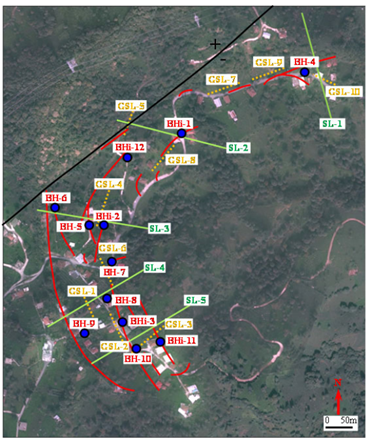
Because the landslide was active and directly threatened occupied structures, the investigation strategy focused on minimizing subsurface uncertainty before numerical analysis. The study area was divided into four slope sectors, within which five survey lines were defined to capture variations in geometry, stratigraphy, and groundwater conditions.
Twelve boreholes were drilled to 25 m depth, totaling 300 m of cumulative drilling. Borehole logs confirmed 6 to 25 m of slope debris overlying basaltic agglomerates. Groundwater depths ranged from 9 to 20.5 m below ground surface across most locations, with a notable exception along Survey Line 5 where groundwater approached the surface, indicating localized discharge.
Ten seismic refraction profiles characterized the dynamic elastic properties of both materials, providing deformation moduli and Poisson's ratios required for finite element analysis. Five boreholes were equipped with inclinometers to track depth, direction, and speed of movement. Displacement rates ranged from 0.05 to 1.8 mm/day — classified as extremely slow to very slow. Monitoring confirmed that failure initiated within slope debris and propagated into underlying agglomerates.
Using integrated data from boreholes, geophysical surveys, and inclinometer monitoring, five geological cross-sections were constructed. These cross-sections served as the geometric basis for all subsequent Slide2 and RS2 analyses.
Material Properties and Parameter Derivation
The investigation team established material properties for both slope debris and agglomerates through laboratory testing, geophysical investigation, and back-analysis. Laboratory testing followed ISRM-suggested methods and included consolidated-undrained (CU) triaxial tests on saturated samples, point load tests, and uniaxial compressive strength (UCS) tests.
Laboratory testing yielded the following peak material properties:
- Peak cohesion
- Internal friction angle
- Natural unit weight
- Point load index
- Uniaxial compressive strength
- Elastic modulus
To support finite element modelling, seismic refraction surveys were used to estimate deformation moduli and Poisson’s ratios for both material units.
Because the landslide was already active, peak strength parameters were not representative of conditions along the failure surface. Instead, residual shear strength parameters were calculated by limit equilibrium back-analysis, assuming the slopes were at limiting equilibrium at the time of failure.
The back-calculated residual parameters adopted in both Slide2 and RS2 analyses were:
- Slope debris:
- Cohesion = 11 kPa
- Internal friction angle = 11.5°
- Agglomerates:
- Cohesion = 150 kPa
- Internal friction angle = 14.8°
These residual values formed the governing strength parameters for all forward analyses, ensuring consistency between modelling approaches and alignment with observed field behaviour.
Slope Stability Analyses
The team performed slope stability analyses using Slide2 and RS2, applying residual shear strength parameters from back-analysis. Both tools were used deliberately and in parallel, allowing direct comparison between limit equilibrium and finite element results across all five survey lines.
For consistency, the following modelling assumptions were applied in both analyses:
- Mohr-Coulomb failure criterion for slope debris and agglomerates.
- Residual cohesion and friction angle values derived from back-analysis.
- Tension cracks, as observed in the field.
- Static surcharge loads to represent existing buildings.
- Fully saturated conditions, modelled using the auto water table (Hu) to account for rainfall-induced pore pressures.
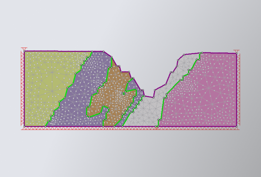
In Slide2, the Janbu method was selected to accommodate the elongated geometry of the slopes and the composite nature of the failure surfaces. RS2 finite element models were constructed using six-noded triangular elements with refined zoning near lithological boundaries, allowing stress redistribution and deformation patterns to be captured under gravitational loading.
Across all five survey lines, the factor of safety was consistently below 1.0, ranging from 0.366 to 0.642 in Slide2 and 0.35 to 0.64 in RS2. Overall agreement between the two methods was strong, with RS2 generally producing slightly more conservative results.
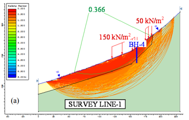
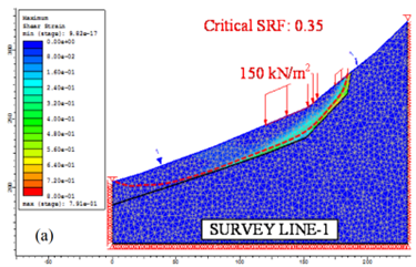
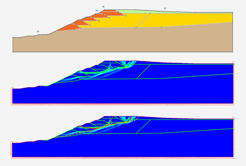
Results from Survey Line 1 illustrate this convergence clearly, shown in figure 4. Both Slide2 and RS2 identified a talus-type slide with composite geometry, initiating in the slope debris, following the debris–agglomerate contact, and extending into the underlying agglomerates. While Slide2 revealed multiple potential slip surfaces reflecting progressive failure, RS2 highlighted the dominant failure mechanism through localized zones of high deformation.
Engineering Reality Check: Why Stabilization Was Abandoned
A pile-supported stabilization system was evaluated using both Slide2 and RS2: double rows of 1-meter-diameter bored piles, 30 meters deep. Both analyses confirmed the design would achieve long-term stability with adequate factors of safety. Numerically, the solution worked. Practically, it failed.
The 900-meter landslide crown would require approximately 800 piles — each drilled through actively deforming ground moving up to 1.8 mm/day, in terrain occupied by houses and economically vital tea gardens. Construction would span years while the landslide continued to progress. The cost would be extraordinary, construction risks substantial, and the social impact severe, as families would lose both homes and livelihoods during installation.
The analyses led to a difficult but defensible conclusion: relocation offered a safer and more reliable means of risk reduction than attempting to restrain a large, reactivated paleo-landslide through structural intervention.
What This Case Teaches Us
This study demonstrates how Slide2 and RS2 function together as a decision-making framework, not just calculation engines:
- Field data defines the problem – Inclinometers revealed ongoing movement and validated the composite failure mechanism.
- Monitoring validates assumptions – Ground truth from five boreholes confirmed that residual parameters and slip depths matched predictions.
- Limit equilibrium identifies failure likelihood and geometry – Slide2's multiple slip surface search captured the progressive nature of the failure.
- Finite element analysis reveals stress-driven mechanisms – RS2's strength reduction showed where instability would propagate.
When these lines of evidence converged, the outcome was not just a factor of safety — but confidence in judgment. And sometimes, that judgment means recognizing when construction isn't the answer.
Closing Thoughts
The Köprülü Village landslide reminds us that slopes are systems with memory. They record ancient failures, respond to modern triggers, and resist simple fixes. By integrating monitoring data with Slide2 and RS2 analyses, engineers were able to move beyond guesswork and arrive at a defensible, evidence-based decision.
Understanding when not to build is just as critical as knowing how.
Integrate field monitoring with advanced slope analysis
Explore how Slide2 and RS2 work together to validate your engineering judgment.
Start your free trial today