Tunnel Lining Design for Modern Metro Infrastructure With RS3
Building a wide tunnel beneath a major city is always a challenge, but excavating fractured rock above a pre-existing Montréal tunnel was a true engineering feat. This case study shows how RS3 helped validate a composite shotcrete design that kept one of Montréal’s shallowest junctions stable at every stage of construction. For the full story, read the full research paper from Shahriyar Heidarzadeh, Nooshin Falaknaz, and Alun Thomas.
The Geological Setting
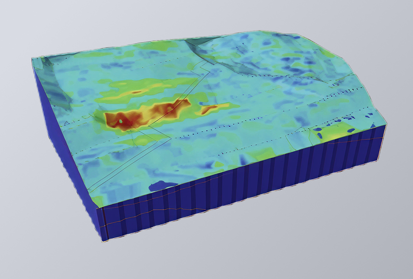
As part of the Blue Line subways extension in Montréal, engineers were tasked with designing the city’s widest underground metro junction, featuring spans up to 19.8 metres, beneath a dense urban environment. This shallow construction, combined with low in-situ stress conditions, can cause the rock failure on top of the tunnel. To maintain the maximum allowable settlement on the ground surface, the design of the lining system is very crucial.
The overburden consisted of approximately 5 metres of fill and till, 3 metres of fractured limestone, and 5 metres of interbedded sound limestone and shale from the Tétreauville Formation. The Hoek–Brown constitutive model was used to describe the behavior of rock mass, were the stiffness and strength parameters were derived using laboratory testing and empirical methods. The fractured rock exhibited a GSI of 25, while the sound rock reached 57. These parameters were used to create a 3D numerical model in RS3, designed to simulate both the geotechnical behaviour and structural interaction between the rock and tunnel support system.
The Challenge
Designing a wide-span tunnel under shallow cover presents significant structural and geotechnical challenges. In conventional tunnelling, primary and secondary shotcrete linings function independently: the primary offers early support, while the secondary adds durability and finishes. But at only 13 metres depth — with potential for up to 8 metres of future excavation above — the primary liner risked being overstressed over the loading/unloading conditions.
This risk included the cracking and delamination of the lining layers due to the formation of tensile and shear forces in the tunnel crown. The support system needed to withstand these shifting loads, maintain integrity throughout staged excavation, and remain durable under long-term variable conditions.
The Solution
To overcome these constraints, the team designed a Composite Shotcrete Lining (CSL) system which included:
- A permanent primary shotcrete layer (BP1)
- A spray-applied waterproofing membrane
- A bonded secondary shotcrete layer (BP2)
Together, these layers formed a unified structural shell. The interface between two shotcrete layers was modelled using Mohr-Coulomb slip criteria with the waterproof condition, with a peak cohesion of 750 kPa, a friction angle of 26°, and a tensile strength of 350 kPa.
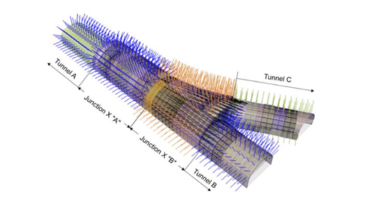
The 3D model in RS3 was developed to simulate the construction sequence, which included the excavation of top heading and benching, installation of permanent rock bolts, and lining system for BP1 and BP2 with the time-dependent strength gain of shotcrete. Loading scenarios included in-situ stresses, simulated traffic loads (17.6 kN/m²), excavation of an 8-metre surface layer, and a 250 kPa surface surcharge to represent a legal easement for future development.
The Results
At the end of junction excavation (stage 35), the major principal stress (σ₁) in the crown remained compressive — between 1 and 1.5 MPa, peaking at 2 MPa near the rock pillar. Total displacements stayed below 1.2 mm, and no tensile stresses (σ₃ < 0) were observed in the surrounding rock. Even after excavation of the additional 8 metres of overburden (Stage 36) the tunnel remained in compression throughout.
Axial forces in rock bolts stayed well within design limits across all zones. BP1 saw a transition from ~150 kN of compressive force at Stage 35 to –130 kN of tension during unloading in Stage 36, returning to compression when the 250 kPa surface load was applied in Stage 37. BP2 mirrored this response, reaching –120 kN of tension along the walls. Both liners remained safely within design limits set by their respective N–M and N–Q diagrams (support capacity envelope).
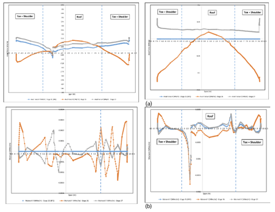
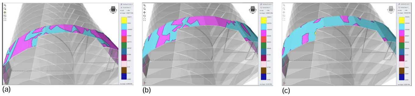
The membrane interface functioned as designed. At Stage 35, normal stress across the membrane was largely compressive. During overburden excavation, these values reversed to a peak of 36 kPa in tension, then returned to compression (up to 34 kPa) once the surface surcharge was applied — always within the membrane’s bond strength.
The Verdict
The composite shotcrete lining allowed engineers to safely construct Montréal’s widest underground junction beneath exceptionally shallow cover. RS3 provided the modelling environment needed to evaluate the full excavation sequence, understand liner interactions, and assess stress redistribution through every stage of loading.
The CSL approach proved to be structurally sound and efficient, plus adaptable to future development. With both shotcrete layers acting as a unified system, even under reversed loading, the design delivered reliable, resilient performance in one of the city’s most demanding tunnelling conditions.
Build Smarter Tunnels With RS3
Model excavation stages, evaluate support systems, and simulate complex tunnel interactions with precision. Start your free trial of RS3 today.
Learn More About Tunnel Design
Use the resources below to strengthen your understanding of tunnel modelling, support design, and excavation sequencing in RS3.
What are the Different Types of Tunnelling and Excavation Methods?
Tunnelling methods vary based on geology, depth, and project requirements, but most fall into a few key categories. Drill-and-blast tunnelling is commonly used in hard rock conditions and involves sequential excavation and support installation. Tunnel Boring Machines (TBMs) are preferred for long, continuous tunnels, especially in urban or soft ground settings, due to their precision and reduced surface disruption. Sequential Excavation Method (SEM) or New Austrian Tunnelling Method (NATM) is widely used in variable ground, allowing for staged excavation and flexible support design. Other methods include cut-and-cover (for shallow tunnels) and immersed tunnelling (used underwater).
What Support Systems Are Used in Tunnel Design?
Tunnel support systems stabilize excavation, control deformation, and ensure long-term safety. Common support types include rock bolts for reinforcing the surrounding rock mass, shotcrete (sprayed concrete) for surface support and load transfer, and steel sets or ribs for structural reinforcement in weaker ground.
Other systems may include wire mesh, lattice girders, and precast concrete segments, depending on the tunnelling method and ground conditions. In numerical tools like RS3, these supports can be simulated to evaluate their interaction with the rock and optimize their placement and capacity.
Resources to Build Your Tunnel Design Skills in RS3
More Helpful Rocscience Software for Tunnelling
- RocTunnel3: A powerful tool for cross-sectional analysis and rapid tunnel support design, ideal for early-stage evaluations and circular tunnel profiles.
- RS2: 2D finite element analysis for staged excavation and support design, suited for SEM, NATM, and shallow tunnel modelling.
- Slide3: 3D limit equilibrium analysis for assessing portal stability, cut-and-cover sections, and complex slopes near tunnelling zones.
Feature Highlight: RS3’s Tunnel Designer
Start your free trial of RS3 and see how your tunnel designs hold up under real-world conditions.
Free Trial