Stress Meets Structure: Modelling Spalling in Jointed Rock with RS2 and CVBM
The Hidden Threat 420 Meters Below
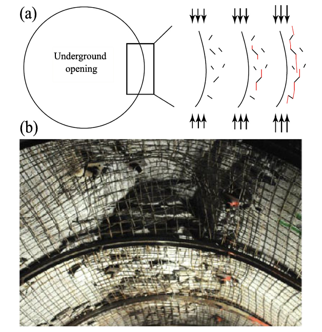
Deep underground excavations operate within a narrow margin between equilibrium and failure. As confinement decreases at an excavation boundary, stresses redistribute and concentrate around the opening. In strong, brittle rock, this process can lead to tensile cracking parallel to the excavation wall, progressive slab detachment, and the development of V-shaped notches — a phenomenon known as spalling.
When not anticipated, spalling may contribute to overbreak, increased support demand, schedule disruption, and elevated safety risk. Predicting this behaviour remains challenging because many classical studies assume intact rock conditions. In practice, natural discontinuities are almost always present, and their interaction with stress-induced brittle damage is complex and nonlinear. Depending on their geometry and mechanical behaviour, discontinuities may intensify damage, reduce it, or alter its geometry and extent.
This article summarizes key findings from a recent peer-reviewed study published in Computers and Geotechnics (2024) and discusses their practical implications through numerical modelling using Rocscience’s RS2 and the Continuum Voronoi Block Model (CVBM). The focus is on how structural geology interacts with high in situ stress to influence brittle failure mechanisms and excavation performance.
Understanding Spalling as a Stress-Driven Process
Spalling initiates when excavation removes radial confinement while tangential compressive stresses increase around the opening. Within this compressed zone, local heterogeneities may generate tensile stresses that initiate fractures parallel to the excavation surface. As fractures propagate and coalesce, slabs detach inward until confinement increases sufficiently to limit further tensile cracking.
Because the mechanism is highly confinement-sensitive, any structural feature capable of redistributing stress — particularly through shear slip — may influence the depth, geometry, or occurrence of spalling.
Modelling Brittle Failure with CVBM in RS2
Numerical approaches to brittle failure typically fall into three categories:
- Continuum models, which are computationally efficient but rely on phenomenological damage laws;
- Fully discontinuous models, which explicitly simulate fracture mechanics but can be computationally intensive at field scale;
- Hybrid or pseudo-discontinuous approaches, which aim to balance realism and practicality.
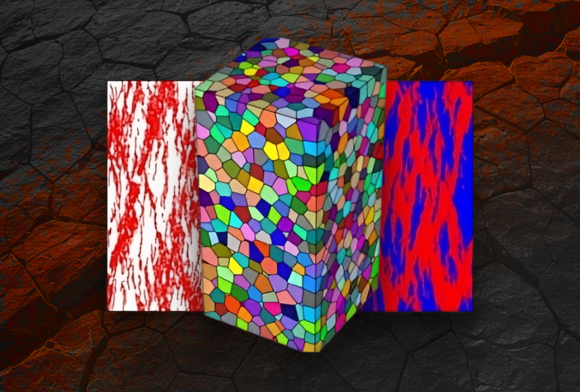
The Continuum Voronoi Block Model (CVBM), implemented in RS2, represents this hybrid approach. The rock mass is discretized into Voronoi blocks connected by joint elements, while each block is internally meshed using finite elements. This structure preserves continuum behaviour while allowing fractures to develop explicitly along block boundaries.
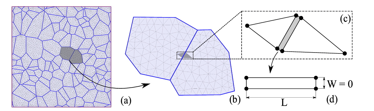
Blocks and joints follow a Mohr-Coulomb framework with tensile cutoff and post-peak strength reduction to capture brittle behaviour. Post-peak strength reduction enables simulation of brittle behaviour observed in hard rock, while maintaining physically interpretable parameters and manageable computational demands.
Validation Using the Mine-by Tunnel
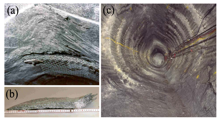
The modelling approach was benchmarked against the Mine-by tunnel at the Underground Research Laboratory in Manitoba, Canada. The circular tunnel (3.5 m diameter) was excavated mechanically at approximately 420 m depth in Lac du Bonnet granite under high differential stress conditions. Recorded in situ stresses were on the order of σ₁ ≈ 60 MPa and σ₃ ≈ 11 MPa, with the tunnel aligned close to the intermediate principal stress direction.
Field observations documented progressive spalling to approximately 0.53 m depth and a characteristic V-shaped notch. Initial simulations using laboratory strength parameters produced limited damage, highlighting the difference between laboratory-scale strength and field-scale behaviour.
Model Setup and Calibration
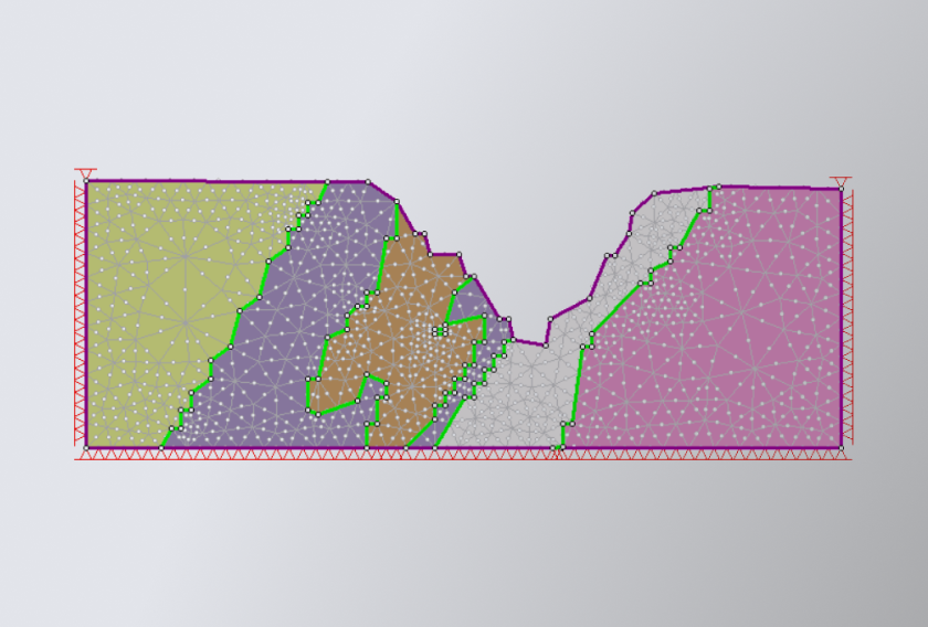
The RS2 model incorporated a CVBM region surrounding the excavation, while the far field was represented using elastic material to minimize boundary effects. The Voronoi discretization employed an average block size of approximately 75 mm, resulting in a mesh of roughly 60,000 finite elements. Excavation advance was simulated using an 11-stage stress-relaxation approach to represent progressive stress redistribution during tunnel development.
Initial simulations using laboratory-derived strength parameters produced minimal damage, highlighting the well-recognized difference between laboratory-scale strength and field-scale brittle rock behaviour.
Subsequent calibration simulations were performed to identify appropriate strength reduction factors for both Voronoi blocks and joint interfaces. Cohesion values of approximately 41.5 MPa for blocks and 22.5 MPa for joints provided the closest agreement with observed field behaviour, successfully reproducing both the depth of spalling and the characteristic V-shaped notch geometry. A comparison between calibrated numerical results and field observations is presented below.

After calibration of block and joint cohesion values, the CVBM model reproduced both the observed spalling depth and failure geometry. Damage localized in regions where confinement dropped below roughly 10% of uniaxial compressive strength, consistent with established spalling thresholds and acoustic emission observations.
With validation established, discontinuities were introduced systematically.
Parametric Analysis: Quantifying the Role of Discontinuities
With the Mine-by case successfully reproduced, the study moved to its most consequential stage: a structured parametric investigation of discontinuities using a Discrete Fracture Network (DFN).
Discontinuities were represented in RS2 using Goodman joint elements embedded within the CVBM framework. A reference DFN configuration was first established, defining baseline orientation, spacing, persistence, and mechanical properties. From this reference case, individual parameters were varied systematically. In total, 21 scenarios were evaluated by varying orientation, spacing, persistence, position relative to excavation, friction and stiffness, and two-set combinations.
The intact case served as the control condition. All DFN scenarios were assessed relative to this benchmark. Across these simulations, discontinuities influenced brittle failure primarily through stress redistribution.
1. Orientation Influences Stress Redistribution
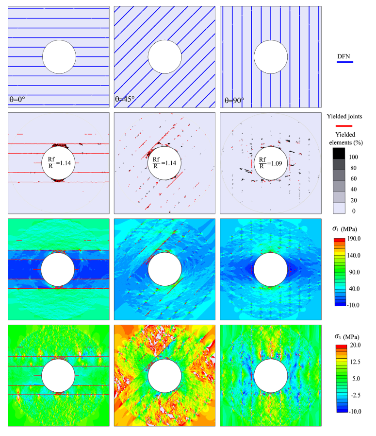
Joint orientation relative to the major principal stress (σ₁) was the dominant control.
When joints were oriented approximately perpendicular to σ₁, shear slip redistributed stress away from the excavation boundary. Vertical joints redistributed stress toward the sidewalls, increasing confinement in crown and invert zones, reducing spalling depth.
Unfavourable orientations rotated stress concentrations into critical zones and could intensify damage.
Discontinuities do not simply weaken rock. They redirect the stress field.
2. Shear Permission Influences Damage Evolution
Among the tested cases, intermediate spacing allowed joints to slip while intact rock bridges carried compressive load. This combination produced the smallest deterioration zones.
When spacing was too small, thin rock slabs could not sustain compression. When spacing was too large, behaviour resembled intact rock and stress relief vanished.
Persistence introduced a counterintuitive effect. Lower persistence (25-50%) concentrated stress at joint tips, triggering additional fracture propagation in intact bridges. In some cases, this increased damage beyond the fully persistent case.
Mechanical property variations revealed nonlinear response. Increasing friction angle or stiffness initially improved stability. Beyond a critical point, suppressed slip forced stress back into intact rock, amplifying brittle failure.
Discontinuities relieve stress only when their geometry and mechanics permit shear.
3. Structural Networks Modify Stress Distribution
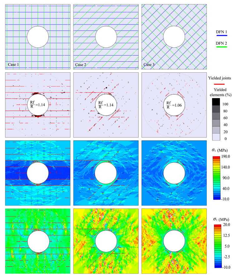
Two intersecting joint sets oriented approximately ±45° to σ₁ produced the smallest overall failure zones in several scenarios. Stress concentrations became more diffuse. Tensile sidewall failure was eliminated in certain configurations.
In other words, structural complexity does not automatically degrade stability. Under specific orientations, it redistributes confinement more evenly than intact rock alone.
The Unifying Principle
Across the evaluated scenarios, discontinuities primarily acted as stress redistributors. When shear slip occurred within low-confinement zones, spalling was often reduced. When slip was inhibited or stress concentrated at joint tips, brittle damage increased.
These findings highlight that spalling in jointed rock is governed by the interaction between stress and structural geology rather than intact strength alone.
Design Implications for High-Stress Excavations
For deep underground projects, the results emphasize several practical considerations:
- Evaluate discontinuity orientation relative to principal stress directions.
- Assess spacing and persistence in terms of rock bridge capacity.
- Consider excavation positioning relative to mapped structures.
- Recognize that higher joint strength or stiffness may suppress beneficial slip.
- Use parametric modelling to bound likely behaviour rather than assume worst-case weakening.
CVBM within RS2 provides a finite-element framework capable of capturing both stress redistribution and fracture development, supporting more informed excavation design assessments.
From Mechanism to Prediction
The Mine-by validation demonstrates that stress-driven brittle failure can be reproduced numerically when calibration accounts for field-scale behaviour. The DFN study further shows that discontinuities may significantly influence how spalling develops by reshaping the stress field around excavations.
When stress conditions and structural geology are evaluated together, brittle damage becomes more predictable, allowing engineers to better anticipate excavation performance and manage design risk.
Evaluate how discontinuities may influence stability in your next high-stress excavation
Explore RS2’s CVBM capabilities
Start Your Free Trial