Settle3's New Section Designer
Settle3 is one of the industry's leading 3D Settlement and Foundation Analysis tools. It allows you to analyze vertical consolidation and settlement under foundations and can be used for applications including embankments and foundations.
This year we worked on revamping Settle3's Section Designer and this new tool gives you more control and flexibility over your material layers. Now you can not only draw a soil profile without any limitations but even control pockets of materials in your model.
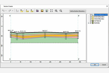
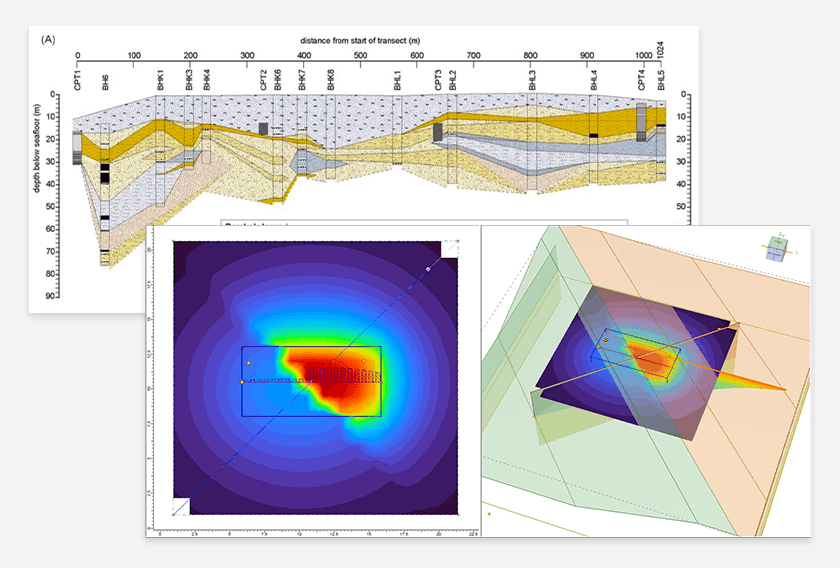
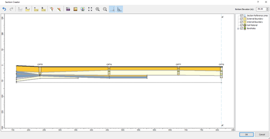
Previously, you would have to draw the section which extends from one end to the other end with a continuous line and this presented some challenges and limitations when modelling engineering cases with discontinuous soil layers, sinkholes, utility trenches, pipeline structures, etc. These challenges are now resolved in the section creator enabling you to freely draw any shape you want from your boreholes. Some examples of the more complex soil profile with multiple boreholes that have discontinuous layers are shown below.
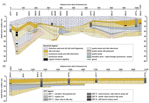
Figure A below shows a soil profile drawn with more complex soil layers, while Figure B shows simpler but at the same time, discontinuous soil profile layers at the bottom of the CPT holes.
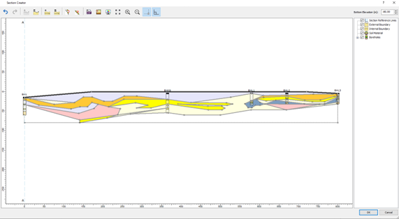
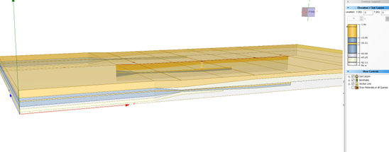
With the improved section creator, a similar profile can be modelled using the section creator in Settle3. After the soil model is created in the section creator, you can apply loads and add query point, query lines, or field grid point to see the settlement analysis results. However, note that the settlement is calculated based on the assigned soil material along the depth/elevation of the soil profile. For instance, there’s a stiff soil layer on the left side of the soil profile, followed by the softer soil region on the right side of the load. With the use of improved section creator, you can freely model this soil condition with the use of vertical boundaries in the section creator.
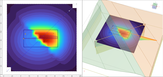
The soil materials can be assigned with different material properties to visualize the difference in settlement analysis results which corresponds to the soil material property below the load along the depth/elevation of the soil model. The model below shows the soil profile created using a vertical boundary which allows users to define two distinct soil profiles in a model. Settlement on the right side of the load is more prevalent than the settlement on the left section of the load as shown below in Figure C.
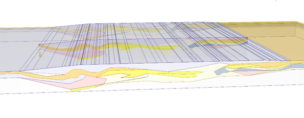
Therefore, you can now freely create any geometry as you like to define in the section creator, which you can then extrude into a 3D soil model for settlement analysis.