New CSA and Eurocode Design Standards in Slide2 and Slide3
- Sina Javankhoshdel,
- Liam Sy, Geotechnical Software Developer at Rocscience
In geotechnical engineering, the difference between an acceptable design and a resilient one rarely comes down to analytical sophistication alone. More often, it hinges on how rigorously evolving design standards are interpreted and applied. As regulatory frameworks continue to mature — driven by research, field performance, and hard-earned lessons — engineers are asked to meet higher expectations for both safety and efficiency, often across multiple jurisdictions.
Design standards are not administrative hurdles. They codify professional judgment. Each clause reflects accumulated experience about how systems behave under uncertainty and where margins truly matter. Yet these standards do not stand still. Keeping pace requires tools that implement them faithfully, without diluting their intent or constraining engineering insight.
With the upcoming releases of Slide2 v9.041 and Slide3 v3.034, Rocscience expands support for contemporary international practice through the addition of the Canadian Highway Bridge Design Code CSA S6:19 and the 2024 Eurocodes. These updates connect modern design philosophy directly to practical slope stability analysis, enabling engineers to work directly within the frameworks that govern real projects.
Understanding Design Standards and Load Combinations
At the core of any design standard is the systematic application of factors to different components of an engineering model. These factors, applied through prescribed combinations, are intended to represent credible worst-case scenarios. They introduce redundancy, reduce the probability of failure, and acknowledge the inherent uncertainty in material properties, loads, and modelling assumptions.
In practice, this means applying combinations of factors that may reduce material strengths, properties, or resistances, while increasing the severity of loads, whether permanent (dead) or variable (live). These combinations are not arbitrary, nor are they a simple stacking of every possible extreme. For example, seismic loads are often excluded from strength-based combinations or treated separately, as this would likely cause an overdesign for a very rare loading scenario.
The definition of which factors apply, and where, is set by the governing body behind each standard. Correct implementation is therefore central to both regulatory compliance and defensible engineering design.
The latest releases of Slide2 and Slide3 expand this foundation with carefully selected combinations from each standard. Building on previously available standards, Slide2 and Slide3 now include the following additional combinations:
Standard |
Combination |
Description |
CSA S6:19 |
Combination 1 |
Governing dead and live load combination |
Combination 5 |
Governing seismic combination |
|
Combination 9 |
Governing dead load focused combination |
|
AASHTO 2024 |
Strength I |
Same as 2020 combination |
Extreme I |
Same as 2020 combination |
|
Eurocode (BS EN 1990:2023 and associated BS EN 1997-1, 1997-2, and 1997-3) |
Fundamental |
Permanent and variable combination for slope design |
Seismic |
Seismic case |
Applying Design Factors: LRFD versus Partial Factors
Over time, different factoring philosophies have emerged as engineering practice has evolved. Understanding these differences matters — not as academic exercise, but because they fundamentally shape how we evaluate design adequacy.
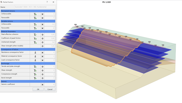
The Eurocodes adopt a Partial Factor approach, where material properties such as cohesion, friction angle, and support capacity are reduced by dividing characteristic values by factors greater than 1. This method explicitly embeds uncertainty into material strength definitions. By contrast, Load and Resistance Factor Design (LRFD), used by AASHTO and CSA, centres on the concept of a nominal resistance. This resistance is multiplied by a factor less than 1, while loads are increased using factors greater than 1. Both approaches aim to achieve consistent reliability, but they do so through different mathematical lenses.
The 2023 revision of BS EN 1990, together with its associated geotechnical standards, introduces a more unified framework for slope and embankment design compared to the 2004 Eurocodes. Partial factors are taken from material set M2 and verification case VC2, closely aligning with the legacy Eurocode implementations previously available in Slide2 and Slide3.
A significant addition is the consequence factors. These provide an added level of safety based on the severity of potential failure consequences, applied to material strengths, support properties, and loads. The approach acknowledges that not all failures carry equal weight — a slope threatening critical infrastructure demands different treatment than 1 in a remote area.
AASHTO and CSA allow engineers to apply a global resistance factor as an alternative to partial factors. In this approach, the final slope resistance is multiplied by a single factor, often on the order of 0.65, depending on the governing standard and application. CSA also incorporates consequence factors but applies them directly to resistances rather than loads or material properties.
There is no single universally superior approach. Each methodology has strengths and limitations, and performance can vary depending on the problem being analyzed. What matters is that these frameworks enable engineers to design solutions that are both robust and efficient, aligned with regional codes and the risk profiles of specific projects.
The practical impact of these standards becomes clear when comparing factored and unfactored analyses on the same geometry.
Example Application
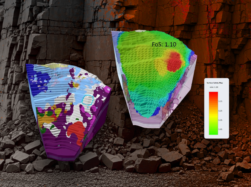
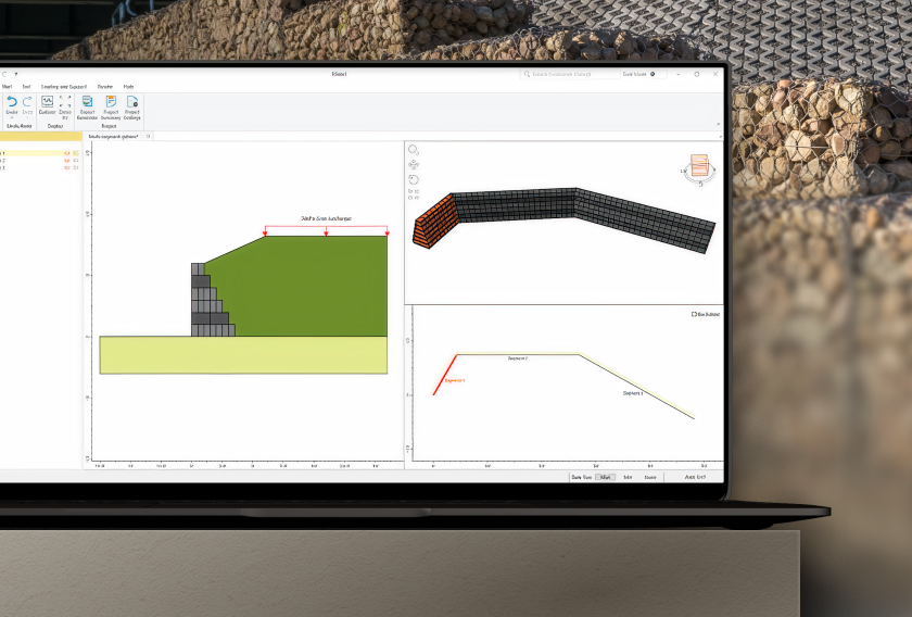
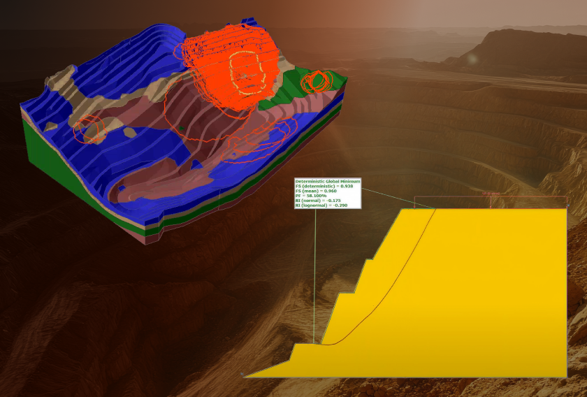
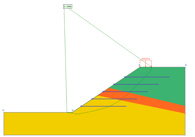
Consider a slope with a surcharge at the crest and geogrid reinforcement. When analyzed without any design standard applied, the computed factor of safety is approximately 1.5.
In many contexts, a factor of safety of 1.5 might appear acceptable. However, when the same model is evaluated using the AASHTO 2024 Strength I combination and the Eurocode Fundamental design combination, the resulting factors of safety are significantly lower than 1.5.
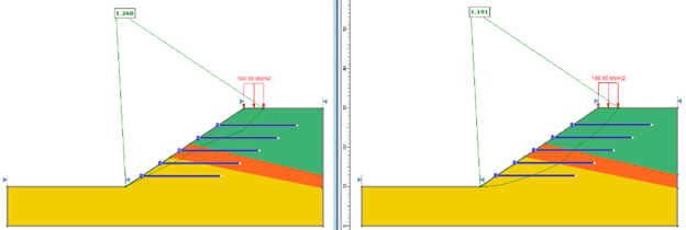
These results indicate that the design may not satisfy the requirements of either standard and could be susceptible to failure under the specified conditions. In practice, this outcome informs the need for redesign to meet the intent and safety margins of the governing codes.
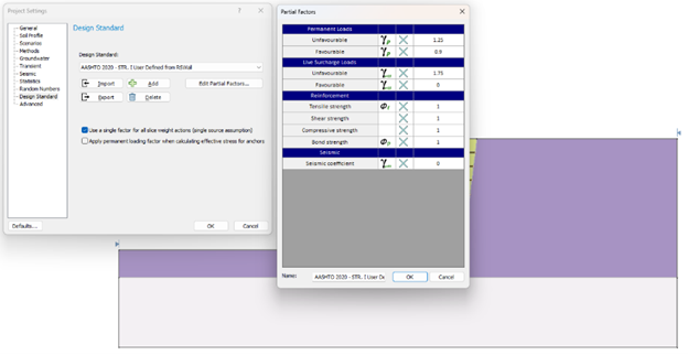
Slide2 and Slide3 also allow users to define custom design standards based on any of the pre-defined combinations. Engineers can modify individual factors as needed, an approach commonly used when exporting design standard information from RSWall.
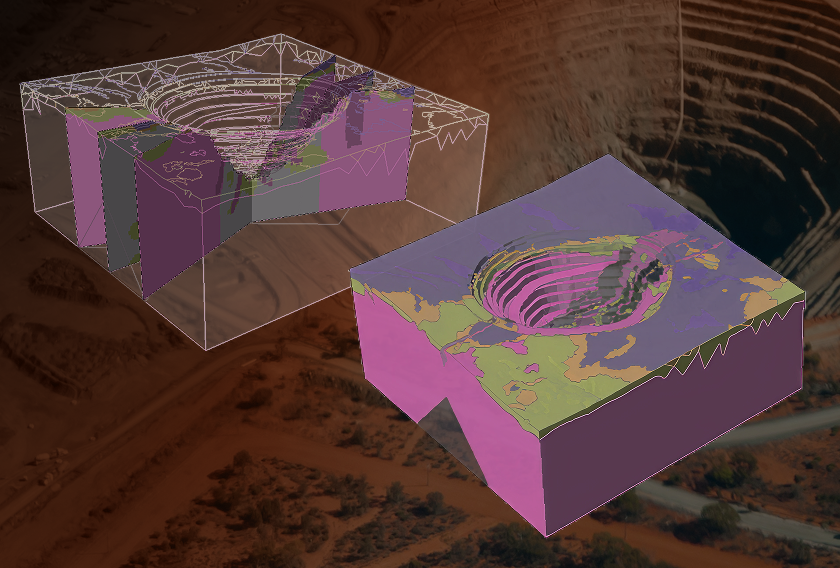
Design standards are preserved during interoperability workflows. A design standard file can be imported directly into Slide3, or a representative section can be exported into Slide2. In both cases, the associated design standard is carried through. For example, when importing a Eurocode-based case into Slide3, the computed factors of safety increase slightly, as expected for a three-dimensional analysis, yet remain below 1.5.
Integration with RSWall
RSWall models can be exported directly to Slide2 for global stability assessment. The load combinations and factors defined in RSWall are transferred as a user-defined design standard, allowing engineers to maintain consistency between wall design and overall slope stability analysis.
For example, an MSE wall designed in RSWall using AASHTO 2024 factors can be exported into Slide2.
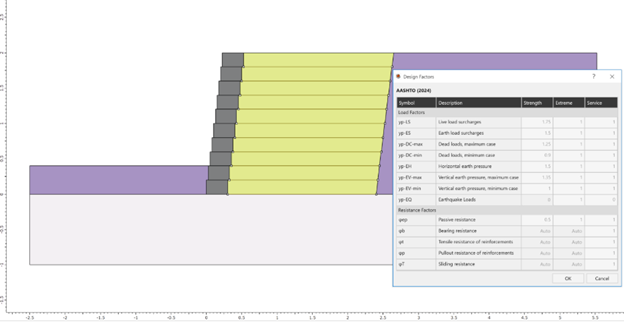
Upon import, the same factors appear as a user-defined standard, where they can be reviewed or adjusted as required for the broader stability context.
This integration supports a continuous design workflow, reducing duplication, minimizing transcription errors, and reinforcing alignment with the selected design code from concept through verification.
Closing Perspective
Design standards are not static constraints. They are living expressions of engineering knowledge, shaped by research, field performance, and evolving risk tolerance. By embedding the latest CSA, AASHTO, and Eurocode provisions directly into Slide2 and Slide3, Rocscience ensures that engineers are working with tools that reflect current practice rather than legacy assumptions.
This is not about adding options for the sake of completeness. It is about giving engineers clarity, confidence, and control when navigating complex design decisions under real-world constraints. As standards continue to evolve, so will the tools that implement them, grounded in rigorous theory and proven in practice.
Move from interpretation to application
Evaluate CSA and Eurocode design standards in Slide2 and Slide3 with your own slope models.
Start your free trial today