Going Beyond Conventional 1D Seismic Site Response Analysis: An Essential Bridge Towards Liquefaction Modelling and Robust Multi-dimensional Seismic Analysis
- Dylan Centella, Geotechnical Product Manager at Rocscience
- Dr. Youssef M A Hashash, at University of Illinois Urbana-Champaign
Introduction
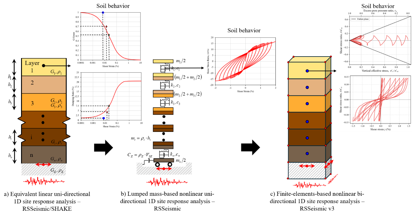
Rocscience is delighted to introduce a new Finite Element (FE)-based one-dimensional (1D) site response analysis workflow in RSSeismic. For more than five decades, 1D site response analysis has provided engineers with an efficient and practical framework for evaluating how local soil conditions modify earthquake ground motions. Over this period, several analysis approaches were developed, including linear methods, equivalent linear procedures that iteratively update soil properties based on effective strain levels, and nonlinear methods that provide improved representation of strain-dependent soil stiffness and hysteretic behaviour as illustrated in Figure 1a, b. Nevertheless, conventional 1D site response analysis formulations rely on several simplifying assumptions. Conventional formulations consider one horizontal ground motion component at a time, even though earthquake shaking is multi-directional, and they approximate the effect of the second horizontal component using empirical correction factors. Conventional formulations rely on simplified shear stress–shear strain relationships that do not represent the complete three-dimensional (3D) stress-strain behaviour or the shear-induced volumetric response of soils under seismic loading. Relatedly, pore pressure generation is not represented in equivalent linear analyses and in nonlinear analyses is commonly introduced through empirical (e.g. equivalent number of cycles or equivalent energy) and stiffness degradation indices. Consequently, multi-directional stress paths, cyclic pore pressure buildup, dilation during liquefaction, deformation accumulation, and surface settlement cannot be represented directly within current classes of conventional analysis.
In order to account for multi-directional shaking and the nonlinear and shear-induced volumetric behaviour of soil in site response, analysts have to use 3D Finite Element (FE) and Finite Difference (FD) analysis platforms. Available 2D FE and FD platforms cannot account for the two horizontal shaking components simultaneously. The use of 3D analysis platforms can be complex and may require significant resources.
RSSeismic introduces a new FE-based workflow that addresses these challenges by incorporating horizontal bi-directional shaking, 3D soil constitutive behaviour, and fully coupled pore pressure generation and dissipation within a unified 1D site response framework. Through the I-soil constitutive model (Numanoglu et al., 2023), the analysis can reproduce nonlinear hysteretic behaviour while also representing phase transformation, shear-induced volumetric response, and excess pore pressure generation including liquefaction.
Figure 1 illustrates how the new formulation represents the next stage in the evolution of 1D site response analysis, from SHAKE-style equivalent linear analysis, through nonlinear analysis using the lumped-mass formulation, to an FE-based formulation capable of representing horizontal multi-directional shaking and advanced soil behaviour.
The new workflow maintains consistency with the model development, parameter selection, and interpretation procedures familiar to RSSeismic users, while the optimized FE engine provides analysis times comparable to the conventional lumped-mass solver for many practical problems. This combination makes advanced effective stress analyses, including uncertainty evaluation, accessible and computationally feasible within routine engineering workflows.
The new workflow anticipates important upcoming changes in seismic hazard characterization and engineering practice. New ground motion models employ the smoothed Effective Amplitude Spectrum (EAS), an orientation-independent measure derived from the Fourier amplitude spectra of two horizontal ground motion components. The direct use of paired horizontal motions is inherent to the new RSSeismic FE workflow, providing a seamless connection between EAS-based ground motion characterization and site response analysis. The upcoming NEHRP Recommended Seismic Provisions for New Buildings and Other Structures (BSSC, 2026) are expected to require phase transformation behaviour to be represented in constitutive models used for nonlinear site response analysis. This behaviour is incorporated directly through the I-soil constitutive model and the fully coupled effective stress framework.
The following sections present these capabilities through element-level simulations, field case histories of horizontal bi-directional shaking, settlement and liquefaction, uncertainty analyses, and computational performance benchmarks.
New Computationally Efficient FE-Based 1D Multi-Directional Site Response Analysis Workflow
We developed a new finite element (FE)-based analysis workflow that extends the capabilities of seismic site response modelling while preserving the simplicity and efficiency that engineers expect from RSSeismic. The numerical framework is an explicit finite element method with operator-split u–p coupling between solid mechanics and pore fluid. Time integration is explicit forward integration where the time step is automatically selected using the CFL condition. Key numerical features include frequency-independent viscous (velocity proportional) damping for approximately constant energy dissipation over a prescribed frequency band, fully coupled pore-pressure generation and dissipation, as well as dynamic relaxation for initial equilibrium. The framework also uses full three-component nodal dynamics with tied-node column constraints, so independent x- and y- input motion can be applied simultaneously. Base excitation is imposed using either a rigid base or an elastic base.
In this development, we bring advanced finite element capabilities into everyday engineering practice without sacrificing usability. Traditional FE platforms capable of modelling these phenomena are often designed for large-scale numerical simulations and can require complex workflows, significant user expertise, and substantial computational resources. In contrast, the new workflow preserves the robust, intuitive, and efficient model development process already familiar to RSSeismic users, enabling a seamless transition from conventional site response analyses to higher fidelity. The improvement in capabilities is coupled with optimized solver performance to deliver analysis times comparable to those of the lumped-mass solver that has served as the industry standard for many years. By maintaining continuity in model setup, parameter selection, and interpretation of results, engineers can leverage advanced numerical simulations while retaining the streamlined workflow that has made 1D site response analysis a practical and trusted tool for seismic engineering applications. Similar to the existing nonlinear lumped-mass analysis workflow, the user can also obtain complementary equivalent linear (SHAKE-like) results with the new FE-based workflow.
Advanced Representation of Soil Behaviour Under Seismic Loading
The I-soil model proposed by Numanoglu et al. (2023) provides a robust framework for simulating small-strain nonlinearity, non-masing nonlinear hysteretic behaviour, cyclic strain accumulation, shear-induced volumetric response, and excess pore pressure generation within a finite element formulation. The model mirrors underlying concepts in the GQ/H model (Groholski et al., 2016), which has been widely used in conventional 1D site response analyses, in 3D space while adding shear-induced volumetric behaviour. This provides a direct connection between conventional nonlinear site response analysis and the new finite element simulations, helping streamline model development, parameter selection, and engineering interpretation workflows.
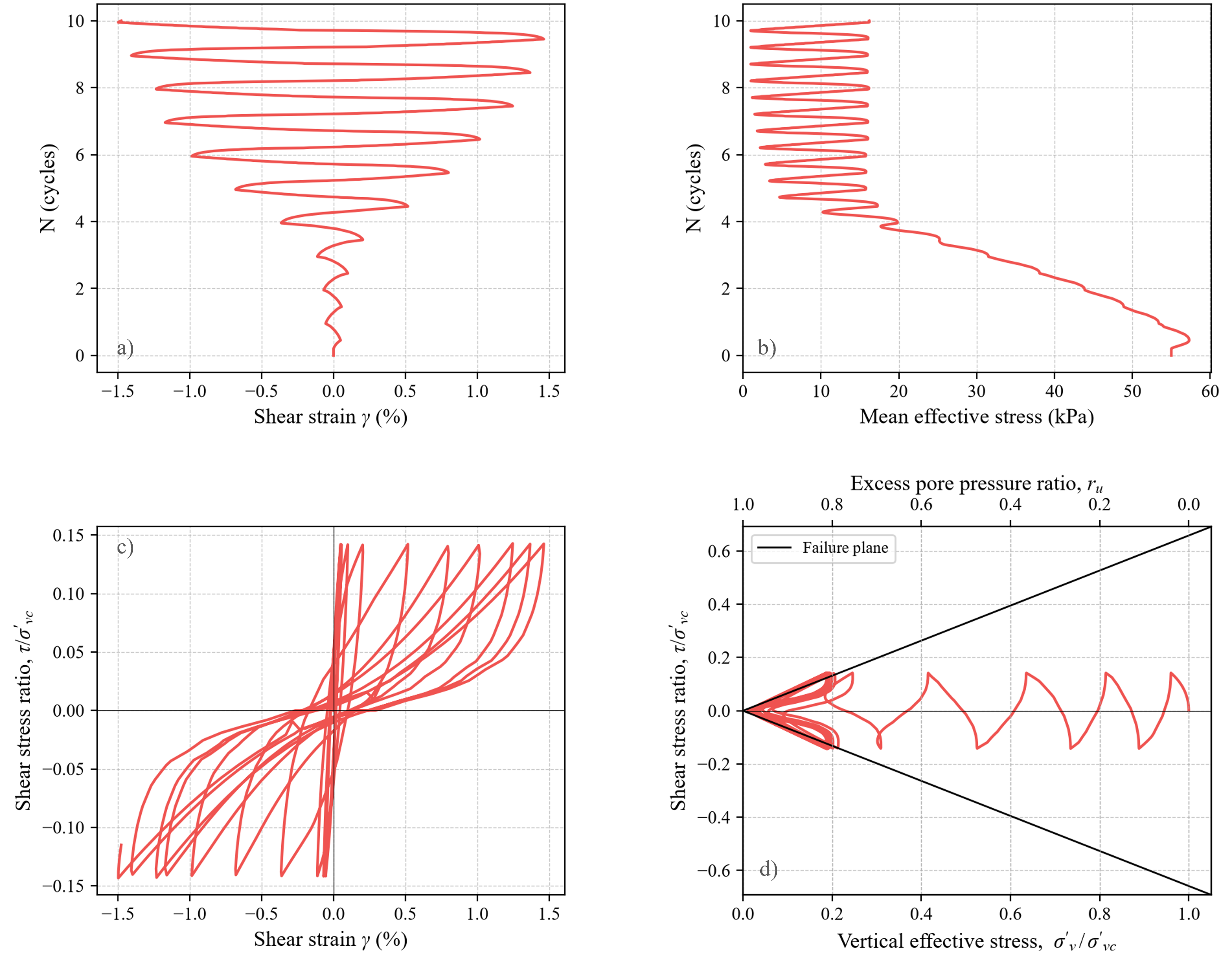
At the element level, the model can reproduce key features of cyclic soil behaviour, including nonlinear hysteretic stress-strain response, cyclic strain accumulation, and excess pore pressure generation. The element-level simulations shown in Figure 2 recreate cyclic direct simple shear tests summarized in Xing (2023) and illustrate how the model captures the soil behaviour over repeated loading cycles. In particular, the response shows shear strain accumulation, hysteresis loops, and movement of the stress path toward lower vertical effective stress as pore pressure builds up. Figure 2b and d demonstrate the model’s ability to simulate liquefaction, as the mean effective stress approaches zero and the excess pore-pressure ratio approaches unity as the number of cycles increases.
These results demonstrate that the new FE-based workflow, with the I-soil model, moves beyond simplified descriptions of soil nonlinearity and simulates key features of soil behaviour under dynamic loading. By embedding advanced constitutive behaviour into an efficient analysis framework, features such as cyclic mobility, excess pore pressure generation, stiffness changes, phase transformation, and strain accumulation can now be evaluated using RSSeismic. This enhanced representation of soil behaviour is a key step toward bridging the gap between practical site response analysis and higher-fidelity numerical simulation, while maintaining the robust and intuitive workflow already familiar to RSSeismic users.
Horizontal Bi-Directional Shaking–Induced Settlement Without Empirical Correction Factors
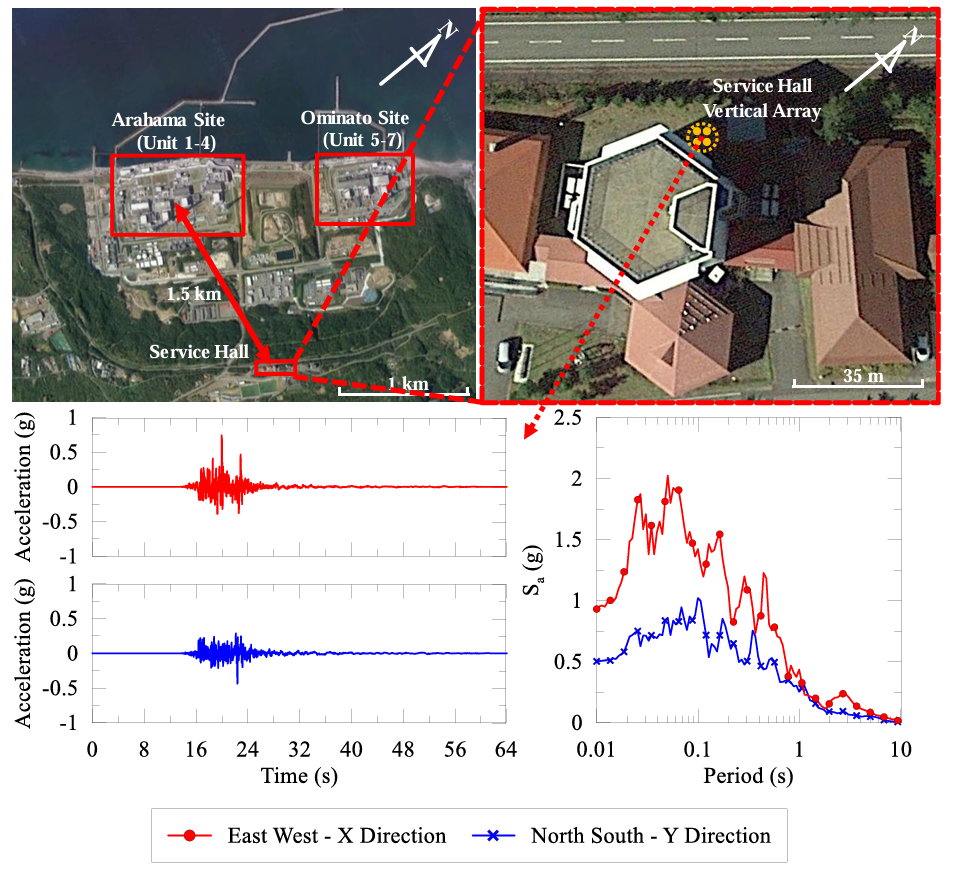
The seismically induced settlement response of dense sands at the Kashiwazaki-Kariwa Nuclear Power Plant during the 2007 Niigata-ken Chuetsu-oki earthquake is used to evaluate the role of horizontal bi-directional shaking. The analyses focus on the Service Hall Array, which is located away from major structures and provides a useful free-field case history for evaluating site response and settlement.
The two horizontal components of motion recorded at a depth of 250 m were applied directly as input motions in the FE-based analysis, allowing the simulation to capture the combined effect of shaking in both directions without the need for an empirical bi-directional factor. Figure 3 shows the acceleration time histories and response spectra for the two horizontal components.
A series of three FE-based analyses using the I-soil model were performed:
- Uni-directional analysis, where the East-West component of the recorded ground motion is applied in the X direction, with zero acceleration in the Y-direction.
- Uni-directional analysis, where the North-South component of the recorded ground motion is applied in the Y direction, with zero acceleration in the X-direction.
- A bi-directional analysis, where the East-West component of the recorded ground motion is applied in the X direction and the North-South in the Y direction.
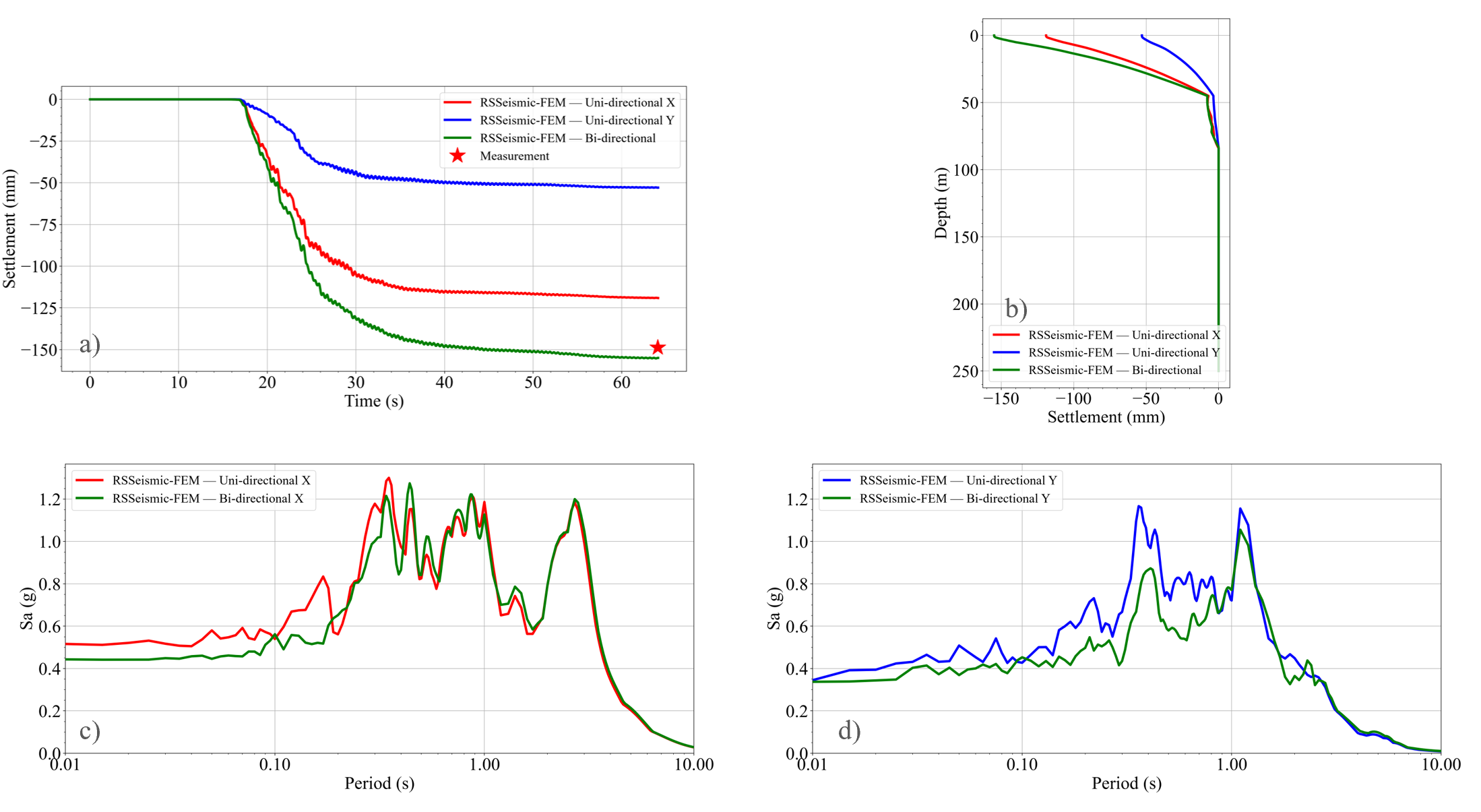
Figure 4 (a & b) shows that uni-directional analysis (X or Y) underestimates the reported surface settlement, while bi-directional analysis provides a close match to the measured surface settlement at the Service Hall Array reported by Sakai et al. (2009).
The effect of bi-directional shaking is also shown in the computed surface response spectra. Figure 4c compares the X-direction response spectra from the uni- and bi-directional analyses, while Figure 4d presents the corresponding comparison in the Y direction. In general, the response spectra from the bi-directional analyses are lower than the corresponding spectra from the uni-directional analyses; likely due to greater nonlinearity. The companion article describes the new bi-directional mode in the ground motion manager designed to streamlined the handling of bi-directional input motions.
Effective Stress Site Response Analysis and Liquefaction
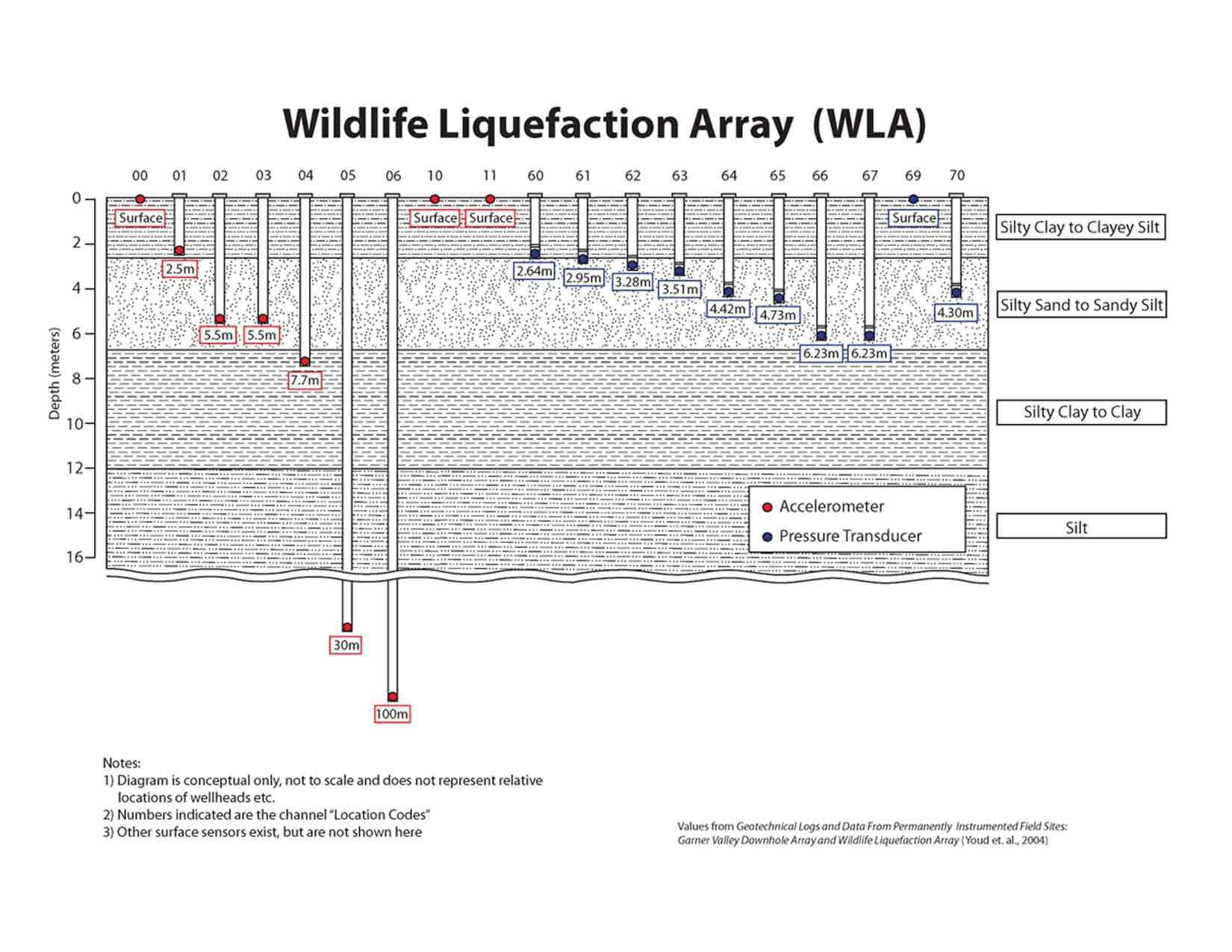
The Wildlife Liquefaction Array is simulated via the new FE-based workflow in RSSeismic v3. The site includes detailed instrumentation, as shown in Figure 5, a well-characterized subsurface profile, ground-motion recordings, and measurements of excess pore-pressure response during earthquake loading.
In this example, the FE-based workflow is used to simulate the dynamic response of the instrumented profile under effective stress conditions by subjecting the soil column to both of the horizontal components recorded during the 1987 Superstition Hills Earthquake.
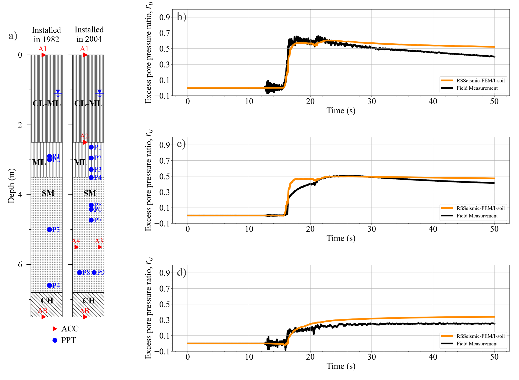
The computed excess pore pressure response is compared to the measured pore pressure records from the Wildlife Liquefaction Array.
Figure 6 shows overall agreement between the simulations and field measurements, demonstrating that the FE engine can capture the buildup of excess pore pressure during cyclic loading and track the progression toward liquefaction in addition to the change in pore water pressure buildup with depth. This agreement is significant because it shows that effective-stress analyses are no longer limited to specialized research platforms or computationally expensive 2D/3D analysis platforms; they can now be performed within a practical 1D site response workflow.
Uncertainty Evaluation with Advanced FE-Based Analyses
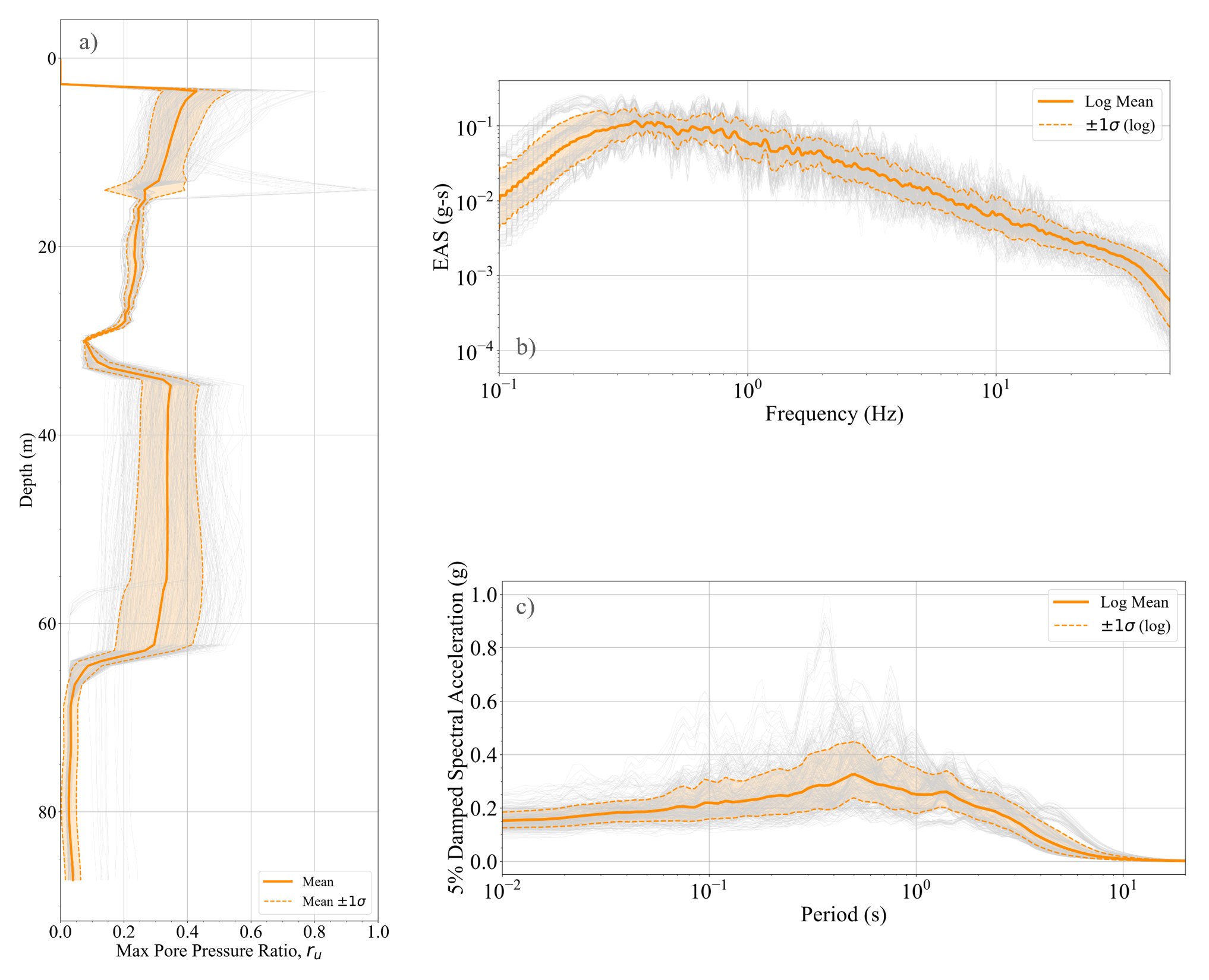
Beyond individual case histories, the new FE-based workflow also makes it practical to evaluate uncertainty in site response using advanced effective stress simulations. To demonstrate this capability, the Treasure Island Downhole Array was used as a test case. Thirty randomized shear-wave velocity profile realizations were generated using the Toro (1995) approach and combined with eleven pairs of input ground motions, resulting in a total of 330 FE-based site response analyses.
Each analysis incorporated the advanced features of the new workflow, including nonlinear soil behaviour, bi-directional input motions, and fully coupled pore pressure generation. The intent of this example is not to provide an exhaustive uncertainty study, but rather to demonstrate that this type of analysis is now computationally feasible within a practical engineering workflow. All 330 simulations were completed in approximately 34 minutes on a laptop with 16 logical processors, highlighting the performance of the new FE engine. This level of efficiency enables engineers to evaluate uncertainty even when using more advanced effective stress formulations.
All simulations were created, executed, and batch processed using the RSSeismic Scripting framework described in the companion article. The resulting simulations were used to evaluate uncertainty using three metrics: the surface Effective Amplitude Spectrum, the geometric mean of the response spectra, and the maximum pore pressure ratio profile. For each metric, the logarithmic mean and plus/minus one standard deviation was computed across the simulation suite. Figure 7 shows the results for this analysis suite.
This example illustrates an important practical benefit of the new formulation. Because the FE engine delivers performance comparable to conventional lumped-mass approaches, advanced simulations no longer need to be limited to a small number of deterministic cases.
Performance of the FE engine
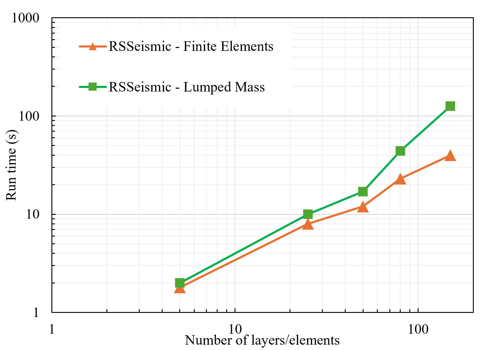
An important consideration for bringing the new FE-based workflow into routine engineering practice is computational performance. Advanced finite element analyses are often assumed to be significantly slower than the conventional 1D simulations, particularly when they incorporate bi-directional input motions, advanced constitutive models, and fully-coupled pore pressure generation. To evaluate the performance of the new engine, a series of benchmark analyses were performed using profiles with increasing numbers of soil layers: 5, 25, 50, and 150 layers. Each case was analyzed using the same general setup: bi-directional input motions, the I-soil constitutive model, pore pressure generation and dissipation enabled, and a 70-second input motion pair.
To compare the new FE-based engine to the conventional lumped-mass approach, complementary nonlinear analyses were also performed using the lumped-mass solver. Since the lumped-mass formulation applies one horizontal component at a time, each component of the input motion was analyzed separately but ran simultaneously. In those simulations, pore pressure generation was represented using the empirical Matasovic (1992) pore pressure generation model. This comparison therefore provides a practical benchmark between the traditional analysis workflow and the new FE-based approach, recognizing that the FE engine is solving a more advanced problem that includes simultaneous bi-directional shaking, 3D soil constitutive behaviour, and coupled pore pressure generation and dissipation.
Figure 8 shows that the FE-based engine scales very efficiently with increasing model size. In fact, the FE solver scales better than the lumped-mass solver as the number of layers/elements increases. For profiles with fewer than approximately 100 layers, the FE-based simulation run times are comparable to those of the nonlinear lumped-mass solver, despite including substantially more advanced physics. This is a key outcome of the development effort: the new workflow does not require engineers to choose between computational practicality and higher-fidelity modelling. Instead, it makes advanced FE-based effective stress site response analysis feasible within the same type of efficient workflow that has made conventional 1D site response analysis widely used in practice.
The same engine that can directly model bi-directional shaking, reproduce pore pressure generation in liquefaction case histories, and support hundreds (and thousands) of uncertainty simulations can do so with runtimes comparable to the current standard for many practical site response problems. As a result, the FE-based workflow provides a unique path for bringing next-generation seismic site response analysis into everyday engineering applications while preserving the speed, robustness, and usability expected by RSSeismic users.
Conclusions
The new FE-based 1D site response workflow expands the capabilities of conventional site response analysis while maintaining the efficiency and usability required for routine engineering practice. Its direct use of paired horizontal ground motions provides a natural connection to ground motion models based on the orientation-independent Effective Amplitude Spectrum (EAS), while its representation of phase transformation and shear-induced volumetric response supports the evolving expectations for nonlinear site response modelling being considered in the upcoming 2026 NEHRP Recommended Seismic Provisions. The examples presented demonstrate the ability to:
- Perform bi-directional site response analyses through the direct application of two horizontal earthquake motion components within a single simulation.
- Represent advanced soil behaviour including nonlinear hysteretic response, cyclic strain accumulation, stiffness degradation, and shear-induced volumetric response.
- Conduct effective stress site response analyses with fully coupled pore pressure generation and dissipation, including simulation of pore pressure buildup through liquefaction.
- Evaluate seismic settlement directly from the computed stress-strain and pore pressure response without relying on empirical bi-directional correction factors.
- Perform uncertainty evaluations within a practical engineering workflow.
- Deliver computational performance comparable to conventional lumped-mass-based site response analyses for many practical problems, enabling advanced nonlinear and effective-stress simulations on standard engineering hardware.
- Maintain a streamlined RSSeismic workflow that allows engineers to transition from conventional site response analysis to advanced FE-based simulations without significant changes in model development procedures. This new capability enables a more consistent calibration pathway to 2D and 3D seismic soil–structure interaction analyses through the use of advanced constitutive models and finite element formulations.
References
Ancheta, T. D., Darragh, R. B., Stewart, J. P., Seyhan, E., Silva, W. J., Chiou, B. S., ... & Donahue, J. L. (2013). Pacific earthquake engineering research center. PEER strong motion database (University of California, Berkeley, 2005).
Bayudanto, A. P. (2019). Numerical simulations of site response and seismic settlements at Kashiwazaki-Kariwa Nuclear Power Plant, Japan (Doctoral dissertation, University of Illinois at Urbana-Champaign).
Groholski, D. R., Hashash, Y. M., Kim, B., Musgrove, M., Harmon, J., & Stewart, J. P. (2016). Simplified model for small-strain nonlinearity and strength in 1D seismic site response analysis. Journal of Geotechnical and Geoenvironmental Engineering, 142(9), 04016042.
Matasovic, N., & Vucetic, M. (1992). A pore pressure model for cyclic straining of clay. Soils and Foundations, 32(3), 156-173.
NEHRP Recommended Seismic Provisions for New Buildings and Other Structures. National Institute of Building Sciences, Washington DC, final publication pending, September 2026.
Numanoglu, O. A., Hashash, Y. M., Olson, S. M., Cerna-Diaz, A., Rutherford, C. J., Bhaumik, L., D., Centella, & Weaver, T. (2023). A simplified three-dimensional constitutive model for seismic modelling of dense sands. Soil Dynamics and Earthquake Engineering, 167, 107794.
Sakai, T., Suehiro, T., Tani, T., & Sato, H. (2009). Geotechnical performance of the Kashiwazaki-Kariwa Nuclear Power Station caused by the 2007 Niigataken Chuetsu-oki earthquake. Case History Volume for Performance-Based Design in Earthquake Geotechnical Engineering, Technical Committee, 4, 1-29.
Tokimatsu, K. (2008). Geotechnical problems in the 2007 Niigata-ken Chuetsu-oki earthquake. In Geotechnical Earthquake Engineering and Soil Dynamics IV (pp. 1-30).
Tokimatsu, K., & Seed, H. B. (1987). Evaluation of settlements in sands due to earthquake shaking. Journal of geotechnical engineering, 113(8), 861-878.
Toro, GR (1995). Probabilistic models of the site velocity profiles for generic and site–specific ground–motion amplification studies. Appendix in Technical Rep. No. 779574, Brookhaven National Laboratory, Upton, NY. http://pacificengineering.org/bnl/Bnl_rpt.zip. Accessed 15 Mar 2022.
Xing, G. (2023). Seismic site response analysis with porewater pressure generation (Doctoral dissertation, University of Illinois at Urbana-Champaign).
Yee, E., & Stewart, J. P. Settlement from Seismic Compression at a Vertical Array near a Nuclear Power Plant. In Geotechnical and Structural Engineering Congress 2016 (pp. 1638-1645).
Bring advanced FEA into your site response workflow
Seamlessly integrate orientation-independent Effective Amplitude Spectra (EAS) and phase transformation behaviour into your analyses using RSSeismic.
Start Your Free Trial